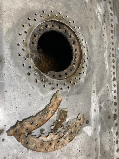
The P-39 restoration project is still very much a work-in-progress. The latest addition to the project is the Fuel Tank Covers and Filler Cap. When the existing components were removed there were visible signs of corrosion so it was decided to replace the inner mounting rings as well as the covers/caps.
Each cap assembly consists of an inner mounting ring, a Goodyear-type sealing ring, and cover plates. It is important to consider the varying thicknesses of the sheet metal at each location, as this can lead to slight differences in the profiles of the mounting rings. Typically, when we develop these types of parts, we mark the holes in situ based on existing hole patterns to ensure a proper fit. This is usually done because the holes are evenly spaced between two known locations, which can vary during manufacturing. However, for these covers and caps, we have precise knowledge of the hole locations, allowing us to ensure an accurate match.
The flush rivets used throughout are the 35R1 Bell standard, featuring a 120-degree countersink designed for thin sheet materials. An equivalent Boeing standard for this type of rivet is also available. In the assembly drawings, I have spaced the components apart to enhance clarity. I should note that the drawings shown are still a work in progress.
Update: Ready for issue:
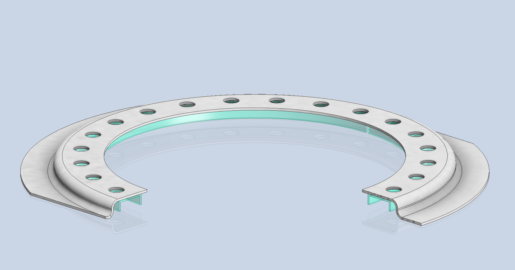
This is the final assembly, typical for the fuel tank covers and caps.
The lower ring features an Elastic Stop Nut Gang Channel. It is presumed that this channel was designed according to Bell standards when it was constructed. I have examined various companies that supply similar Gang Channels; however, the hole centers in their standard components differ slightly from our specifications. I suspect that we will need to have a bespoke fabricated item to meet our requirements.
It may be possible to purchase Elastic Stop Nuts and retaining springs from companies like Howmet Aerospace and create a channel to match the design in the second image below. I will provide an update later on how we will proceed.
I will also soon be able to provide you with more information about the P-39 restoration and a gallery of images showcasing the latest work.
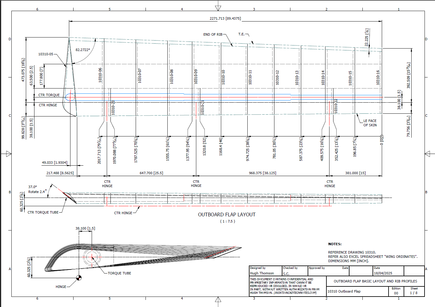
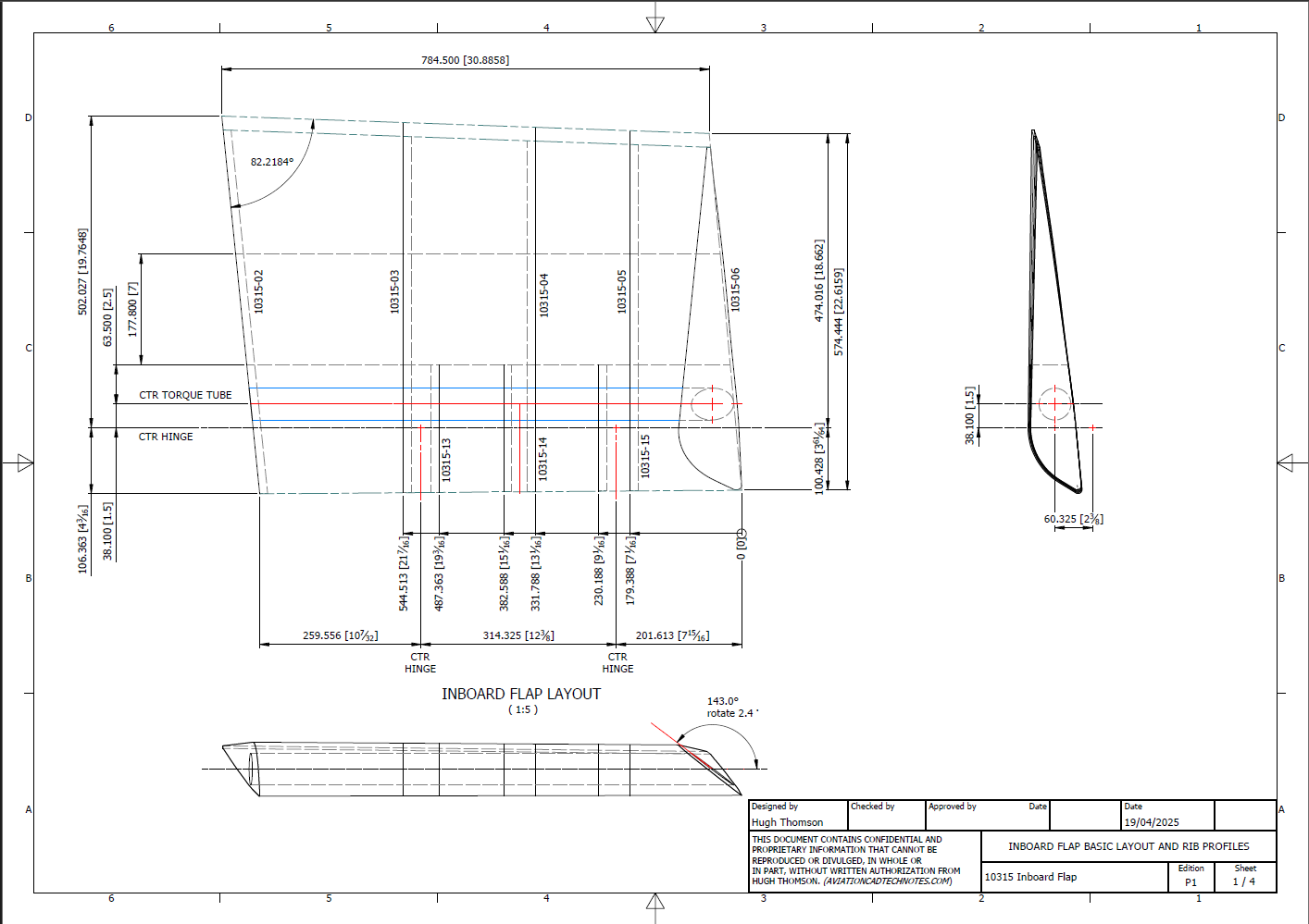
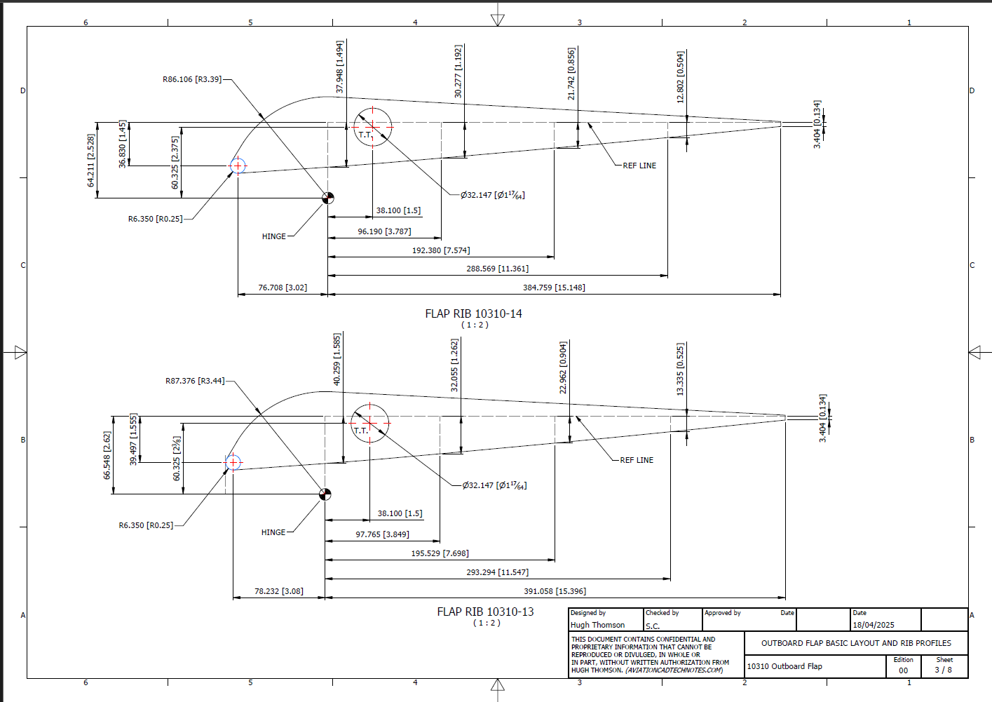
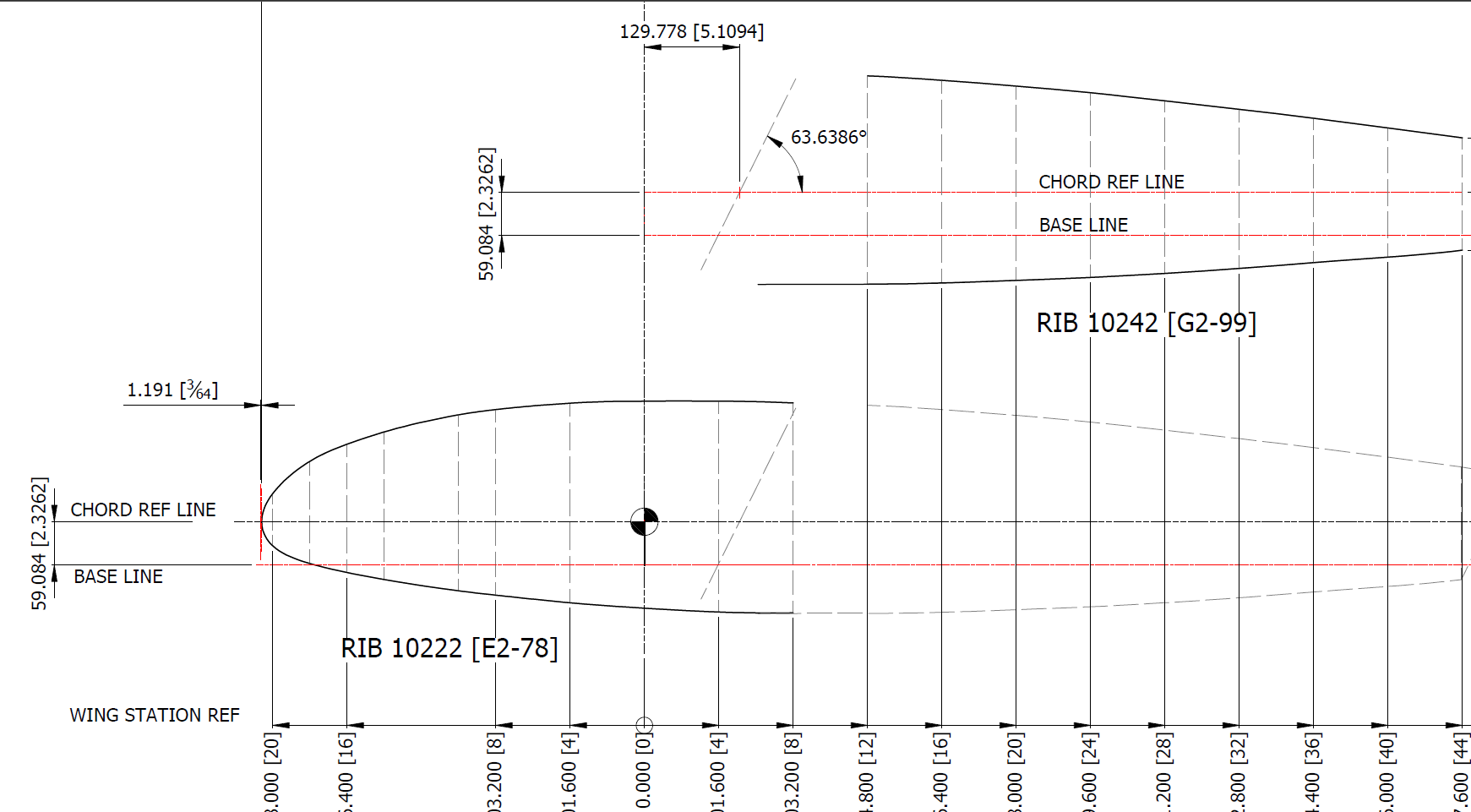
I have added new updates to the FM2 CAD/Ordinate dataset, completing assemblies for the Aileron, Outboard Flap, and Inboard Flap. In addition to the 3D CAD models, we have the fully dimensioned 2D drawings defining the profiles for all ribs.
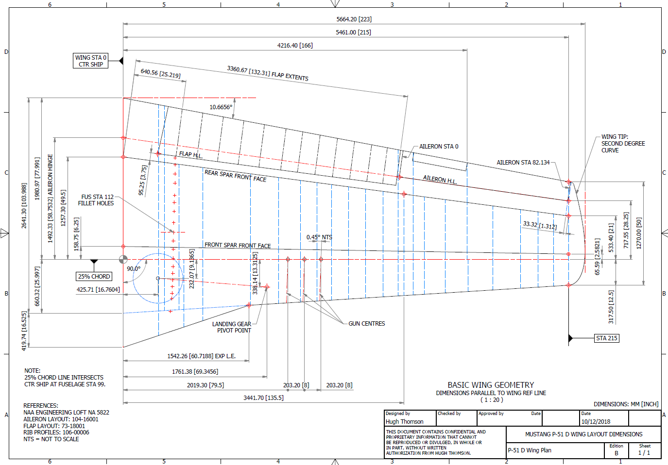
Wing Layout and Rib Profiles:
The wing ribs comprise 3 separate rib profiles for the Leading edge, Mid-section, and Trailing edge. The detailed drawings show the complete profile and the individual component profiles separately. This will identify the blueprint drawing number in each case and the related blueprint scan file name.
Every drawing will be available as a full size Autocad DWG. All rib profile offsets are listed in a comprehensive Excel spreadsheet.
The CAD/Ordinate datasets are designed to offer detailed documentation of the dimensional information pertaining to the core profiles of various aircraft components. This includes elements such as fuselage bulkheads, cowls, vertical stabilizers, horizontal stabilizers, wings, rudders, flaps, ailerons, and elevators. Essentially, these datasets provide all the dimensional information needed to develop the main profiles for aircraft construction.
The research studies were conducted to fill in important gaps in information and to clarify unclear details. Often, data on blueprints can be difficult to read, making it necessary to record and analyze the bulkhead or rib profiles in CAD. This process helps accurately determine the correct dimensions.
The examples of ordinate dimensions above are not necessarily the worst; in fact, there are truly poor examples that exist. To tackle these issues, we should start by recording the known dimensions in Excel and making educated guesses about the worst examples. Next, we can create each profile in CAD. This CAD profile will give us a clear visual representation of any anomalies in the curvature, which can be further analyzed through curvature analysis to identify low and high spots. This process is done for every rib and bulkhead profile where we have ordinate dimensions.
The spreadsheets above are typical examples of CAD/Ordinate datasets. The first spreadsheet contains the Ordinate record for the P-38, while the second one features the Aileron sheet for the FM2. You may notice a Linear Regression analysis table included in the FM2 sheet. Initially, determining the individual profiles of the ribs or bulkheads is just the first step; we now need to assess the assembly of all these components and check for proper alignment.
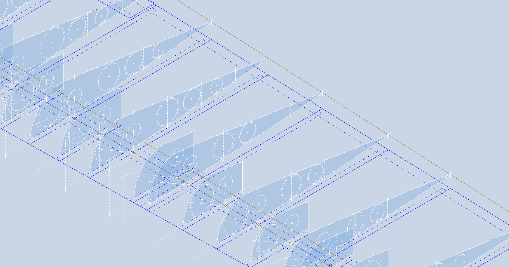
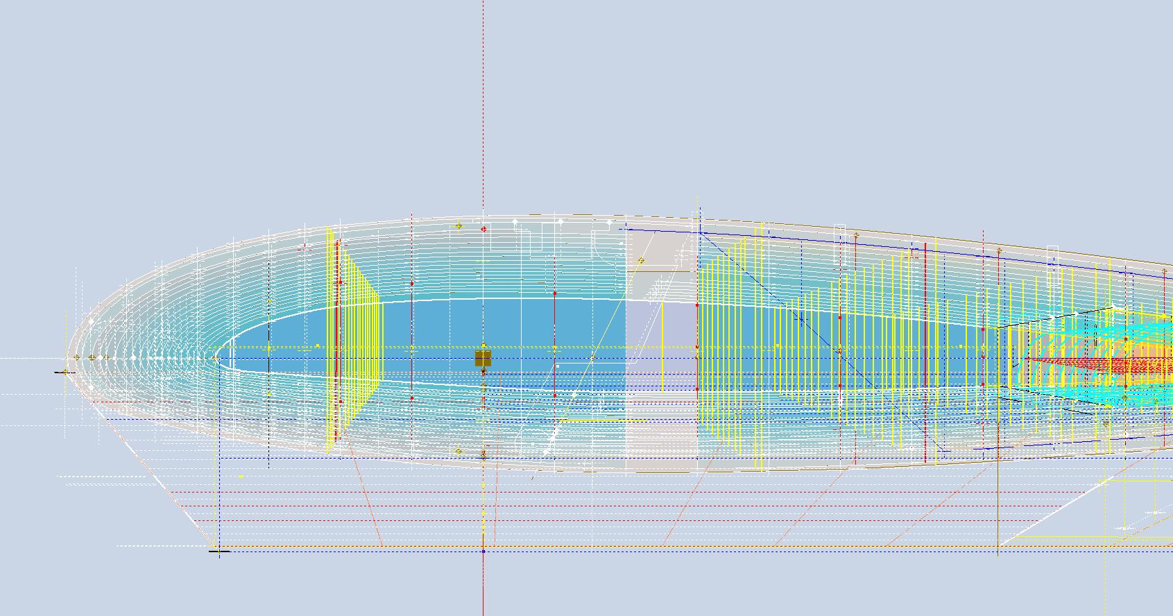
Each drawn sketch profile in CAD will serve as the border for containing a surface patch.
There are two primary reasons for doing this. First, it provides us with a plane that can be converted into a working surface, which can be utilized in any CAD product. Secondly, it provides us with a tangible element that we use to check assembly cross sections at key locations for alignment checks.
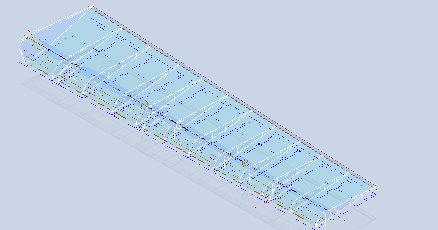
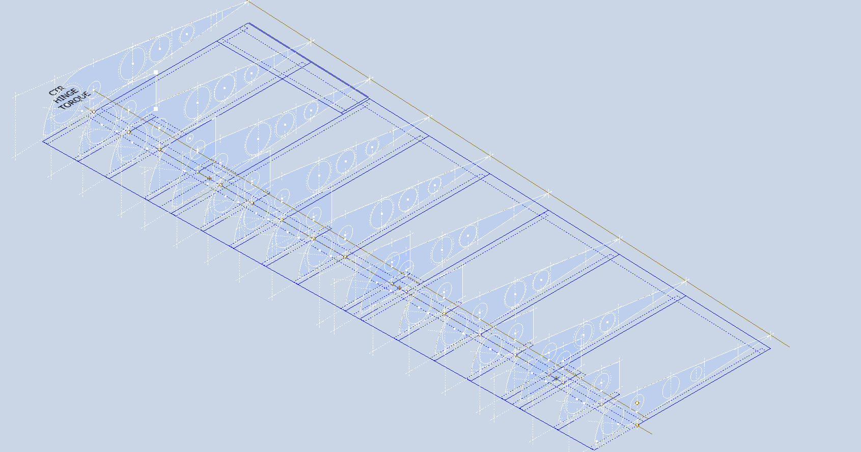
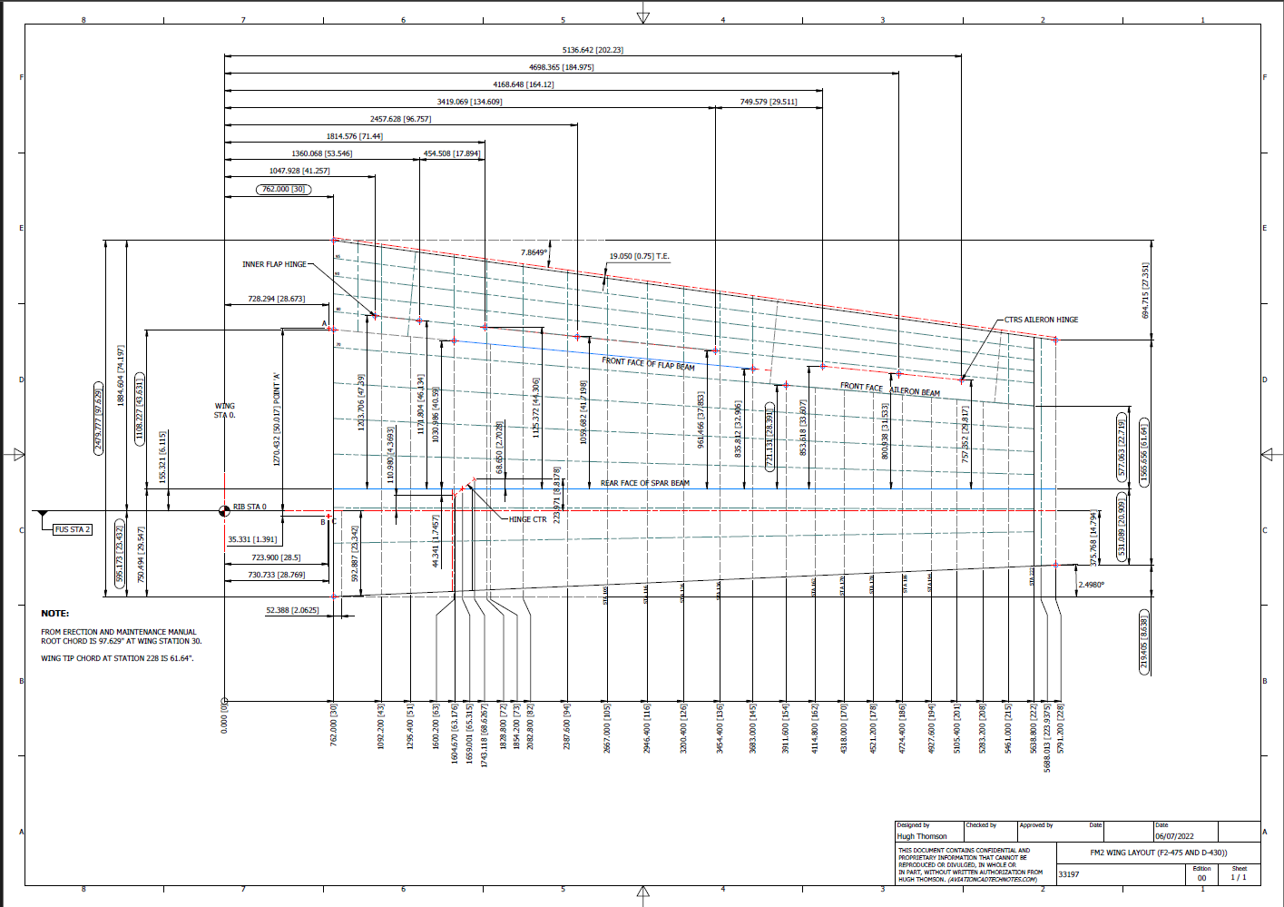
For example, consider the wing of the FM2. The wing assembly has been converted into a part file, and cross-section sketches were created at various chord locations: 30%, 60%, 70%, and 80%. Each sketch utilized the “Project Cut Edges” function to generate a cross-section of each rib. As shown in the second image, the array of lines representing the rib cross-sections provides a visual aid to identify high and low spots on the wing assembly. By creating a surface plane for each rib, we were able to generate these cross sections effectively. There were a few high and low points, which were double-checked and rectified.
If we require additional verification and strive for precision, we could use Excel’s Linear Regression to generate the coordinates for a Best Fit Line and make adjustments as needed. However, this approach may be excessive since our primary goal is to clarify the original blueprint data and apply it to identify appropriate rib and bulkhead profiles within acceptable parameters.
We can also use Linear Regression to give us an overview of how the ordinate profiles align with one another and to identify any discrepancies. Typically, acceptable parameters are within +/- 0.01 inches (or 0.254 mm), as specified by the dimensions on the blueprints, which usually only provide accuracy to two decimal places. Sometimes, as was the case with the P-51 and P-38, we had key design parameters that allowed us to calculate the exact profiles for each wing.
Validating dimensional data is crucial because the actual wing construction may not always match the accepted specifications. The design specifications for the FM2 call for a NACA 23015 airfoil at the root and a NACA 23009 airfoil at the tip. You might be surprised to learn that the NACA 23009 is a modified version of the standard 23009. Nothing is therefore assumed or taken for granted.
The CAD/Ordinate datasets are the result of extensive and thorough research and analysis, often taking many months of work, sometimes around the clock. These spreadsheets include every known ordinate dimension for various aircraft, gathered not only from blueprints but also from manuals, reports, and even correspondence. The CAD/Ordinate packages also include various 3D CAD models in various formats, including 3D DWG and fully dimensioned 2D DWG. All documents provided are fully editable so you can adapt the information to your work processes.
For more details on using the Ordinate spreadsheet data for your own CAD systems, see my earlier post here: Ordinate Overview
With over 45 years of experience in structural and mechanical engineering, my expertise influences everything I do.
In summary, the purpose of the CAD/ordinate datasets is the result of intensive work and research to provide the user with correct usable data that can be utilized in any CAD system.
When you buy CAD/Ordinate datasets and Blueprint collections from me, you support my ongoing research to provide the most comprehensive and probably the most accurate dimensional information about various aircraft. This blog and my research work would not be possible without your support.
The Grumman Goose project is both challenging and frustrating; it is definitely not a straightforward aircraft to work on. I have primarily focused on updating the empennage, which includes the vertical stabilizer, horizontal stabilizer, rudder, and elevator. During the development of the ordinate study, I observed discrepancies in the documented locations of various components. Let me explain what I mean.
Upon reviewing the CAD drawings on the left and comparing them with the Maintenance Manual diagram, I noticed that the level of the ribs varies by 1/16 of an inch. This discrepancy caused me immediate concern, and I began to wonder where I might have misinterpreted the Grumman drawing data. Therefore, I felt it was necessary to review and verify the information.
Initially, we do not have any reference location information on the Rudder Layout drawing. Normally, you would expect reference dimensions to the fuselage centerline or a fuselage station reference, but there are none. We do, though, have locations of the Hinges on other drawings for the Station bulkheads and Fin layout which in turn will help derive location information for the Rudder.
The first image above is the bulkhead layout at Station 36, which specifies the centre of the hinges 1, 2, 3, and 4 relative to the Fuselage Ref Line.. The second image is the bulkhead at Station 33, which shows the dimension of 65 13/16″ to the top of the Lower Rib on the Vertical stabilizer Fin.
I am looking to verify the dimensions and locations of the rudder ribs and hinges in relation to the Fuselage Reference Line. To accomplish this, we will start with the information we have and determine what additional information we need. The first image confirms that the CAD drawings for the rudder accurately depict the positions of the hinges. The second drawing further supports this; the “Top of Rib” location refers to the lower rib of the fin which includes the locations of the hinge centers. At this point, we have established the correct locations of the rudder hinges from two different sources.
Having determined the hinge locations, we know that the ribs for the rudder are offset by 5/8″ on either side of those locations, which allows us to derive the final levels noted on the Rudder Layout CAD drawing. Does this mean that the Grumman drawings, and therefore the CAD drawings, are correct while the manuals are incorrect? Yes and No…let me explain…
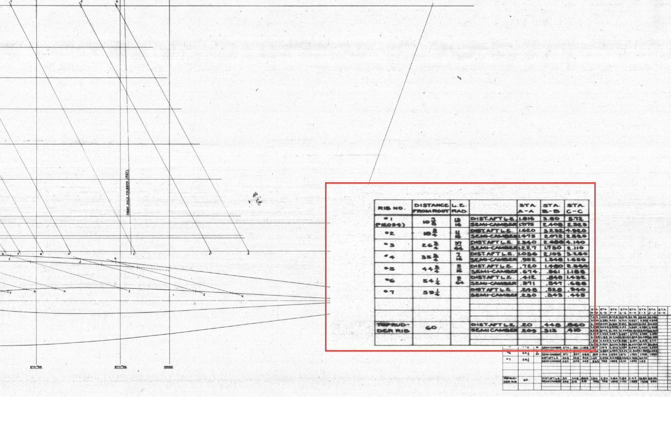
The first image is the Lines Diagram for the Vertical Stabilizer Fin Ribs. In the Table of Offsets, you will notice a list of dimensions from the “Root,” with the first rib specified at 10 7/8 inches. If we overlay these dimensions onto the CAD drawing, we observe a 1/16-inch discrepancy to the top of the first rib. However, all other sources, including those mentioned above and additional references not listed, such as the fuselage Lines layout, indicate that the top of the rib is correctly positioned in the CAD model (second image), contradicting the information provided in this Table of Offsets.
So what is going on?
We should take into account the revision history of the Grumman Goose development. If you examine their drawings, you’ll notice that they have made numerous revisions, some of which are labeled with letters as late in the alphabet as “R.” That indicates a significant number of changes.
I believe that various details have changed over the year, with the more prominent aspects being updated while the less prominent drawings remain unchanged. Regarding the manuals, it seems they were created early in the project, and it may have been considered too labor-intensive to update the level references. This aircraft is quite complex, and I can only imagine the effort involved in both its development and the ongoing updates to its design.
Whenever a small anomaly becomes apparent, I will make an effort to gather information from other drawings to verify the final result. This is one reason why these Odinate studies take so much time; it is crucial to ensure that the final study represents the most accurate dataset possible. If I were building a Grumman Goose replica, I would be using my datasets.
Progress Update 18th March:
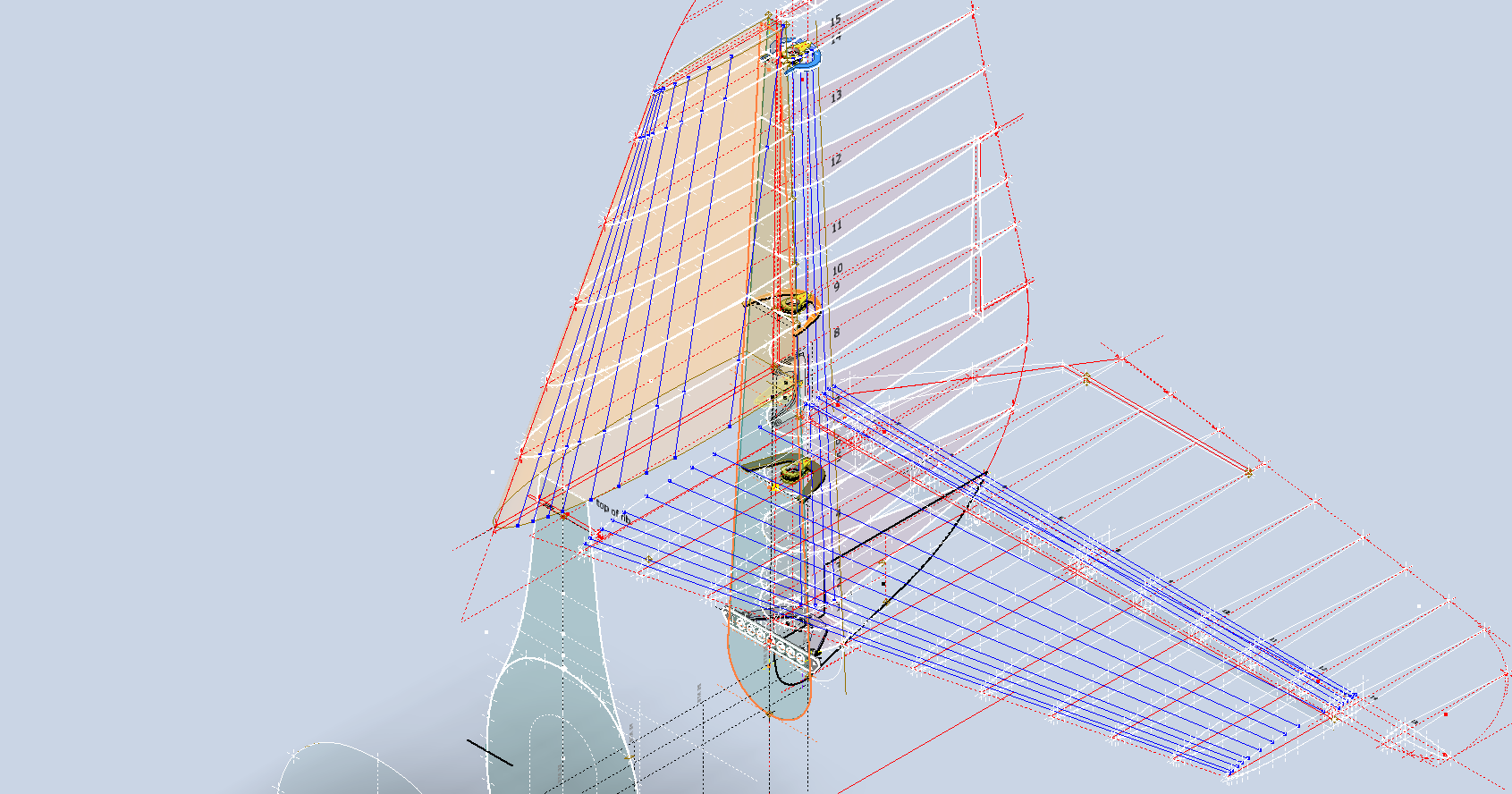
A few screen shots showing the latest updates to the JRF Goose. The wing has been completely rebuilt with all dimensions verified.
On the CAD/Blueprint resource page, I have compiled a list of Ordinate Dimensional studies for various aircraft. The purpose of these studies is to gather all known dimensional information in a format that can be easily transferred to any CAD system. Additionally, they serve as a dimensional check to verify the designer’s intent and assess the accuracy of data from different resources, including blueprints, manuals, and correspondence.
Let me give you an example:
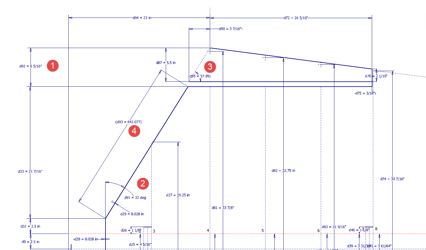
I am currently updating the CAD/ordinate dataset for the Grumman Goose and have already identified a few anomalies in the empennage. This document includes the layout study for the elevator, and you will notice that, based on the blueprint dimensions, the trim tab is incorrectly positioned.
At first glance, it may seem that the dimension labeled “1” is incorrect, as it appears to be the catalyst that causes the trim tab to go out of alignment. However, when we consider the length of the diagonal line labeled “4,” which measures 642.07 mm (25.27 inches), we find a discrepancy with the blueprint that specifies this dimension as 25 inches. Additionally, this measurement does not align with the chord dimension for the rib labeled “2.” As it stands, the angle of the sloping line appears to match at 32 degrees for both the trim tab and the elevator.
This type of issue frequently arises when working from blueprints for any aircraft project. To address it, further research is required, which will involve cross-referencing all part and sub-assembly blueprints in the affected area, reviewing general arrangement layouts, and consulting relevant manuals. It is essential to understand the design intent in order to develop the most likely solution. I have even extracted key information from correspondence that was important for the P-51 Mustang.
Small dimensional discrepancies are common in these projects, not only due to converting inch dimensions to millimeters but also because of typographical errors on the blueprints themselves.
The screenshots of the Ordinate spreadsheets display the dimensional information for the Horizontal Stabilizer and the Rudder. Several dimensions are highlighted in red, indicating errors on the blueprints that have been corrected. The dimensions marked in gray represent the measured dimensions from the CAD model. This discrepancy arises from the inherent accuracy of the specified dimensions, which may only be precise to 1/32″. As a result, minor deviations can occur during the CAD development process. Understanding these differences requires careful consideration of all key layout dimensions and material thicknesses, as they all influence the final derived dimensions. Nothing is taken for granted.
The CAD/Ordinate datasets compile all known dimensional information from various thoroughly researched sources, providing a comprehensive collection of data. This data is presented in editable spreadsheets, fully dimensioned drawings, and 2D/3D CAD drawings and models.
Elevator Layout Solution:
I have identified a solution regarding the layout dimensions. The dimension labeled as “1” is incorrect, but it is not the primary issue. Firstly, the Trim Tab has its own drawing #12530, which indicates that the overall length of the tab is 28.75″. This measurement is incorrect; it should be 29.75″. Additionally, other dimensions are also contributing factors.
In the bottom left corner, we find the specifications for the Hinge and Torque Tube, where two dimensions are marked with a tilde underscore to indicate that they are approximate. Generally, approximate dimensions are expected to be close to the actual measurements; however, that is not the case here. By adjusting the overall length of the Trim Tab along with modifying the approximate dimensions at the hinge torque, and also ensuring proper alignment with the known trailing edge, I have arrived at a workable and accurate solution.
Tech Tip: Using the Ordinate Spreadsheets:
I often get asked this and I have written about using the Ordinate spreadsheets before. Bumping it up to a more recent post, this one; I thought I would share a quick tip.
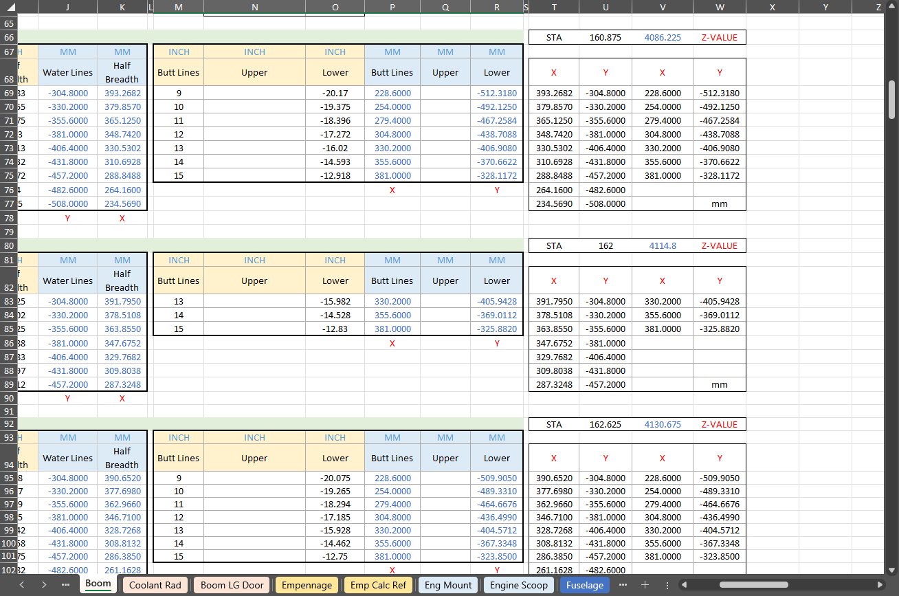
The Ordinate data spreadsheet is on the left, while the other is an empty spreadsheet that I use to paste data for a specific frame or rib that the CAD system can access. The empty spreadsheet just sits on my desktop, which makes it accessible.
Generally, the format of the data table is set out according to the original resource, which makes it easier to cross reference and check. This is not entirely ideal for CAD access as the X, Y coordinates are in rows and not in columns. The fix for that is easy, copy the data from the spreadsheet as required, select Paste Special in the destination spreadsheet making sure to select the “Values and Formats” and the “Transpose” options. The former ensures the data format remains the same and the purpose of the Transpose function is to convert data rows to columns. This gives us the data in X, Y columns ready for insert into the CAD system.
Note the “inch” header…I am using a millimetre template in my CAD system so I have to specify the unit of measure when I select from the first table. By the way, there is a second table that has all those values converted to millimeter anyway, so we could easily use that…in this case, you would not require a header row.
In other datasets, I have developed additional data tables in the spreadsheet, where I have transposed columns for the X, Y, and Z coordinates, such as those for the P-39.
I receive a lot of feedback from users about the spreadsheets, specifically regarding the time they save on projects since they do not have to manually input data themselves.
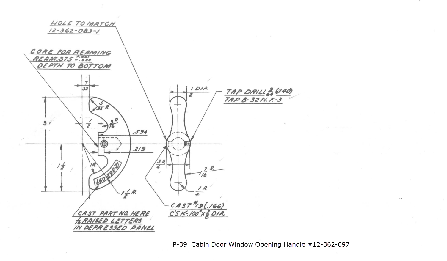
This little part at first glance seems fairly straightforward, but there are a few caveats.
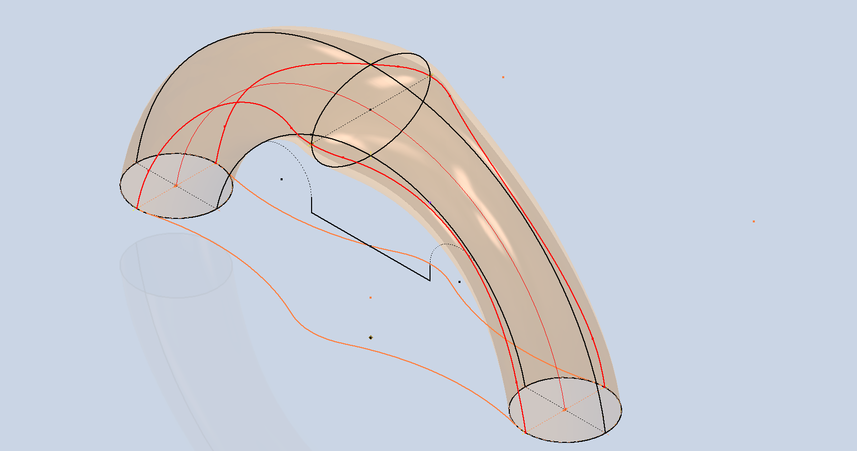
It has been a while since I specifically wrote a CAD solution Technote, and this seemed to be an ideal subject for surface modeling and 3D sketching. The dimensions define the outline for the front view, which is fine, and the plan view, which details a thinning of the handle cross section.
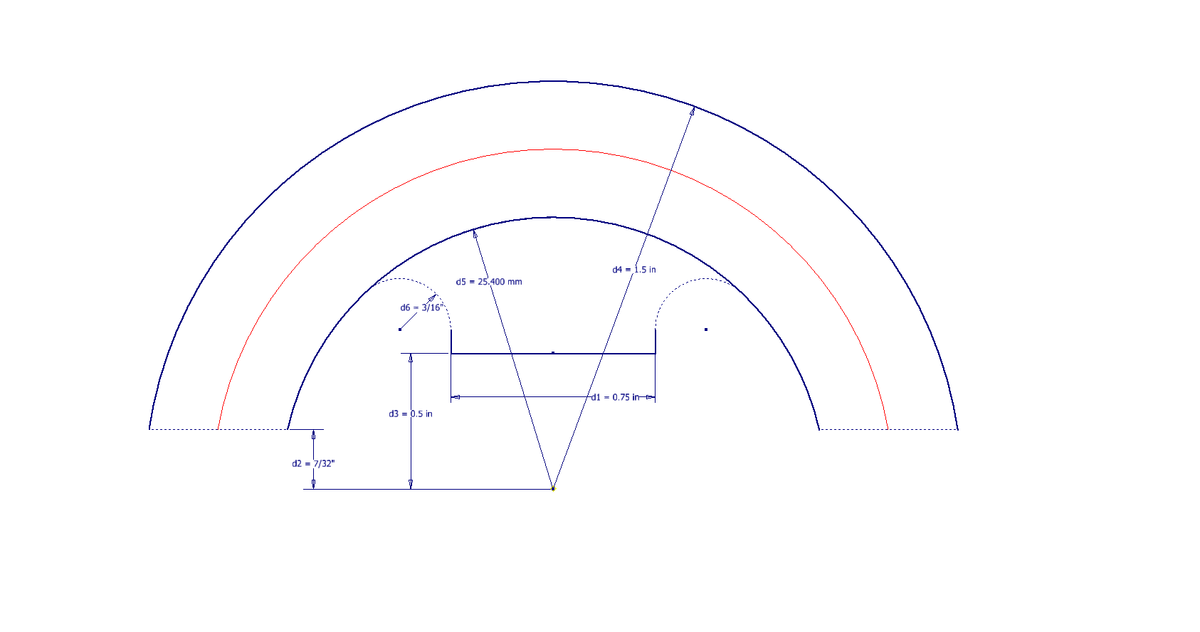
The thinning of the handle occurs in a specific plane as indicated in the plan view, while the front view maintains a consistent full depth diameter. Before diving into the modeling process, it’s important to pause and consider how to approach this design. Typically, my first step involves sketching out what is already known, which helps clarify the information we still need to gather. This initial sketching phase is crucial for laying the groundwork for an effective modeling strategy.
In each case, you’ll notice that these profiles are not closed. The base lines shown in the front view are defined as construction lines, and the end curves in the plan view are also intentional. This design choice allows the main profile lines to be used later for creating a Loft and for selecting a 3D Sketch Intersection. The center line of the arc in the front view will serve as the second selection for this 3D sketch. Additionally, note that the curves in the plan view are elliptical.
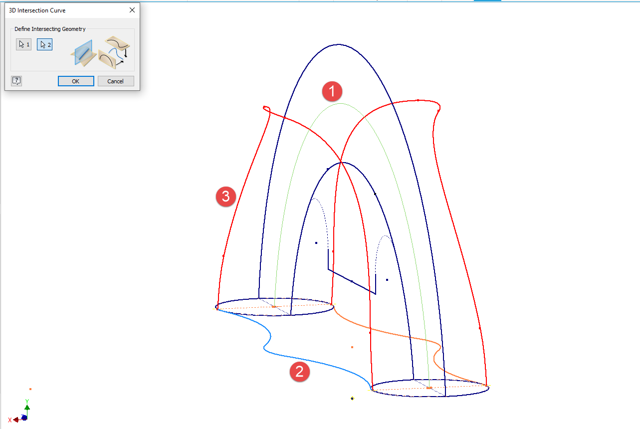
The purpose of the 3D Intersection sketch is to define guidelines for the eventual loft. Using the 3D sketch feature, we first select the center line from the front view and one curved edge from the plan view sketch. The resulting intersection will serve as the 3D path for the loft. This process needs to be repeated for both sides of the handle. The ellipses that will form the ends of the loft are created in a separate sketch from the previously mentioned plan view. This keeps them as distinct entities.
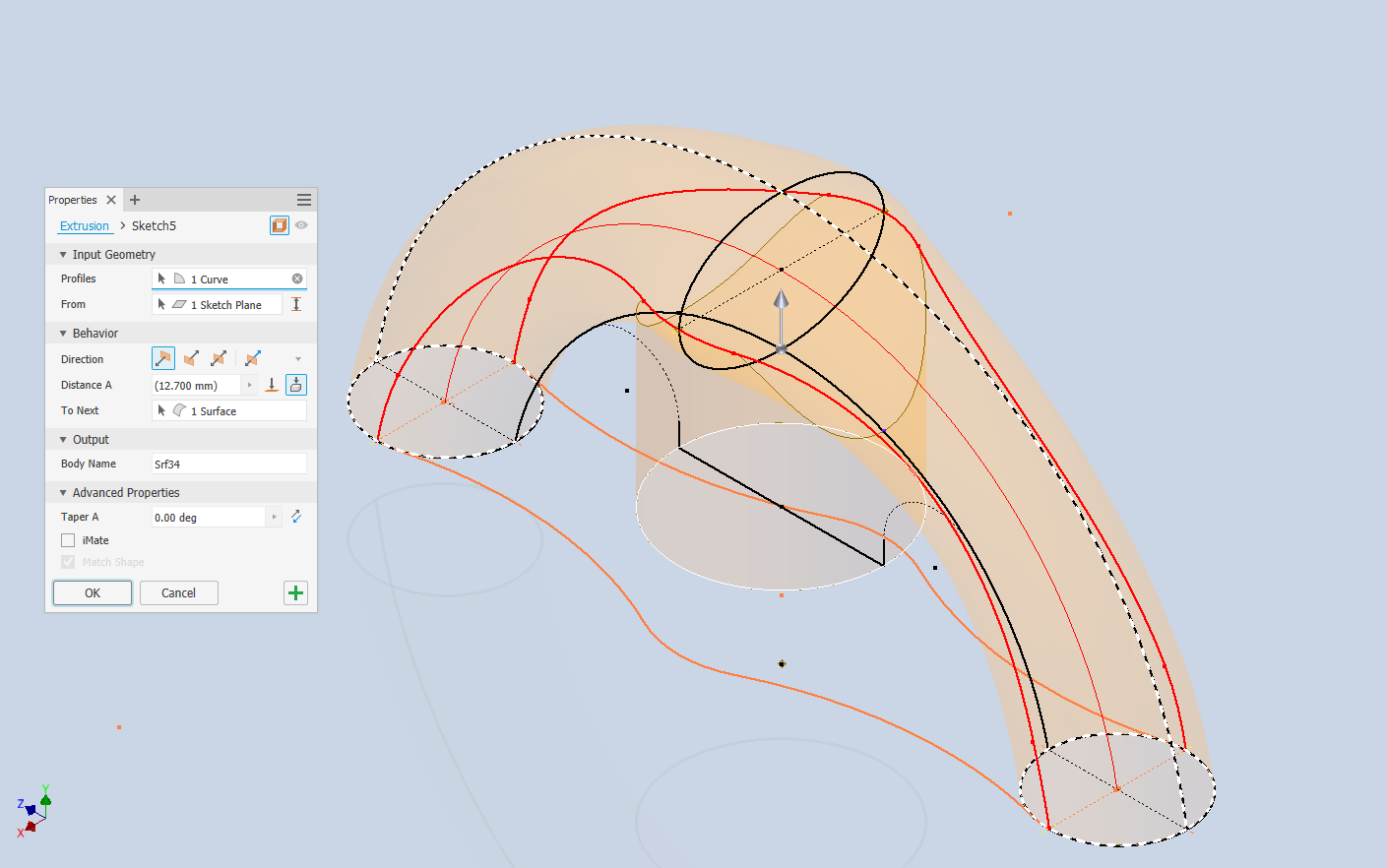
Hold on a moment; where did the ellipse in the middle of the arch come from? If we simply loft the two end profiles of the arch, as shown earlier, we can create an acceptable model, but it won’t be ideal. In the second image, where both surfaces are overlaid, you can see that this approach tends to create a diamond-like cross-section in the center. While this is not entirely incorrect, incorporating the ellipse in the center of the arch results in a much better finished surface, ensuring good continuity, as demonstrated.
Once we have the arch lofted surface, we extrude the centre section circle to match the surface contours.
We then use this extrusion to trim the underside of the arch surface, apply patch surfaces to fill in the ends of the arch and this centre section. Then stitch everything together and we have the main solid model.
Apply a fillet as shown to the underside; note the fillet in this case is better selected as a tangent fillet and not a G2 curvature. It is often tempting to overuse the G2 fillet option as the perceived notion is that it creates a smoother finish, which by the way is correct, though in a case like this it tends to sharpen the fillet corners which is not good. Something to watch out for when applying fillets.
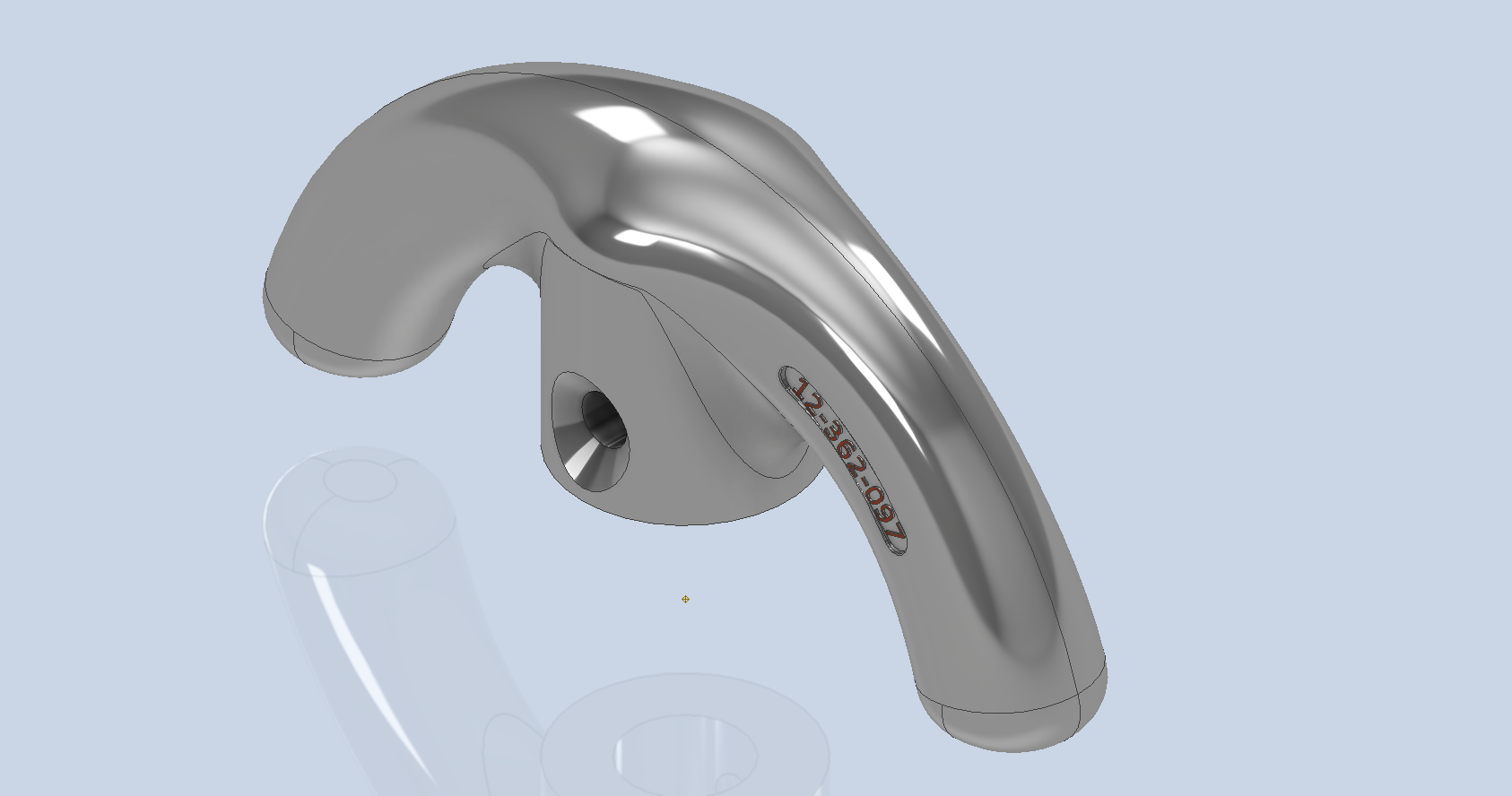
To finish up we add the holes as specified, fillet the ends of the arch (a good opportunity for a G2 fillet) and add the part identifier. The final part should look something like this:
In summary, when developing surface models, it’s beneficial to explore your options and start by creating sketches that support your plan of action. Consider using 3D intersections to define loft paths, and incorporate additional geometry as needed to maintain the circularity and continuity of the final surface.
This part is ready for manufacturing, which will probably be 3D printed for this static display restoration.
Typical Design Workflow:
Usually I would initially receive an inquiry via email from companies like Planes of Fame for a 3D CAD model of a specific part or assembly. Typically, the request includes a brief description of what is needed and not necessarily the actual part number. In this instance, it was for “the handle for operating the window glass.” I then searched through my archives to locate this item, reviewed the part’s blueprint, and checked which parts or assemblies it connects to ensure I have all the relevant information.
I will make every effort to start working on the CAD model as soon as possible, regardless of the time of day, to minimize any delays. For example, I received an inquiry about a part at 9:17 PM last night for the “P-39 Throttle Control Mount.” Following the established procedure, I was able to begin working on it relatively quickly on a Friday evening. The finished part (#12-631-027) was completed and submitted on Saturday at 11:17 AM. The final design included both the original 3D CAD model and a fully dimensioned 2D drawing, which is essential for verifying that all dimensions conform to the original blueprint.
This part will likely be 3D printed for the restoration of the static display, so the 2D drawing serves both as a dimensional check and a reference for manufacturing. If the inquiry had required a metal casting manufacturing process, the drawing would include more detailed information about part machining and the tolerances necessary for a full-metal manufactured item.
If you’re looking to bring your ideas to life with accurate 3D and 2D CAD models for replica parts, I would love to help! Don’t hesitate to get in touch hughtechnotes@gmail.com
In a previous post, I discussed a minor discrepancy at the intersection of the canopy contour lines and the fuselage contours. This discrepancy is quite small, measuring around 0.3 mm, which is generally considered an acceptable tolerance. The purpose of these CAD/Ordinate studies is to provide the most accurate dimensional record for the various aircraft currently available, so it is crucial to ensure that these measurements are correct. However we must first understand design intent and check that the canopy contour ordinates are designed to match the fuselage contours.
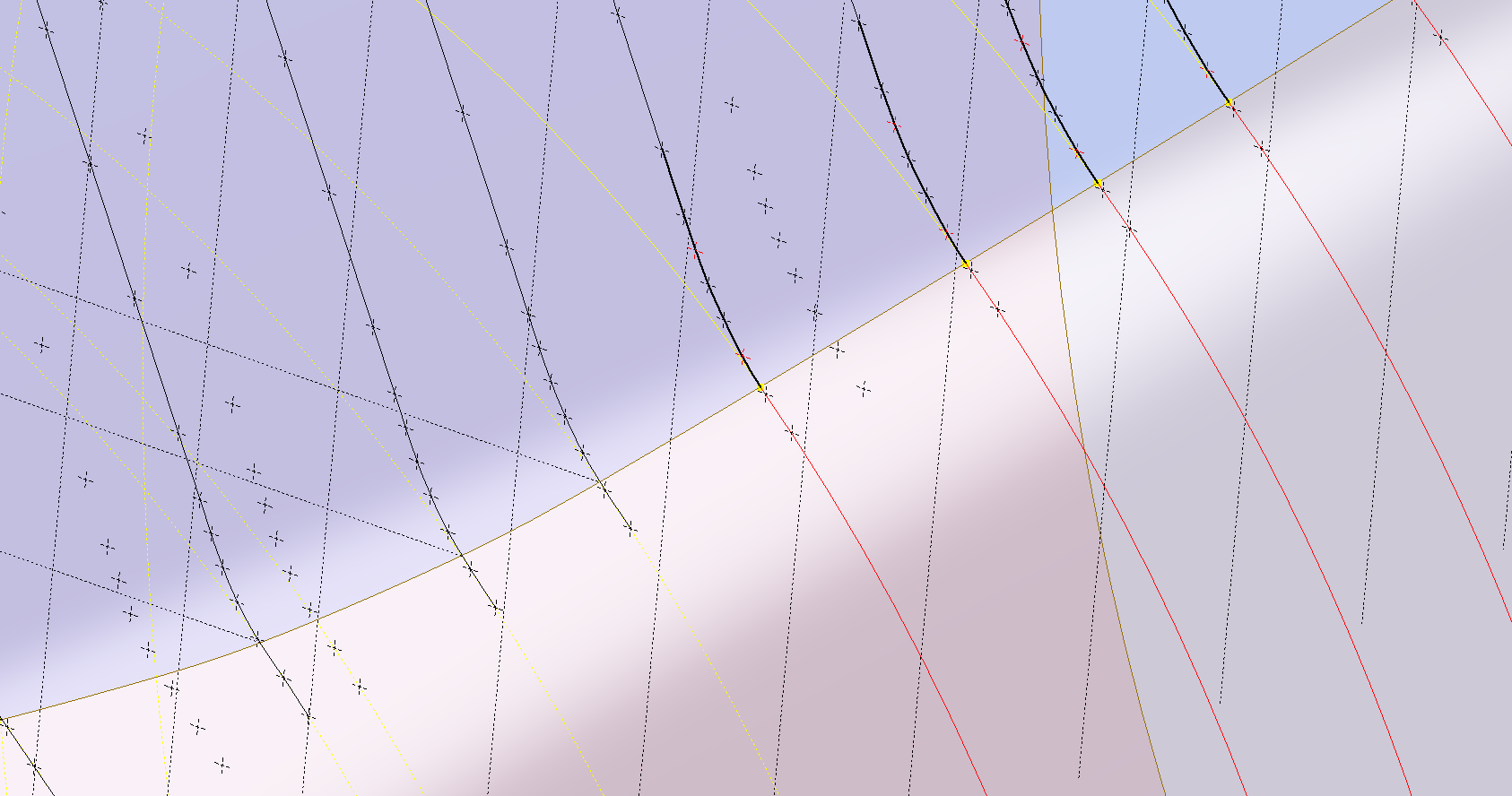
Depending on the aircraft manufacturer, the canopy contour lines may not align exactly with the fuselage because the canopy surface is typically offset from the fuselage surface, which is reflected in the information provided. For the P-47 you can see the ordinate points are an exact match with coincident curves from the fuselage surface therefore the tangent line is actually defined by the intersection between the canopy contours and the fuselage contours.
Initially, when I started this study, I profiled all the ordinate points for the canopy and compared this with the fuselage surface, revealing a minor discrepancy. The thing is we don’t have to fully connect all the coordinate points for the canopy, just the points above the intersection line.
First, we need to define the actual definition of this intersection on the fuselage surface which will be transposed to the canopy model. We take the vertical dimensions from the fuselage centre as defined on the canopy ordinate drawing #89F11456 and create a sketch which will be lofted to split the fuselage surface. On the second image above you will notice a number of prominent points on the upper curve profiles. These ordinates are not shown on the early P-47D drawing but are shown the on the later P-47D and P-47N ordinate layouts.
Initially, I opted for a tangent spline curve to complete the main circular profile of the fuselage bulkheads as per the ordinate drawing thinking that the relevance to the finished profile was nonessential. However when I compared the first run of the canopy and fuselage alignment studies I found that it was necessary to include those additional ordinates which are now included in the spreadsheet record.
These images show I have opted to correct the minor discrepancy by only profiling the canopy to the actual intersection line. I should note the Canopy and Fuselage are separate CAD models which means I can derive the surface from the fuselage model and manipulate it as required in the canopy model without affecting the original. For each canopy station, I projected a section thru the fuselage surface which gave me a spline to which I could add a tangent constraint when profiling the canopy lines. The images show the initial interpretation of the canopy profiles and the corrected profile in red (construction geometry omitted for clarity).
Tech Tip: if we had instead derived the station sketches from the fuselage model and then projected this in the canopy frame sketches as an outline we would not be able to add a tangent constraint. This is a limitation with Autodesk Inventor when working with splines and the workaround is to project a surface cut section as I have done above.
For each canopy station, I am only sketching the ordinates down to the intersection line with the fuselage and adding a tangent constraint to the projected fuselage profile curve. Because we split the fuselage surface we will have a point at the split that we can use in the profiling of the canopy frames.
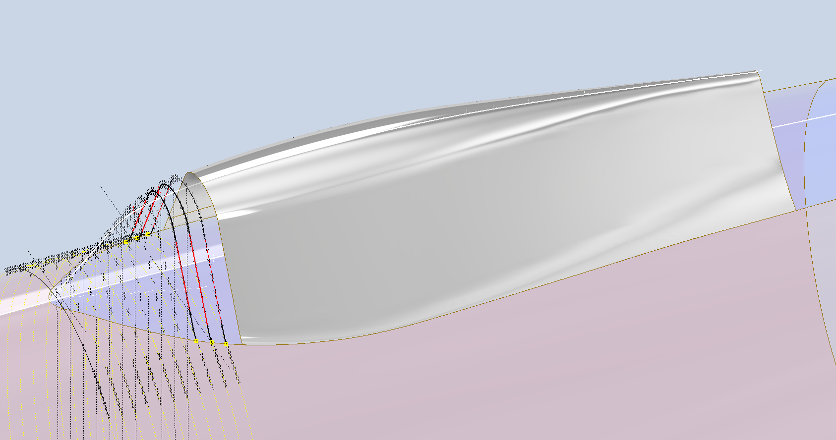
The actual skirt for the canopy obviously overlaps the fuselage surface and therefore we will have to define the edge relative to the tangent intersection line. As mentioned before we can manipulate the fuselage surface that is derived in the canopy model which means we can trim that to suit without impacting the fuselage model.
The tricky bit is ensuring that the edge of the skirt is exactly the same dimension from any point along the intersection line and this is how I do that.
The first thing to do is create a work plane perpendicular to the intersection line and draw in a partial curve and then sweep this along the intersection line path. The reason for this being a partial curve and not a full circle is because there is a tight radius at the front edge of the canopy which may not be possible to traverse using the sweep command if this was full circle.
When this is done it is a simple exercise to trim the derived fuselage surface to obtain the skirt surface.
By creating a curved sketch and sweeping along a curved profile we ensure that at any point along this path, the distance to the resulting edge is exactly the same. A similar technique will be employed to develop the finished edge of the glass panel models.
I still have some work to do on the windscreen portion of the front canopy and then I will fully model the structural components.
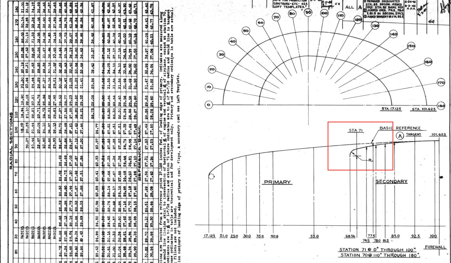
The Ordinates for the P-47 Cowl are listed on Republic Drawing #89P63300 for P-47B, C and D. They differ from the usual ordinate dimensions that usually comprise X and Y coordinates in that they are radial ordinates. Essentially dimensions along a radial axis that are subdivided in 10-degree increments from 0 degrees to 180 degrees.
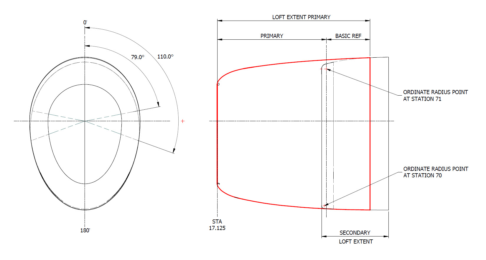
The ordinates as usual are extrapolated to a spreadsheets where I have also converted the radial ordinates into X,Y coordinates should this be required. The highlighted dimensions are the points on the inside face of the cowl skin. The dimensions at Stations 70 and 71, bordered in red, are to the centre of the secondary cowl leading edge radius at each degree increment. To be precise this is actually the profile for the Preheater.
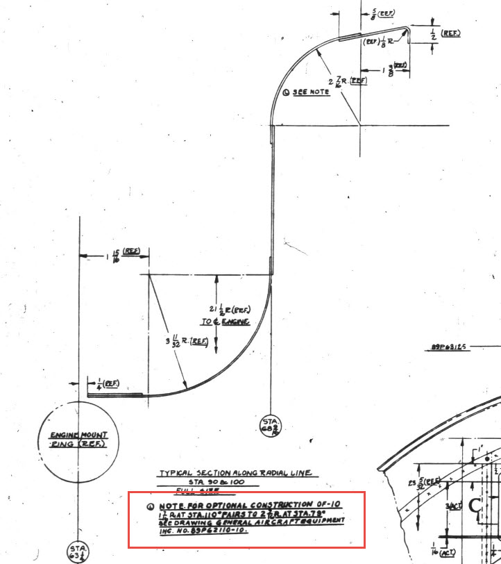
The edge radius at the top of the Preheater is 2 7/16″ at Station 71 and 1 7/16″ at Station 70. On the Republic blueprint the radius of 2 7/16″ is applicable from 0 degrees to 100 degrees, and the radius of 1 7/16 ” is applicable from 110 degrees to 180 degrees. In the CAD drawing above, I have noted 79-degree and 110-degree intervals, and there is a reason for this.
At some point along this Preheater front edge, there is a transition from the 2 7/16″ radius to the 1 7/16″ radius. The republic blueprint for Preheater #89P621101 details the profile section that is applicable at 90 and 100 degrees showing the top radius at 2 7/16″ however it also notes an option where the radius fairs from 79 degrees to 110 degrees instead of 100 degrees to 110 degrees.
Personally, I prefer the latter as it ensures a smoother surface continuity. As you can see in the following image of a recent P-47 restoration they appear to have opted for the former which displays a noticeable bump from the 100 to 110-degree transition. The second image is the CAD interpretation of 79 to 110 degrees which is much smoother.
I have modeled only the main portion of the Preheater body surface; there is a projected curved section forward of this which I will model separately and again a good reason for doing this*.
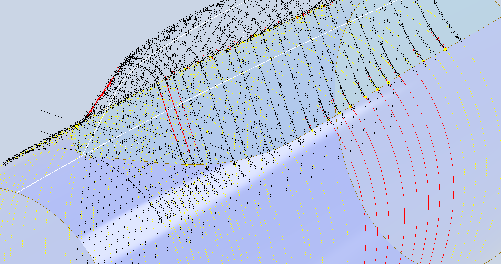
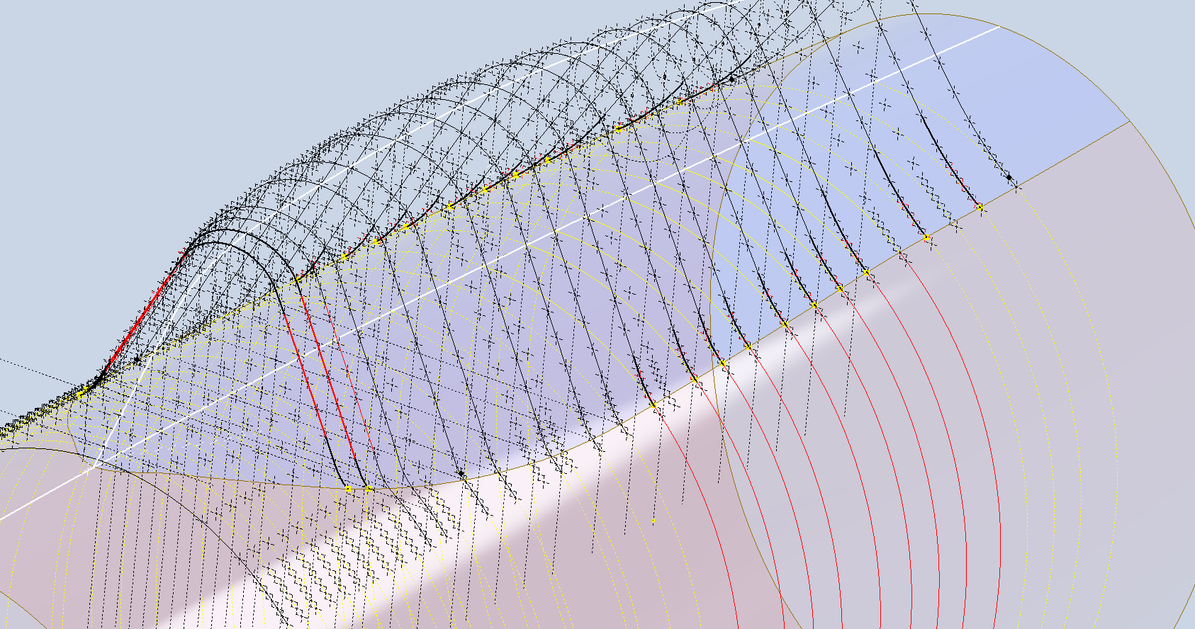
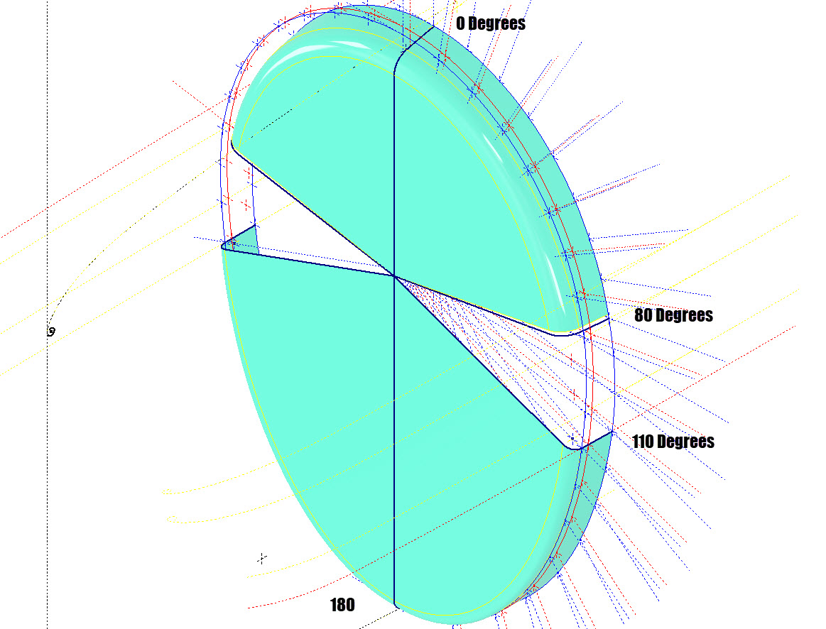
If we look at the CAD development of the Preheater surface model you can see I have developed the top profile with an ordinate radius of 2 7/16″ to the 80 degree increment and the lower section ordinate radius 1 7/16″ from 110 to 180-degree increment. However, when you loft the 2 profiles you can see the default curvature transition is not continuous…what we want is for the curved section to have smooth continuity throughout the transition.
I should note that the surface was developed to the 80-degree increment and then trimmed back to 79 degrees; I already had the construction sketches in the model…just saves some work.
Inventor like other CAD software will attempt to interpret the desired surface loft but it does not always achieve the desired result. This is easily corrected by selecting transition points within the Loft dialog which will enable a smoother transition.
Going back to my earlier comment on the projected curved section*; as per comments above; the CAD-interpreted surface may not produce the desired result with more complex geometry. So often the best way of doing this is to model that section separately ensuring finer control over the finished surface.
CAD Tip: The vertical face of this developed surface is flat, occasionally when lofting, sweeps or even applying a surface patch it is always a good idea to check the finished surface is actually flat and planar where expected. The way to check that a surface is planar is to select the New Sketch option using the surface as a sketch plane…if the surface is planar it will allow a sketch.
P-47 Engine Mount:
On the Republic Drawing #89P62101 for the Engine Mount the intersection point of the top diagonal brace with the centre of the front ring is not clear.
On the Front View, we have either a dimension of 8.75″ (1) or an Angle of 58.5 degrees (2). To verify which is the correct set out for the top brace we turn to the elevation view. Here we have a cross brace intersecting the top diagonal at 20 21/32″ (4) and 16.592″ (3). Drawing in this intersection point in conjunction with the known datum at the extreme right we project the centre line of the brace to intersect with the front ring.
This projected point is within 0.017837600 mm of the point determined by the dimension 8.75″ (1) and 1.057782238 mm where the angled line (2) intersects with the ring centre. This verifies that the actual point of intersection is the dimension 8.75″.
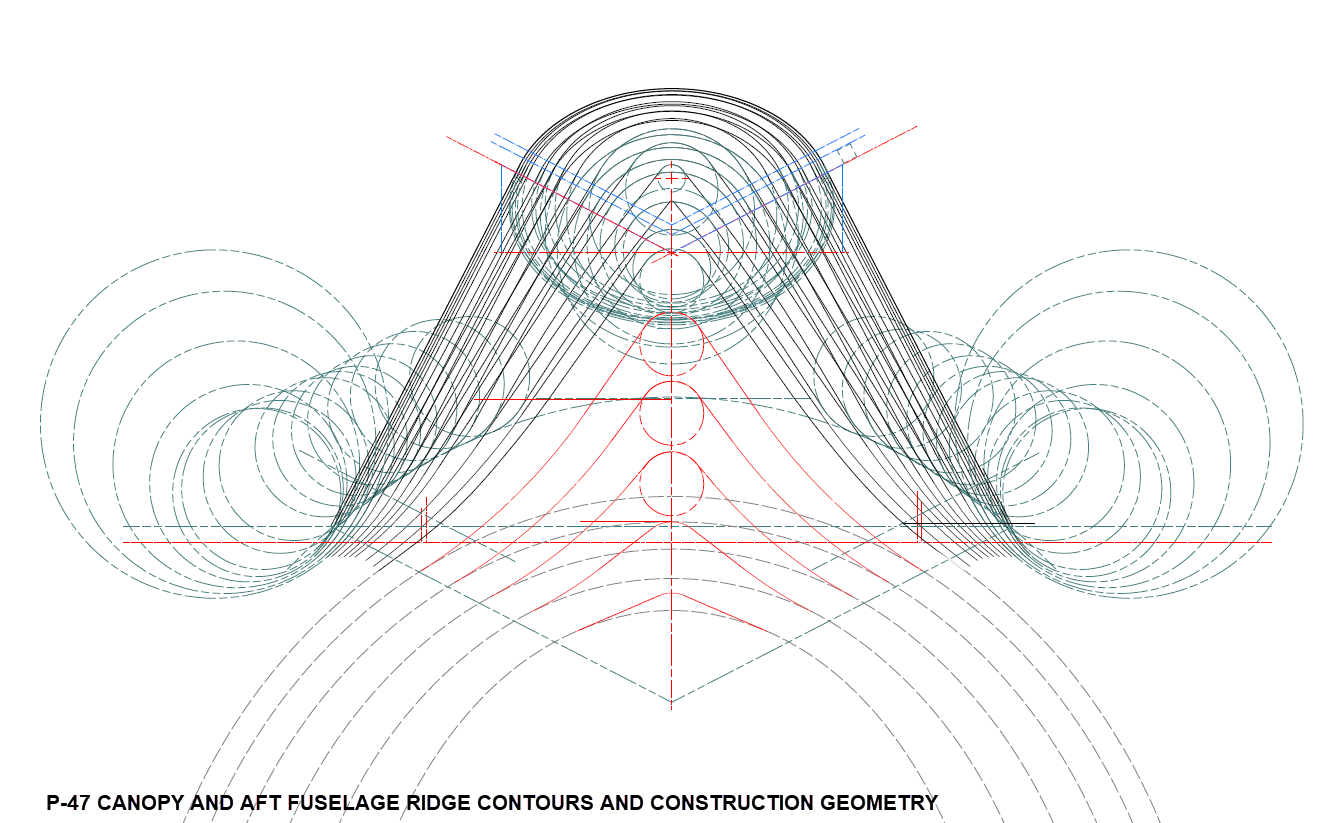
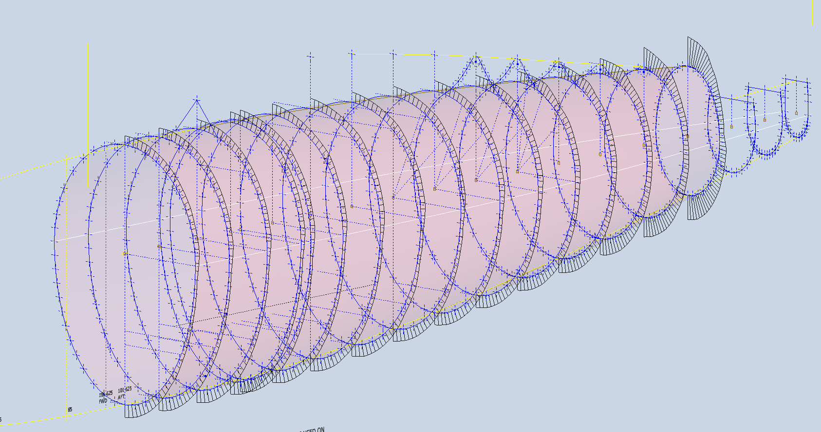
P-47 Fuselage Curvature Analysis:
The following image shows the curvature analysis at each station of the fuselage. Only 4 rogue points were micro-adjusted to align correctly. What we are looking for here is not perfection but consistency. You will notice a small flattening of the side curves around the centre of the fuselage, which is fairly consistent throughout. The primary reason for doing this is to identify any points that will create a negative curvature or completely in the wrong position.
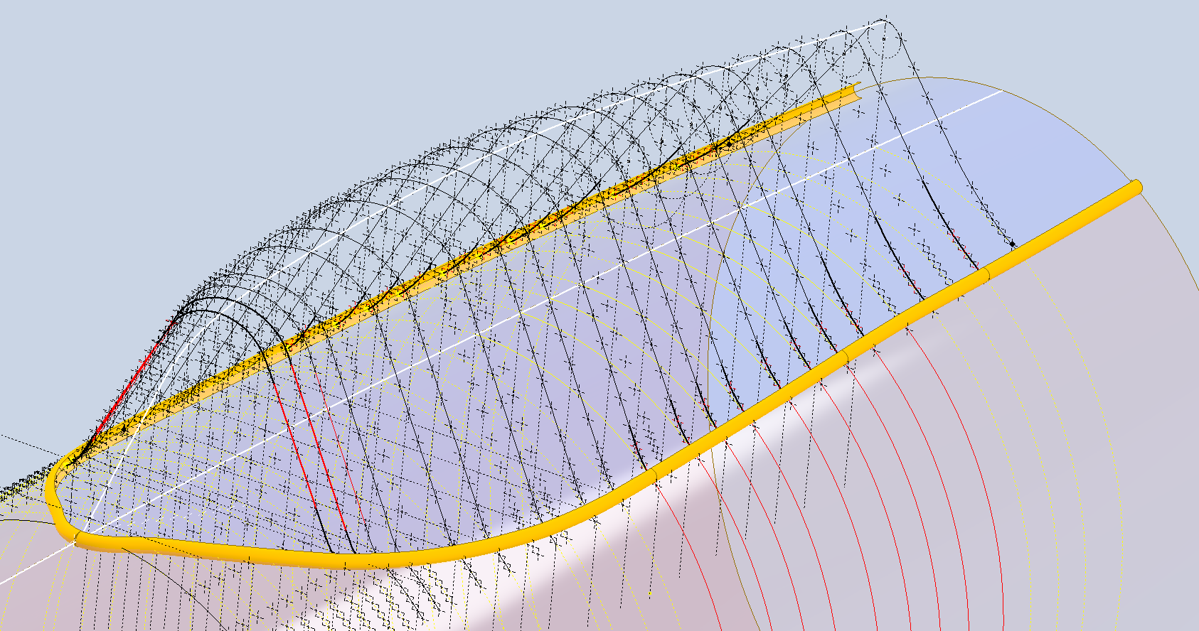
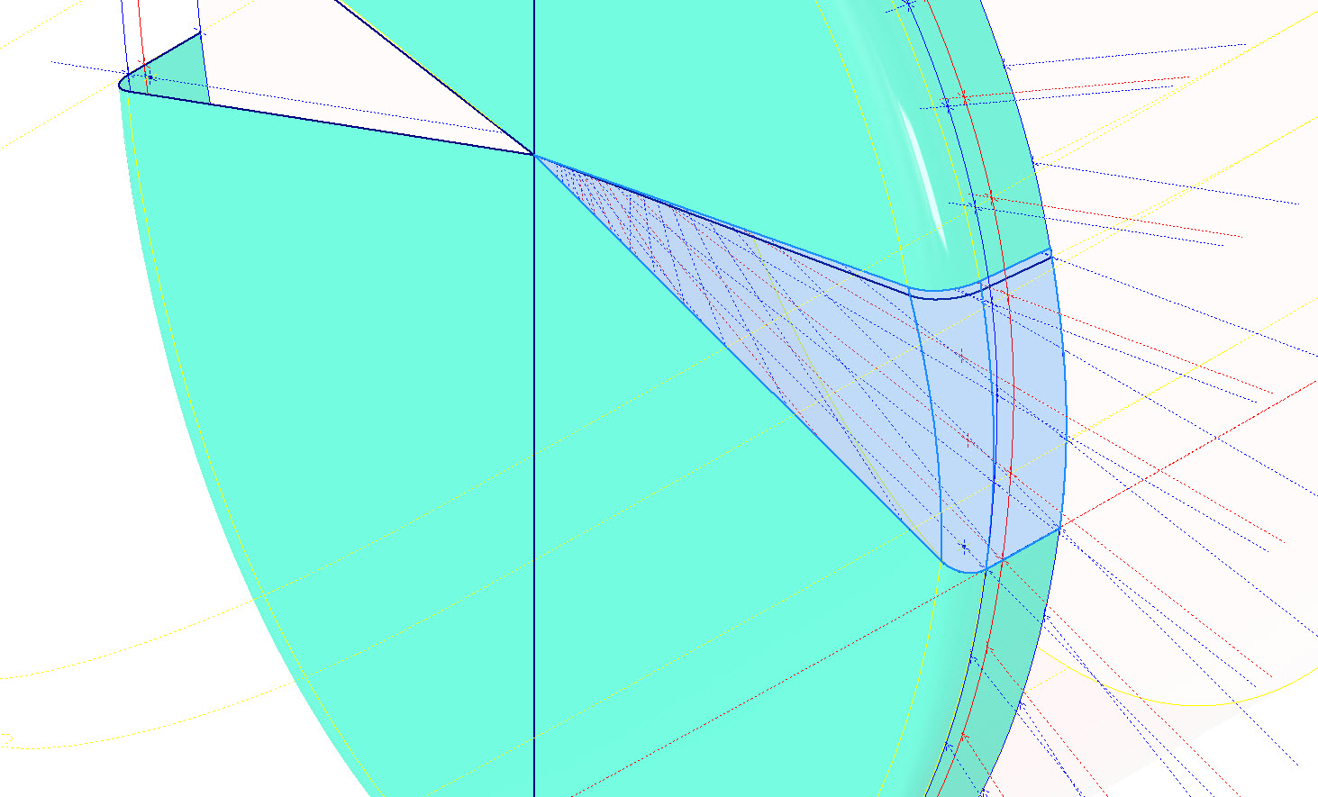
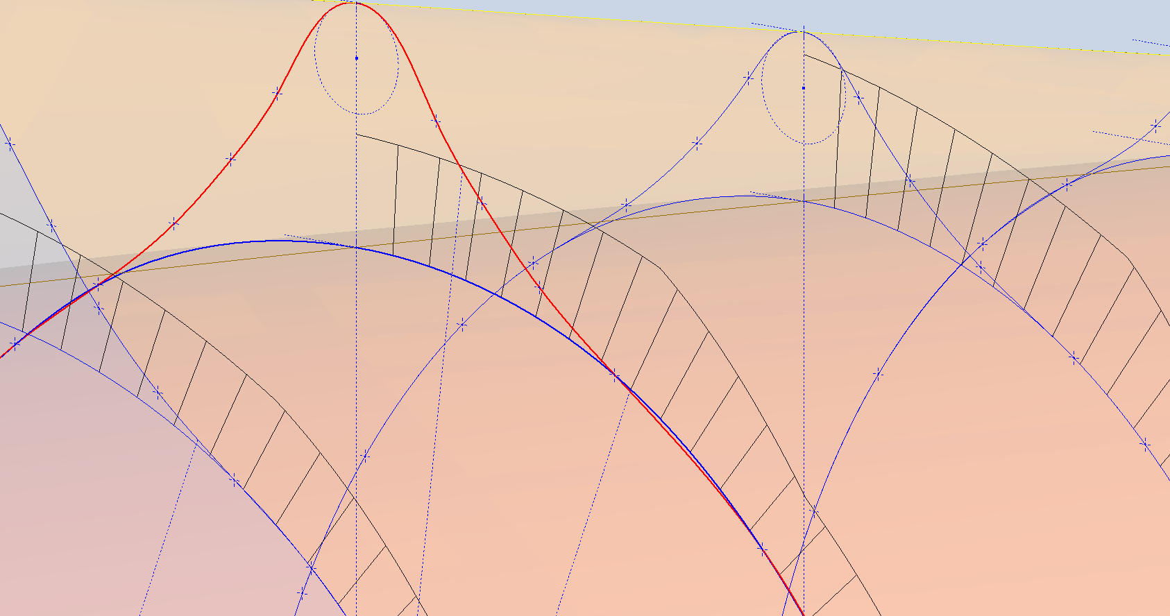
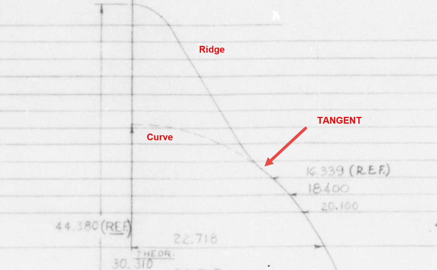
The next challenge is to identify the correct tangent points between the humped back ridge curves and the main fuselage. It may tempting to just profile a spline connecting all the points from the ridge curves and the main fuselage but this is likely to create small imperfections where the tight curves meet the main body profiles…so it is always best to do this separately.
In the first image above the red line is the best fit spline connecting all profile points and you can see how it dips below the curved profile from the blue main fuselage curve profile. From the Republic ordinate drawing it is clear the intent is for the ridge profile to be tangent at the point of intersection.
The finished profiles will look something like this…
The P-47 project has now incorporated the Canopy Basic Layout. This Basic Layout represents the surface derived from the table of ordinates, with dimensions that reflect the mold lines at the inner face of the skin. An allowance of 1/32″ is required to accurately represent the actual surface of the canopy glass. All ordinate points are provided in an Excel spreadsheet, as is customary.
Once the best-fit surface is determined, it undergoes a curvature analysis to check for low and high spots. The next part of the process is checking the alignment with the fuselage’s basic layout surface. The Table of ordinates includes the Waterline level for the tangency intersection point between the canopy surface and fuselage at each station. The dashed lines along the lower level of the canopy profiles represent this waterline.
Each tangent point in turn is then checked against the fuselage’s basic layout surface. As expected, there is some minor deviation which is less than 0.3mm which is within acceptable parameters. Of course, with CAD it is technically possible to get this absolutely exact (see next blog article for solution). The primary reason for doing this check in the first place is to ensure we don’t have any rogue ordinates that could create problems later on.
A similar exercise will be undertaken for the forward canopy section and windshield. When we have a satisfactory basic layout surface for each section of the canopy I will endeavor to profile the glass panels and supporting structural elements.
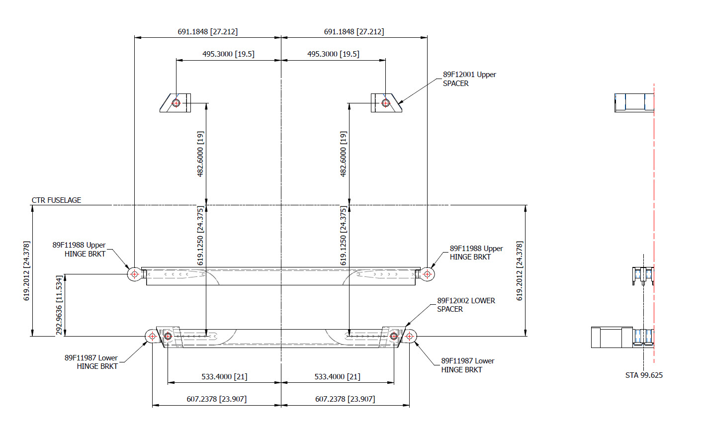
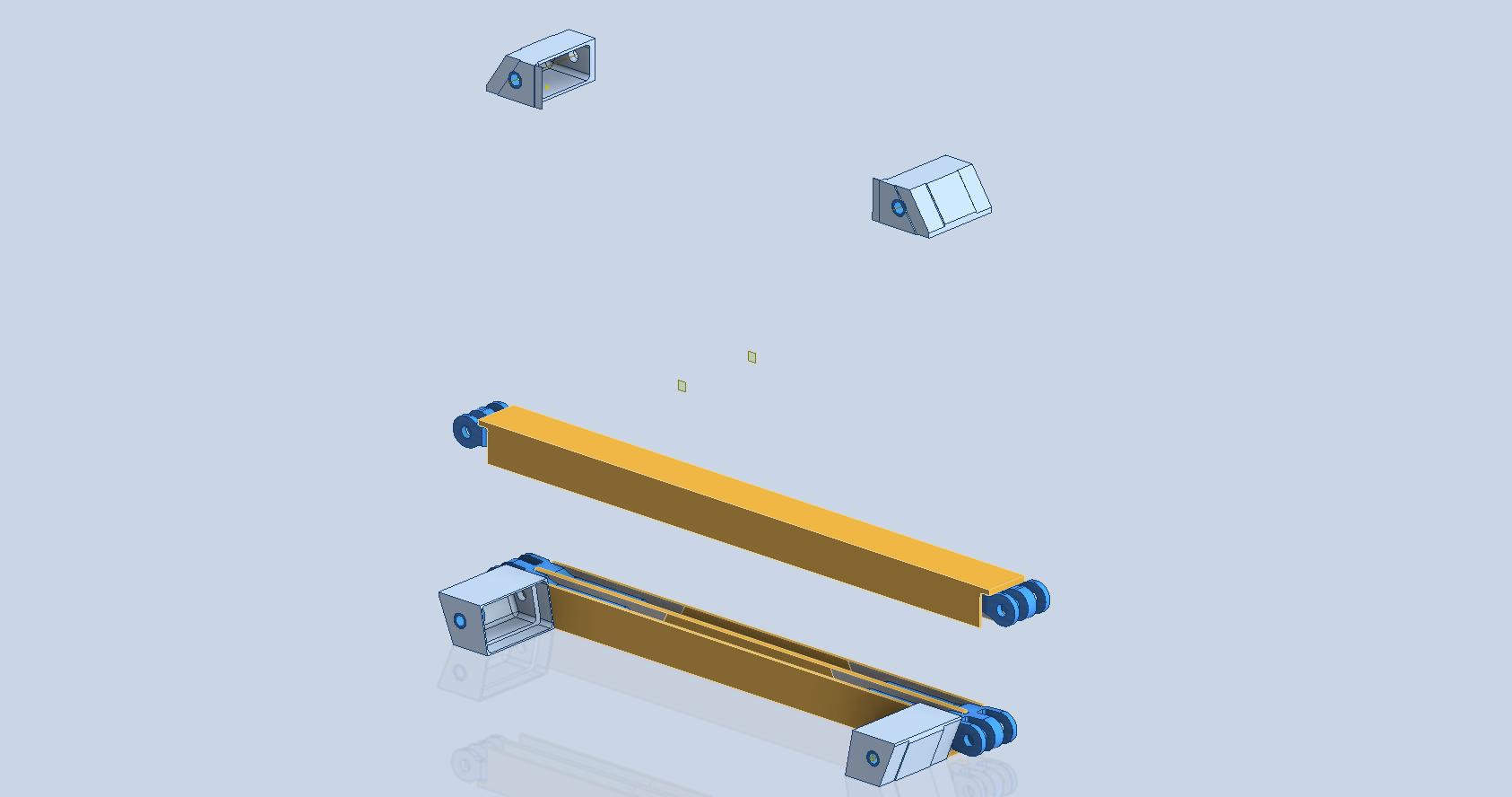
P-47 Cross Tie Wing Hinge/Engine Mount:
This is the preliminary arrangement for the Cross Tie that supports the Wing Hinge and Engine Mounts. A small point worth noting is that the actual vertical dimension to the Wing Hinge Centre is 24.378in, and the dimension to the lower datum point for the Engine mount is 24.375in. A small variation, almost imperceptible but nevertheless important. This is the reason why the matching holes from the Lower Engine Mount are to be match-drilled through the Cross Tie and not pre-drilled in the Cross Tie. Once I have established the final location for the wing I will cross-check the hinge locations to verify setting out dimensions.
Grumman Goose Update:
The Grumman Goose is already available as an Ordinate package (See CAD/Blueprints page) which though comprehensive excluded the Nacelle. While I await some information on the P-47 I jumped back into the Grumman Goose project to partially develop the Nacelle and general tidy up of the package as a whole.
The Grumman Goose is not my primary project but as I find time I will drift back to the project to apply updates. I will also do several analysis exercises on the fuselage and wing surfaces to check curvature and alignments. This will be an ongoing project over the next few months. If you have previously purchased the currently available Ordinate package for this aircraft I will send you the updates when they are complete.
Feedback, questions, then please get in touch: hughtechnotes@gmail.com
The JB2 project is progressing quite well, with most of the structural elements in place. I will be doing a lot more detail work on the surface skin and, of course, adding the main support elements for the engine structure. In the interim, I thought it may be prudent to post a few images of the project for your perusal.
Comments or inquiries as usual to hughtechnotes@gmail.com.