North American P-51 Mustang: Fuselage
The drawing archive I have contains quite a large selection of legible fuselage frame drawings which I am collating according to the Station reference on the fuselage. I have a spreadsheet that lists all the Mustang drawings including the original drawing number, the scan image number and location within the archive.
Each fuselage frame at each of the designated stations may comprise 3 or more elements, which unfortunately are scattered throughout the many rolls of scans thus requiring some exhaustive work with the spreadsheet data-sets to sort the numbers and folder locations in order to identify and collate the required frames for each assembly per aircraft type.
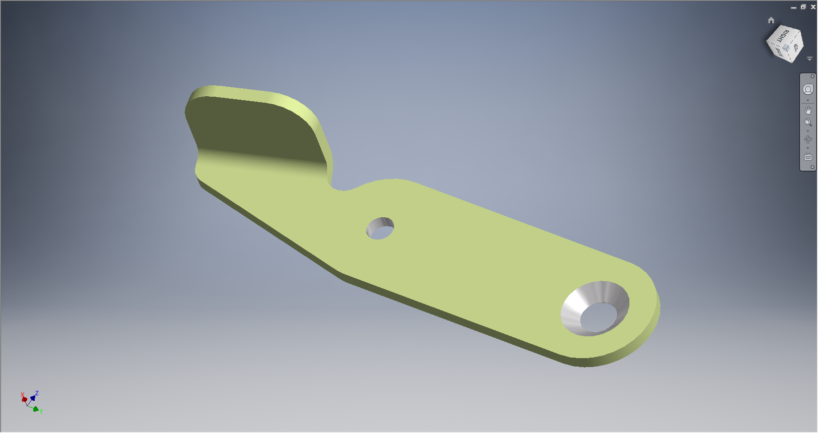
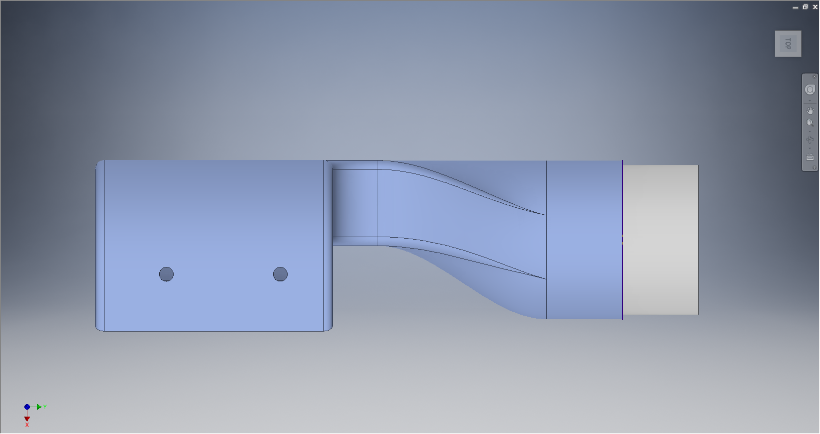
One such frame was at station 216 which I decided to model; partly due to the fact I was getting fed up looking at and sorting spreadsheet data.

There are several methods to modelling this and whilst I was subject to the vagaries and still limitations of the Inventor product (Solidworks has more options for working with splines) I developed a workflow that obviates some of these limitations and also how the end product is finished.
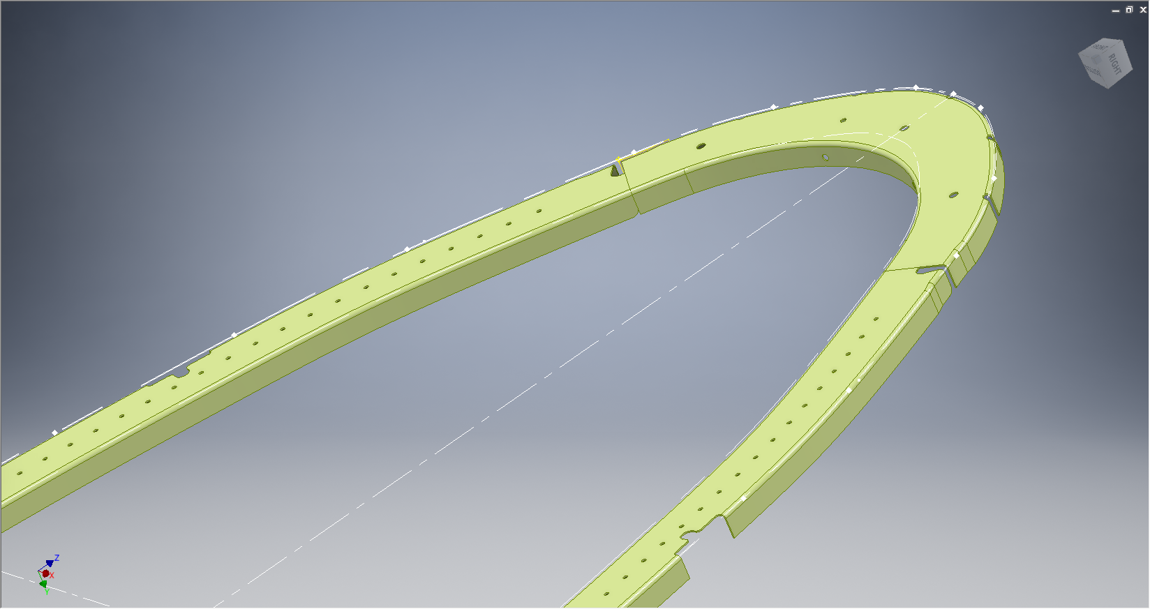
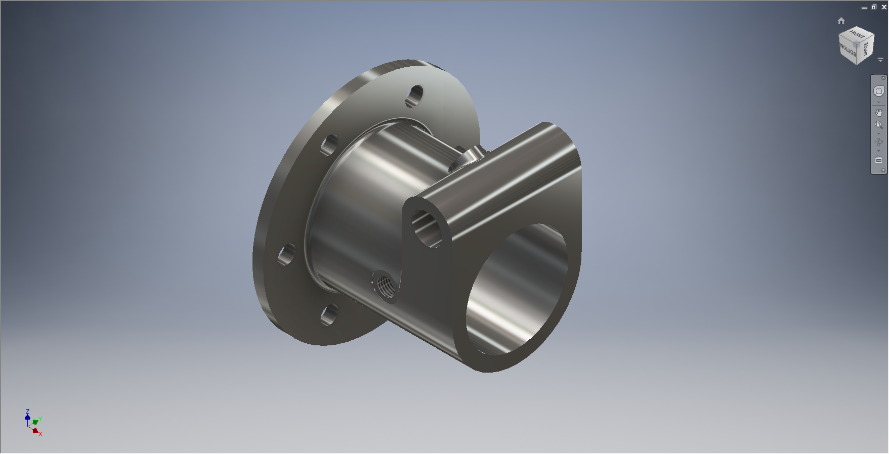
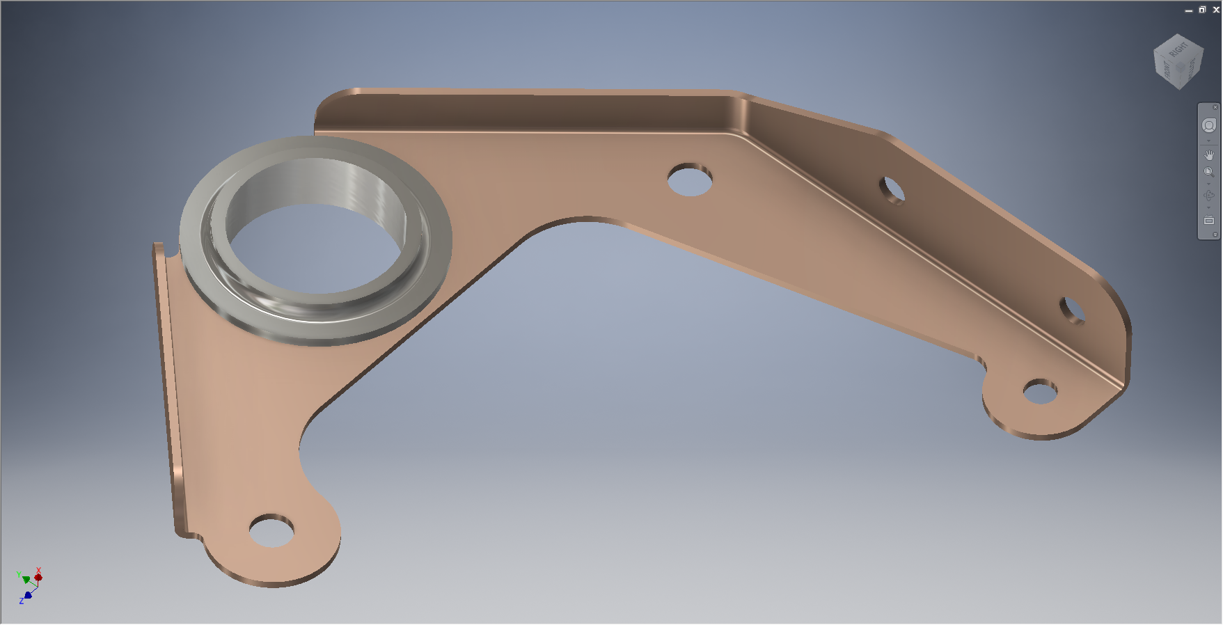
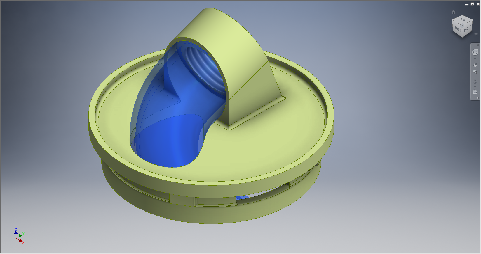
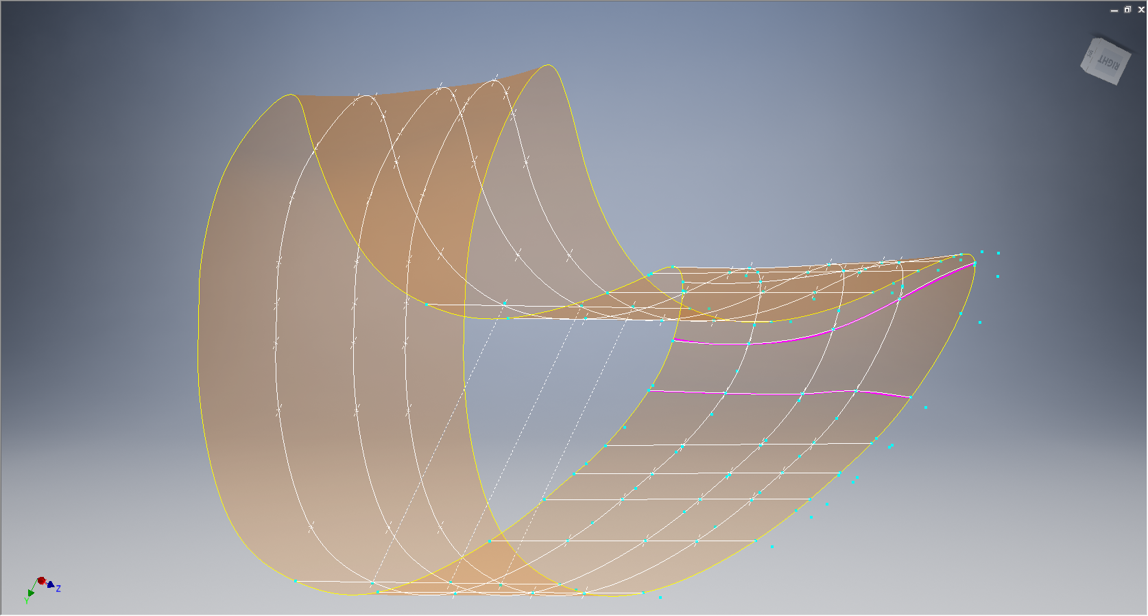
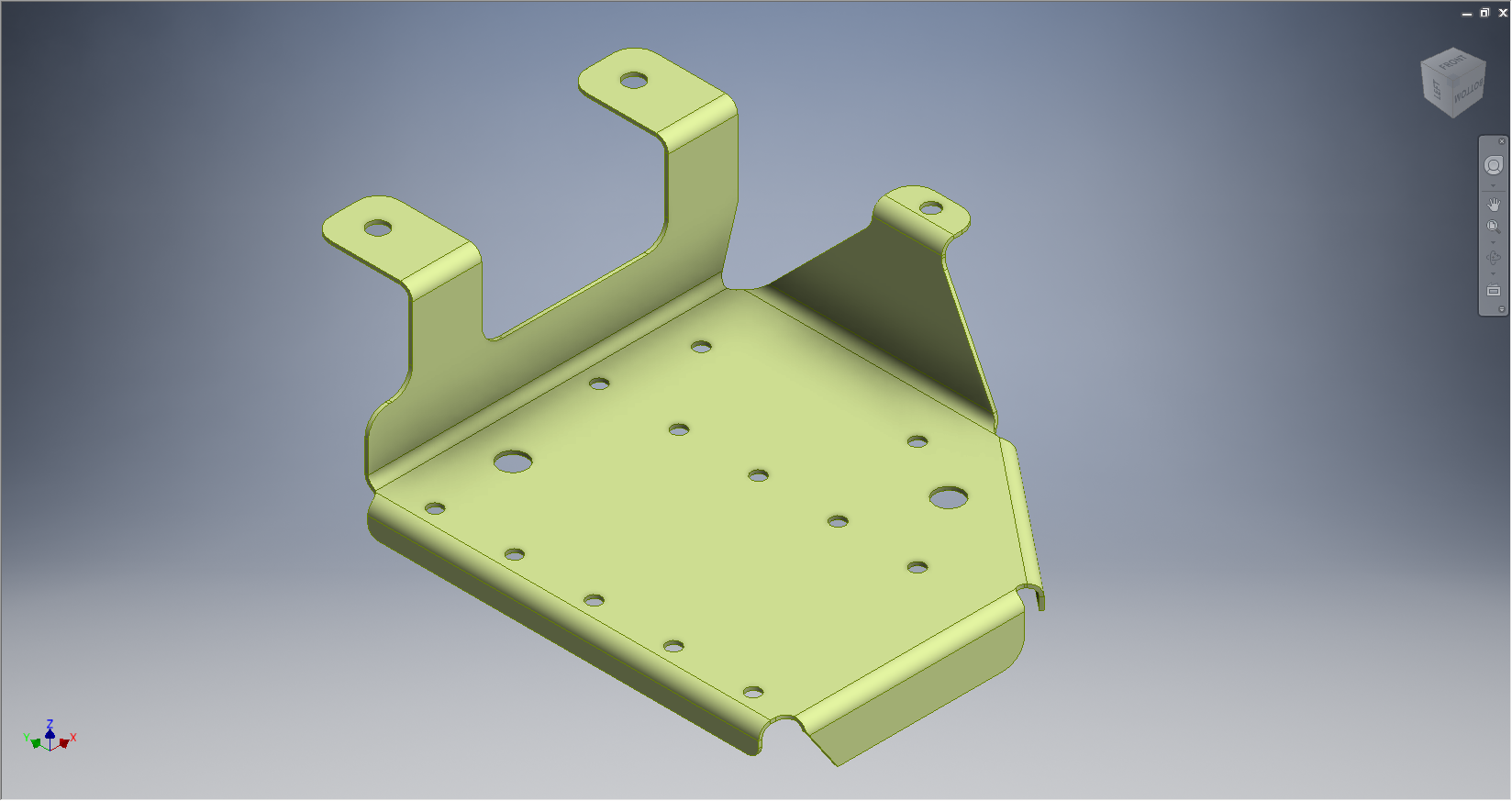
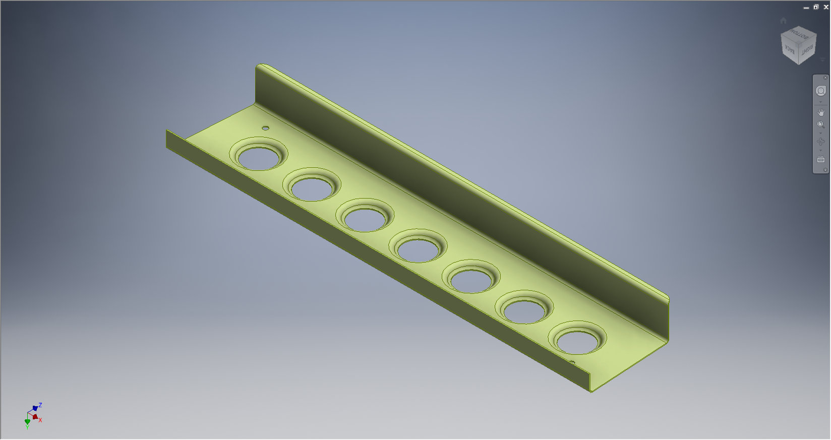
One way of doing this is to simply create a surface for the main plane and then project a flange line along the edge to create a”folded” surface and then apply thickness but this method gave some unusual iterations in the smoothness of the fillets at the end of the profile. I found that the best way is to create surfaces for all six faces; the splines inside and outside, the top and bottom planes and the ends, then sculpt to create a solid.
I would then go out about creating the notches and cutouts in the solid and then shell the solid to the required thickness. This works very well and ensures the integrity of the original spline ordinate lines (which would have to be split to do this any other way). This method also maintains better continuity of the end fillets and curvature (image 2).
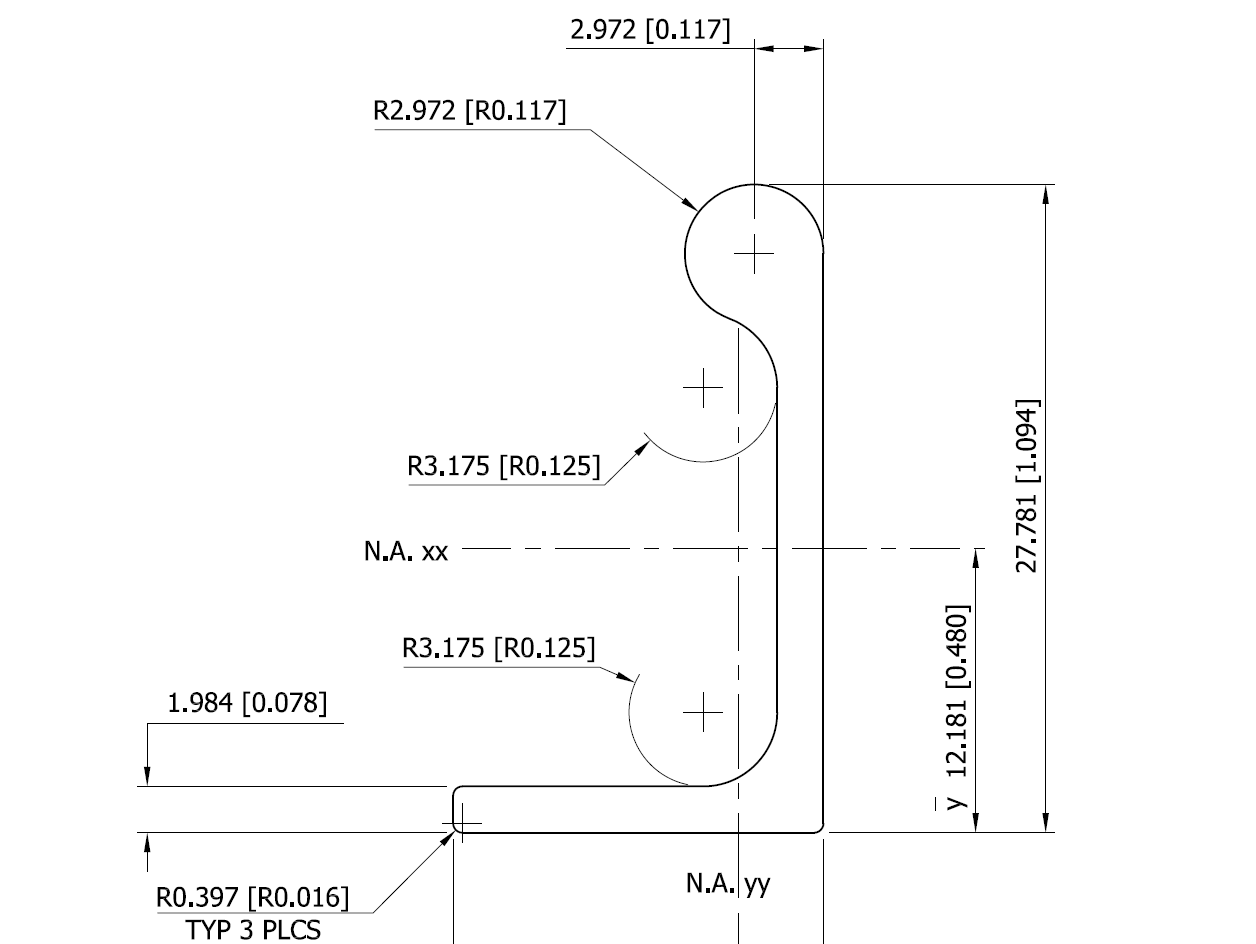
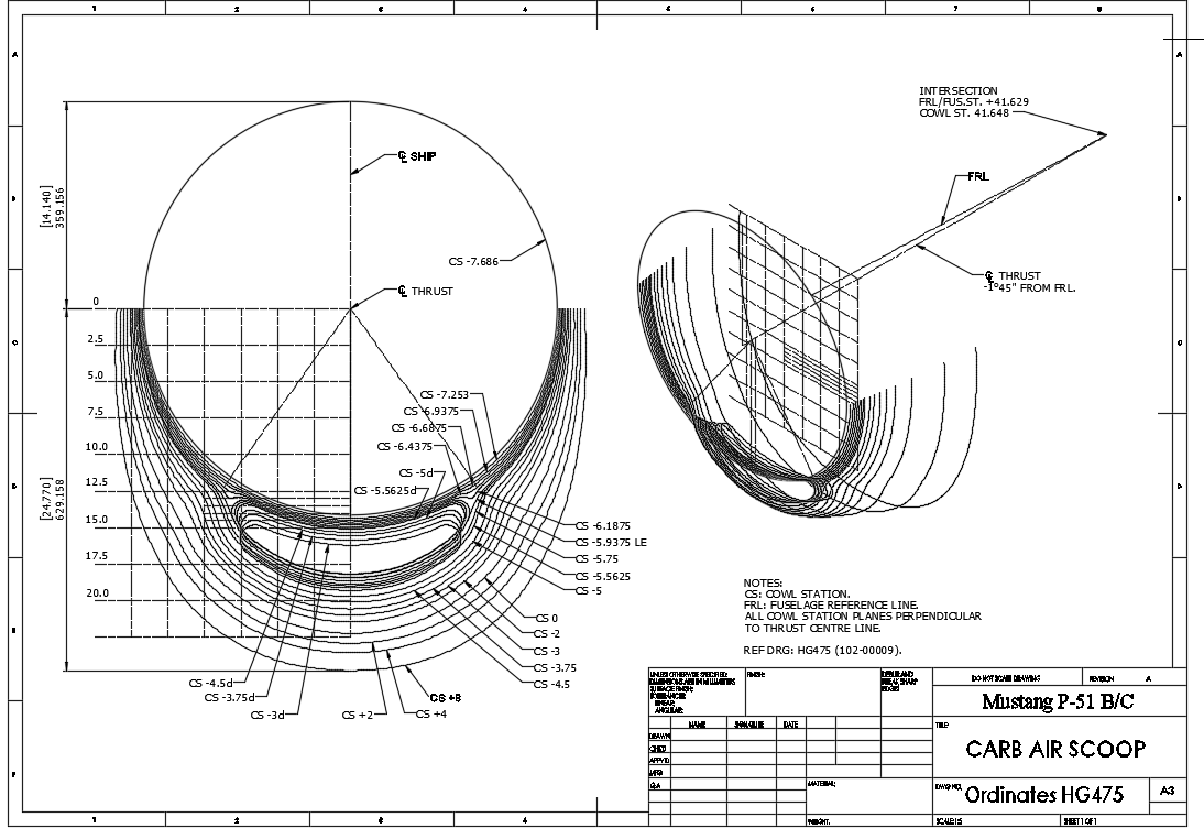
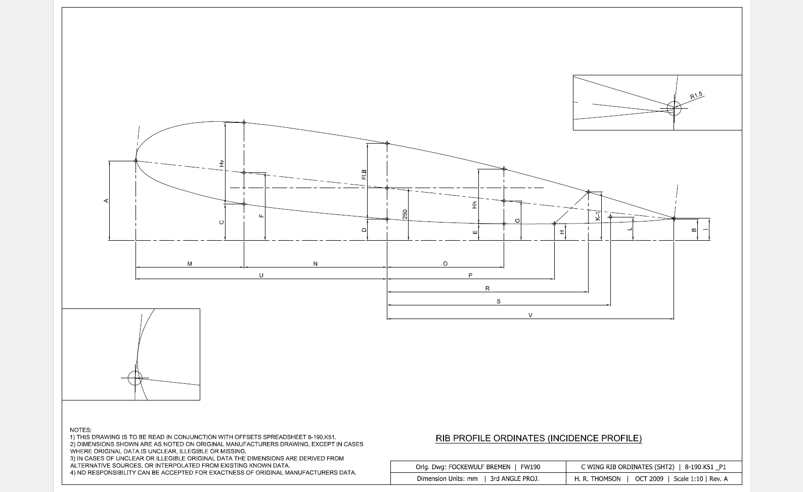
The frame drawings reference the mold line ordinates, which I have for the P-51 B/C Mustang variants.The P-51D is similar with the exception of the ridgeback on the main rear fuselage that has been reduced above the +10″ W.L.
Techy stuff: I mentioned a limitation in the Inventor software which relates to creating a line perpendicular to a spline. In Solidworks you just sketch the line and constrain it perpendicular to the spline, but you cant just do it this way in Inventor (as far as I know). What I did was use sketch construction lines to define the point of intersection with the spline that I wanted the perpendicular line to start from. As I already had a surface projected from the mold frame spline (for above construction) all I had to do was create a new plane perpendicular to this surface at the selected point. It was then quite simple to create a further sketch to define the line I wanted perpendicular to the spline at the correct location.


