NAA P-51D Mustang: Tail Wheel Down Position Support; Derived Parts (Inv)
I mentioned in an earlier post that we don’t have many of the forgings/castings for this aircraft but the few that we do have are not stated as such in their description and thus occasionally overlooked.
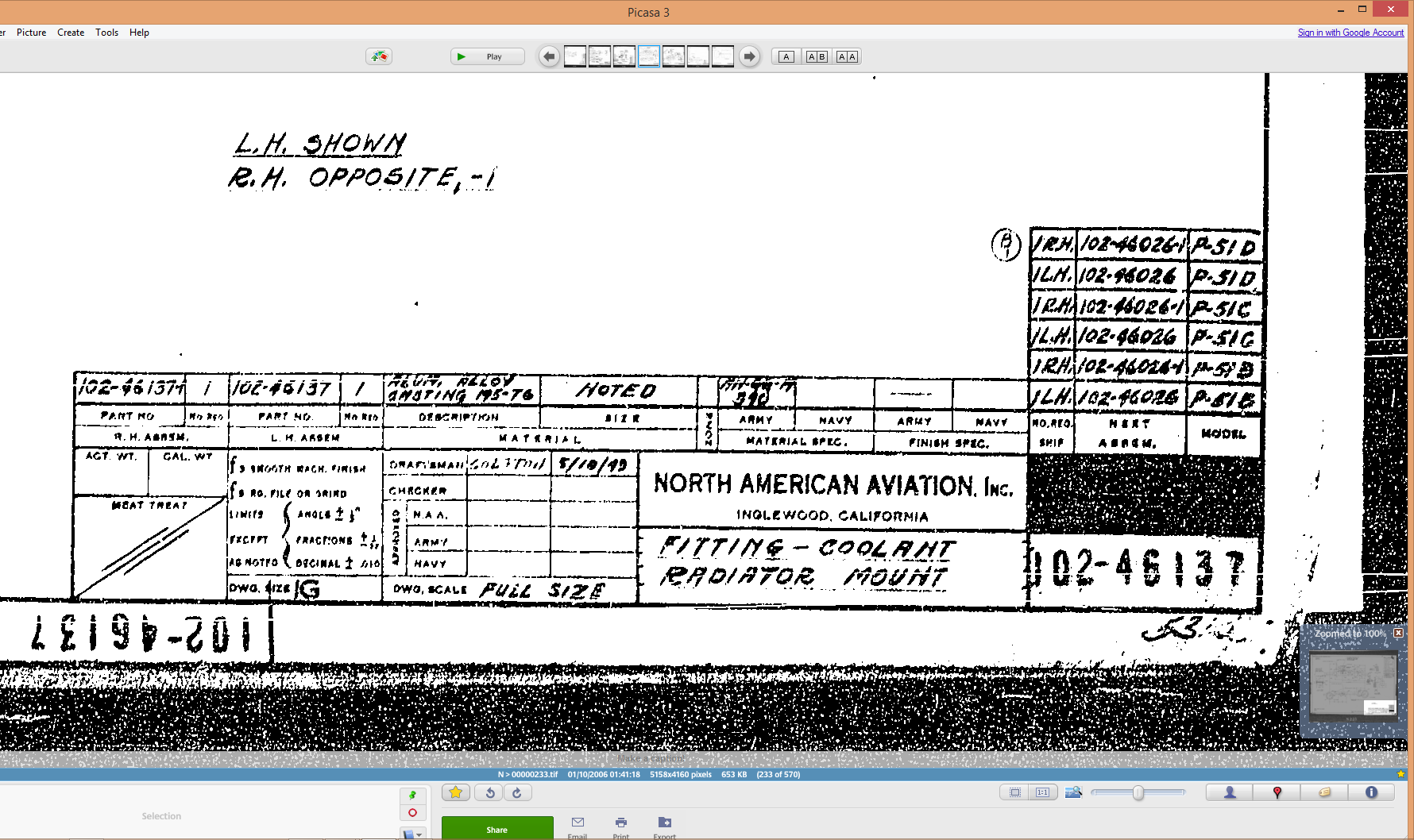
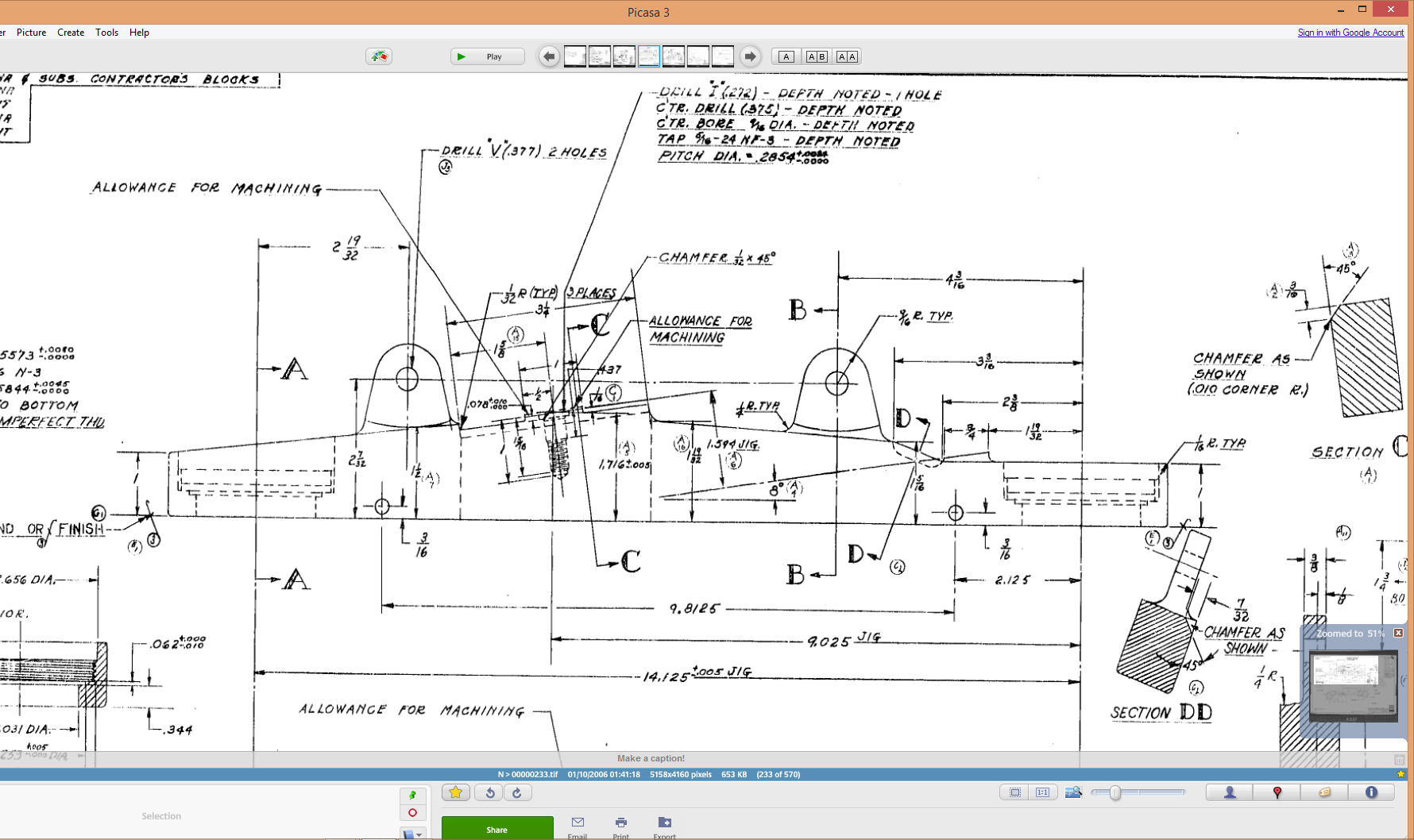
In this case the forging/casting was noted in the NAA machining drawing; which I do have. This gives me an opportunity to explain one of the strengths of the Autodesk Inventor product, namely derived parts!
Derived parts are a powerful but easy-to-use tool that comes in two basic flavors: you can derive a part from another one, or you can derive a part from an assembly. Using derived parts, you can easily create machining models and drawings from an as-cast model, and you can create a mold from the same model.


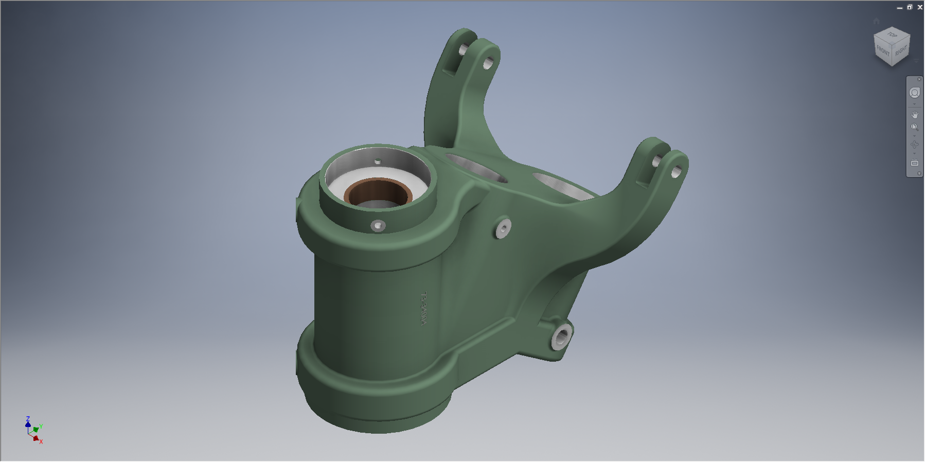
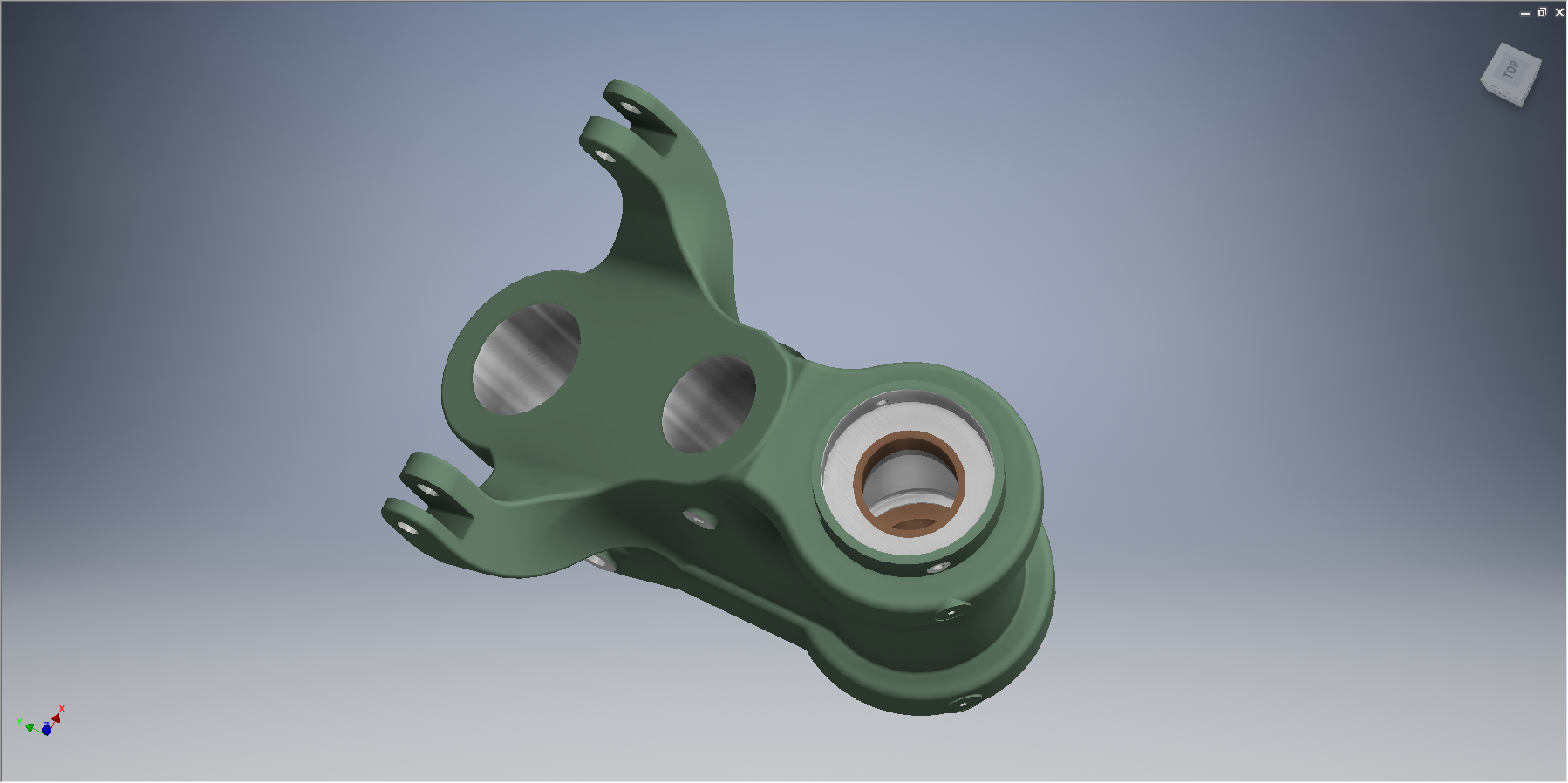
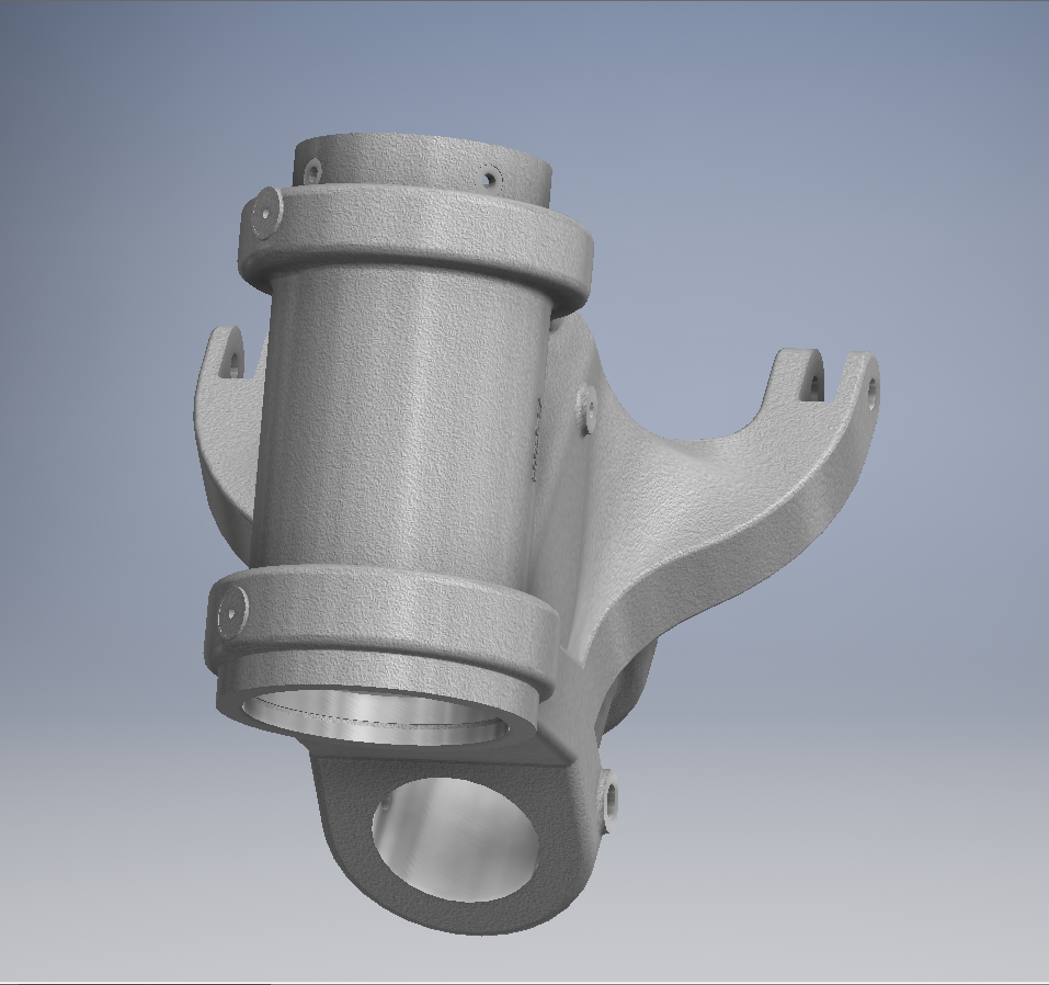
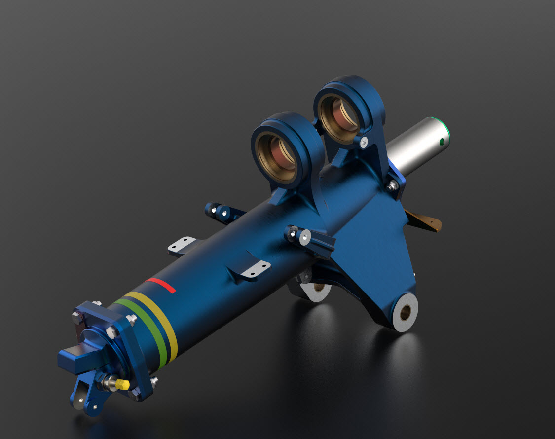
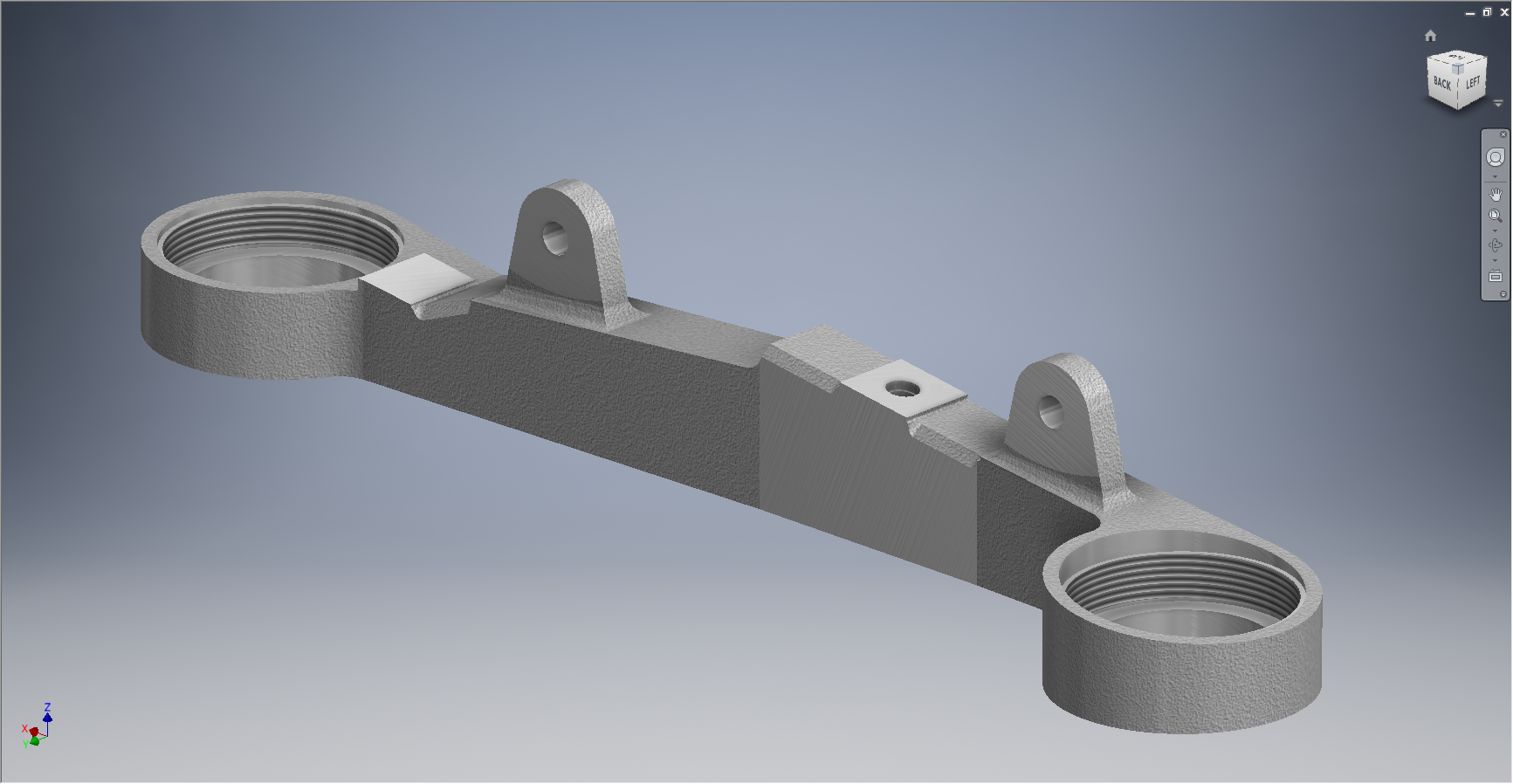
These images show the casting model I created from the original NAA drawing #73-34162 for the Tail Wheel Down Position Support.
This model took me quite a while to do due to the creation of all the fillets which got a bit crazy sometimes and I ended having to redo them several times to get them the way I wanted.


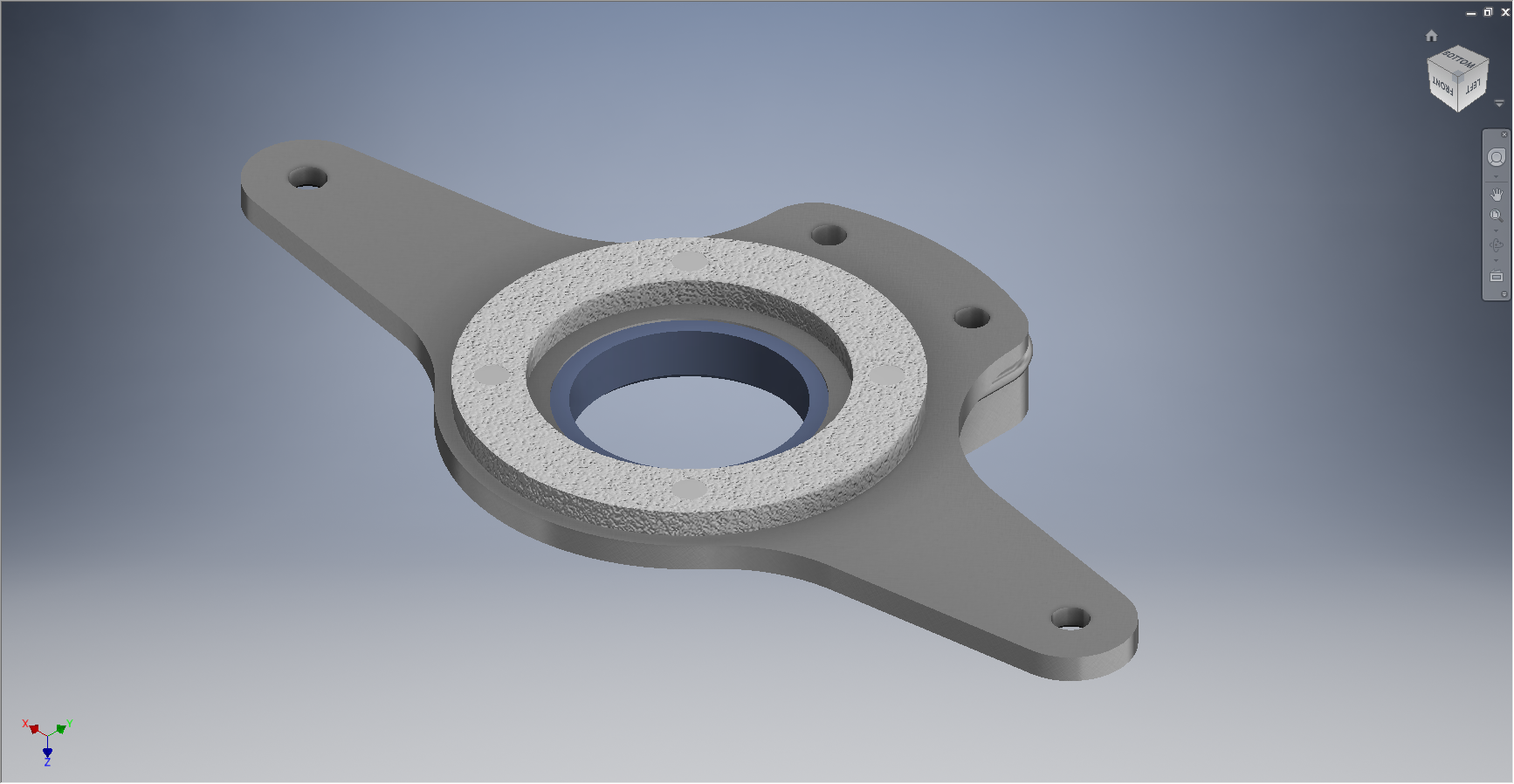
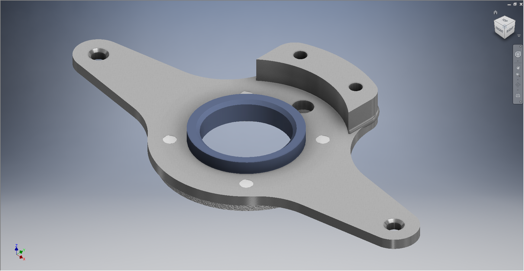
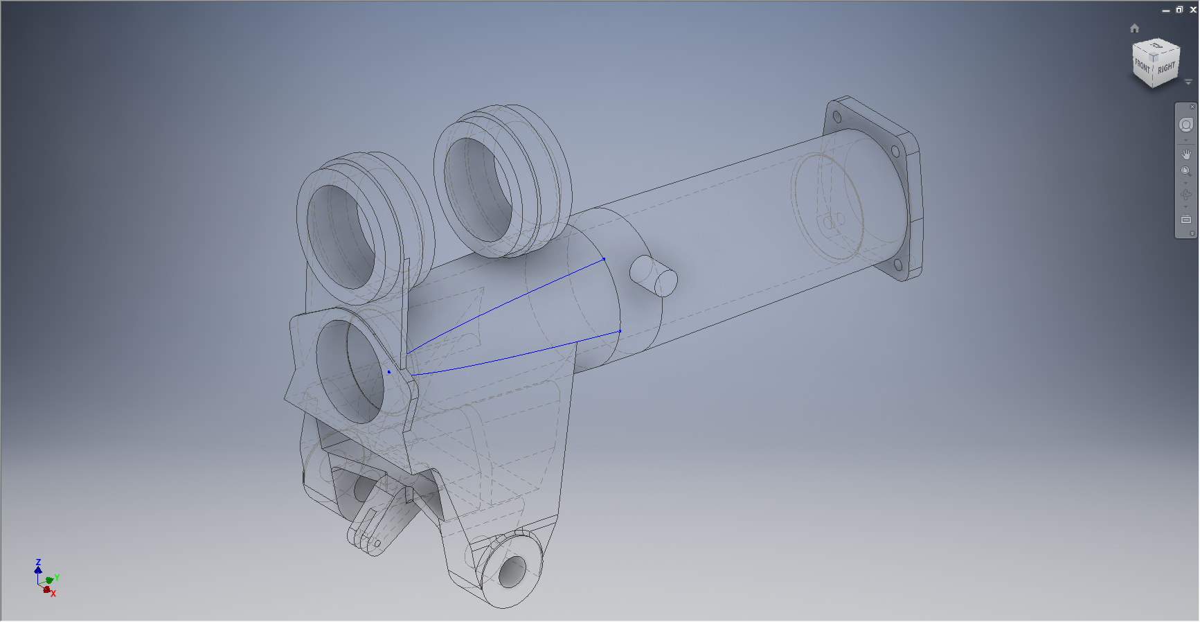
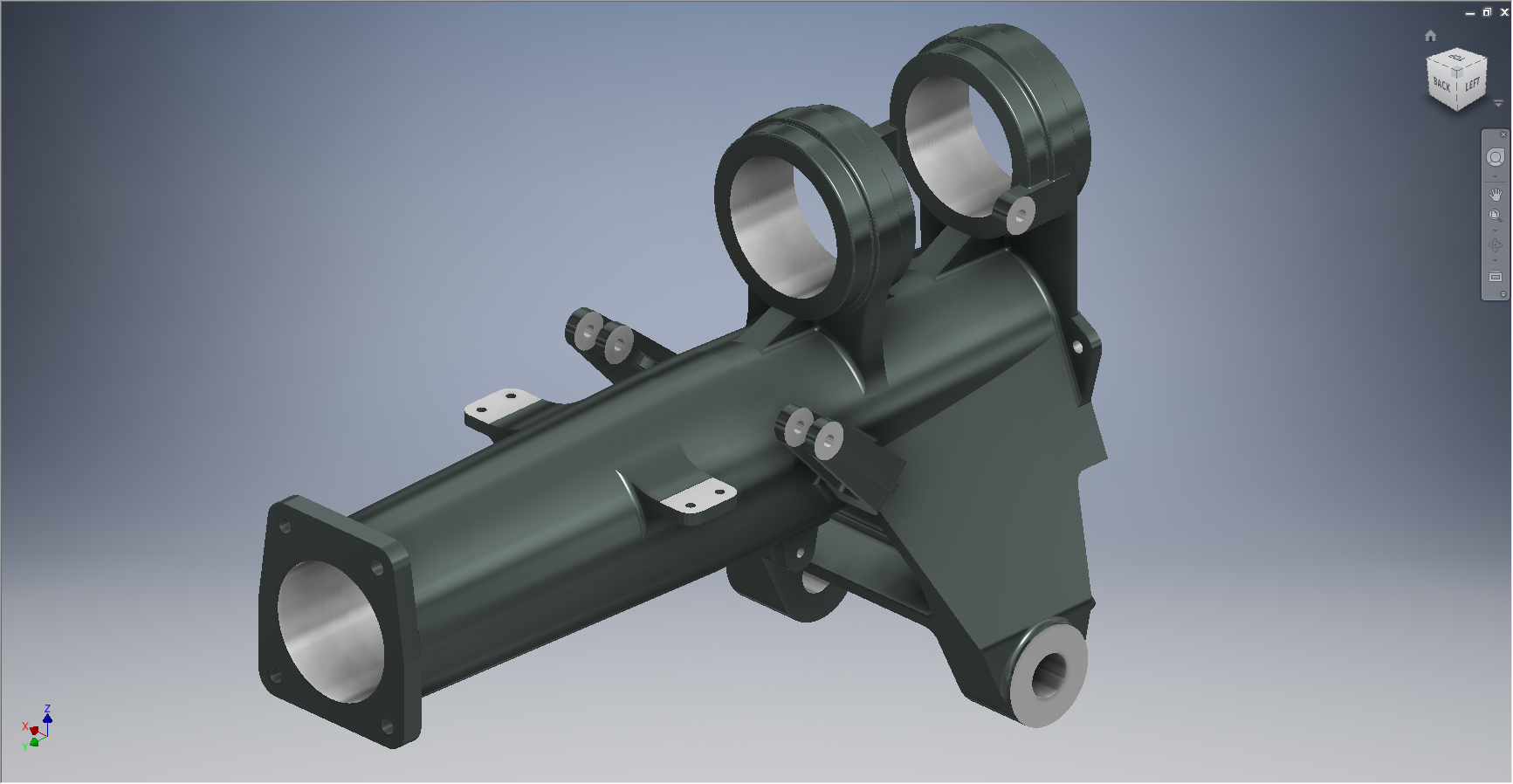
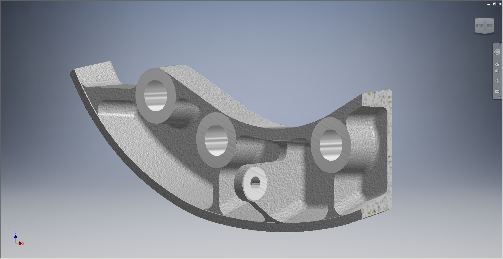
The machining model is a separate Cad part file created from NAA drawing #73-34161 which has the casting body and sketches derived from the first Cad model above. I can now go about working on the derived model; creating the machined elements and holes; without affecting the original model file above as shown.
The great thing about working this way is that should the original casting model change then this will be propagated to any other cad part files to which this item is derived but conversely any changes in these Cad part files are not reflected in the casting model.
I still have a few minor details to finish this model but thought it may be prudent to touch on the derived part capabilities of the Inventor product.
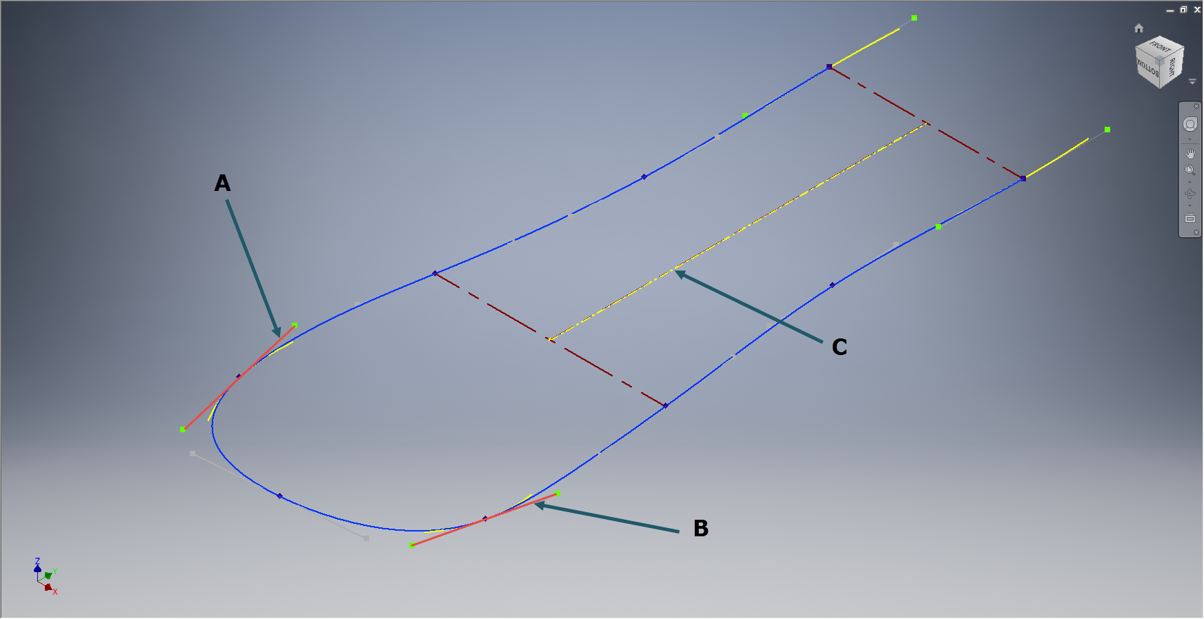
Another use for derived components is when you only have Inventor LT (Lite version) which is a parts only product and unlike its big brother does not handle assemblies. Using the derived feature it is possible to create a proxy assembly for checking the alignment of parts as shown below.


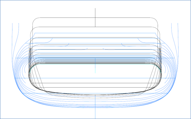
This is the armor plating for the Mustang P-51 Firewall; with the top section modeled separately from the bottom section. In this example, I have derived the top part into the lower part file as a surface model to assess the alignment and curvature continuity.


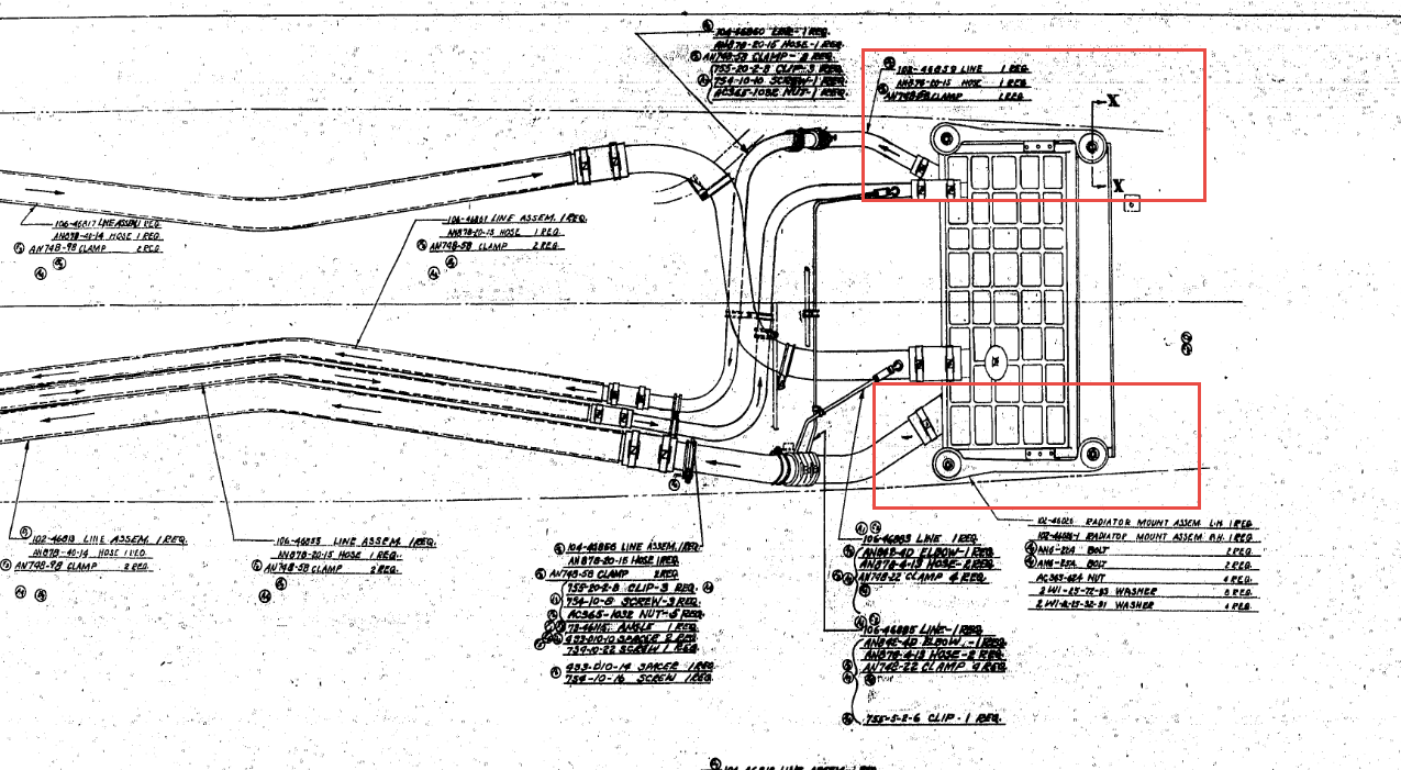


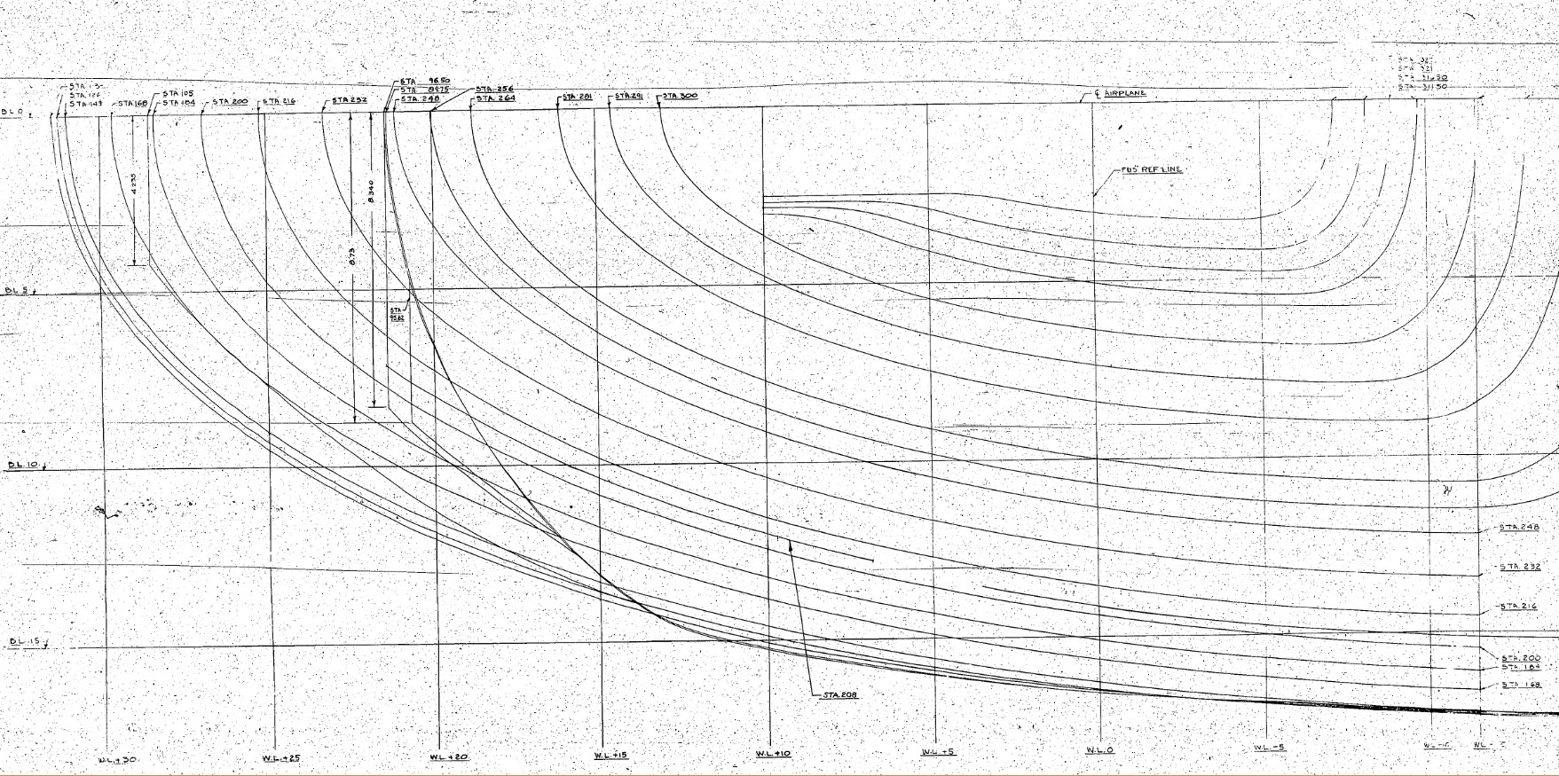


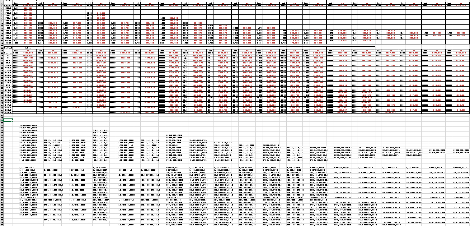
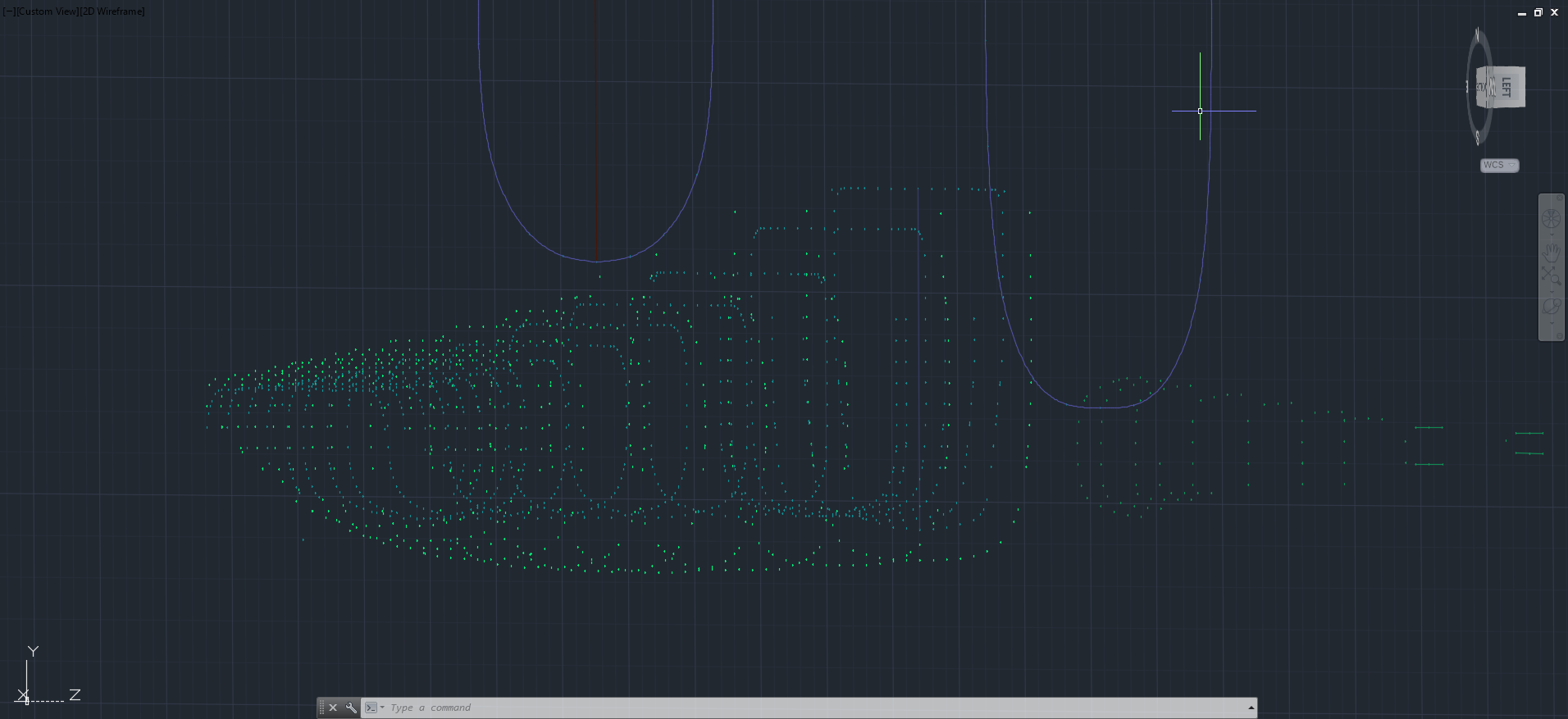
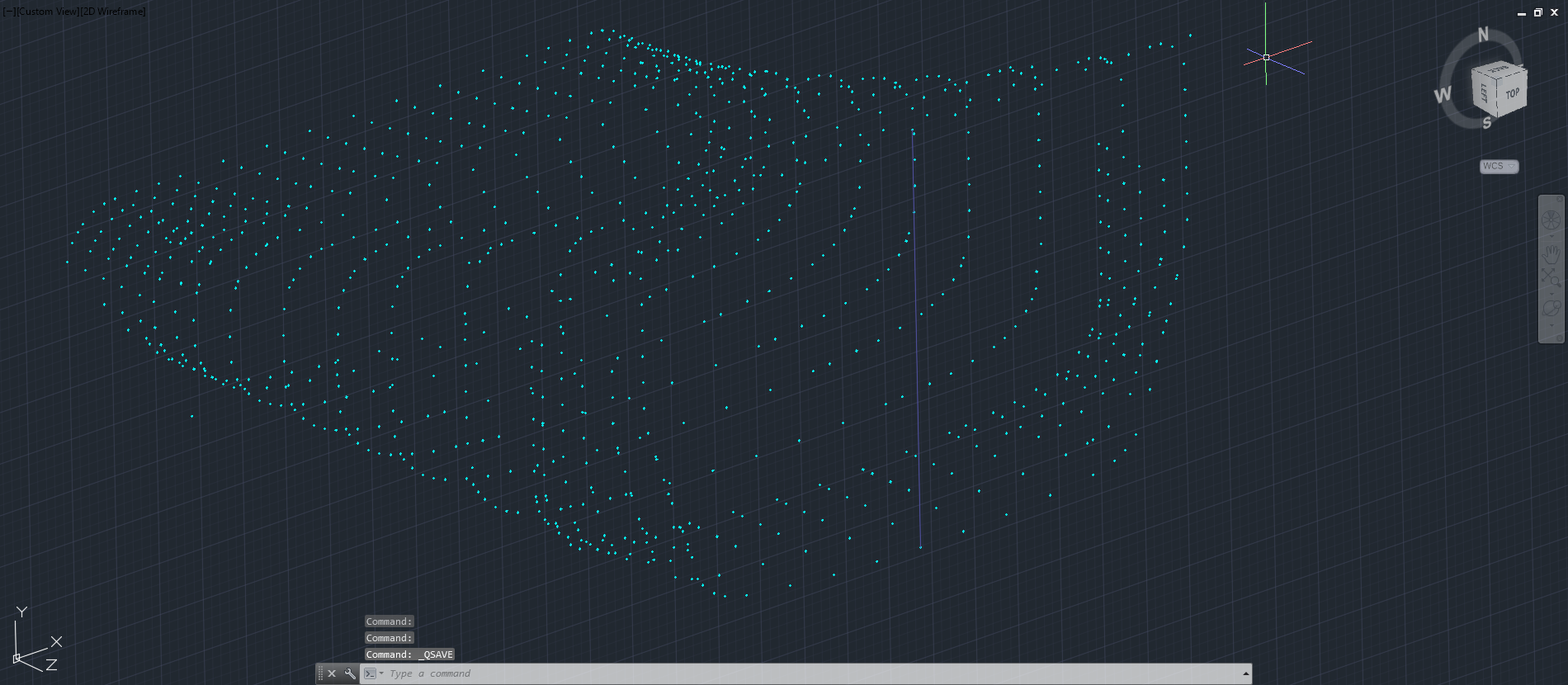
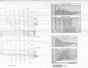 This is a scrap view of the original NAA drawings showing the main ordinates for the Air Scoop.