Hoppers: Surface Modelling for Mass Containment:
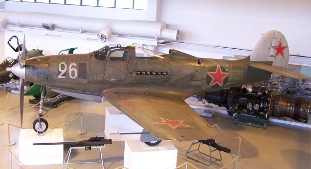
Although not directly associated with aircraft design there are inherent modelling techniques equally applicable to many aspects of aviation. The techniques relate to surface modelling for the containment of a known mass or volume. In each case, the criterion is the specified volume or mass that ultimately defines the size and shape of the container.
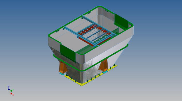
This particular hopper is for a Transfer car used to feed Steel Plant Coke Ovens with coal. The development of this hopper combines surface and solid objects in a single multi-part model that is configurable via a dialogue populated wth the key parameters. Surface modelling can be used for various purposes; some of which I have covered in previous articles for the creation of sheet metal flanges, trimming solids and providing a boundary for extrusion or as a containment for a solid component; as I have used here.

This type of hopper is fed from an overhead bunker and releases the fill material through an aperture in the base. The mass volume is modelled according to industry specifications that define the slope of the poured coal defined by the size of the top bunker opening.
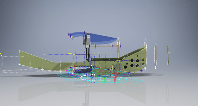
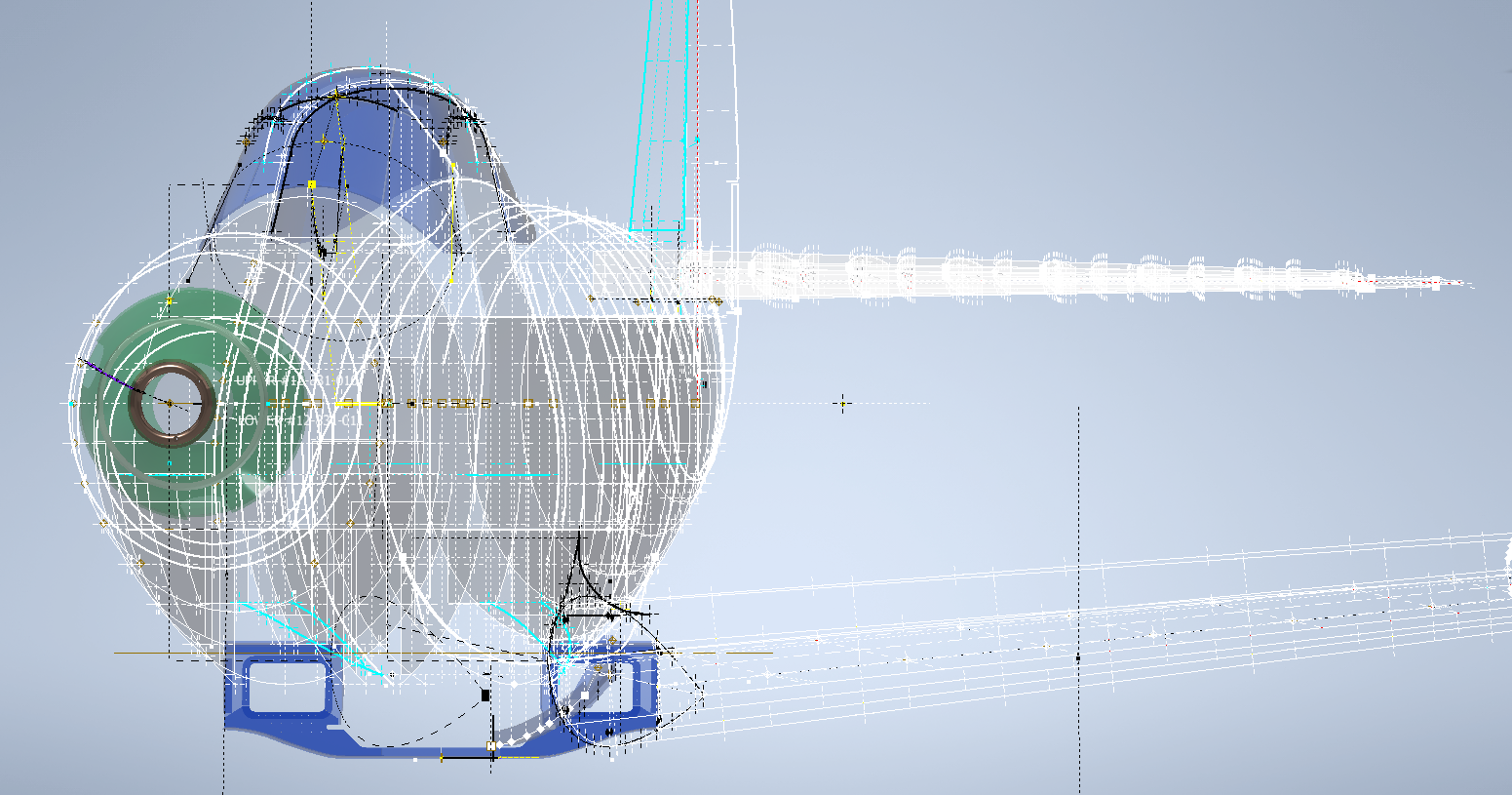
The surface represents the containment boundary which has zero volume and zero mass therefore by definition will ensure that the only properties recorded for mass and volume in the 3d model relate only to the fill material. The image above shows some of the key parameters used to model this hopper as a part file with an ilogic form to make it easier to adjust the parameters to suit the project design.

The gray values for the Coal Volume and the Centre of Gravity are the results calculated from the physical dimensions of the coal mass and the containing surface model. Once the correct dimensional and mass properties are determined the surface objects are extrapolated using the “Make Component” command in Inventor which creates a separate derived part file and also (optional) includes the part file in an assembly placed at the original coordinates. In the surface part file we simply thicken the surface to generate the solid plate material that will form the structural body of the finished hopper.

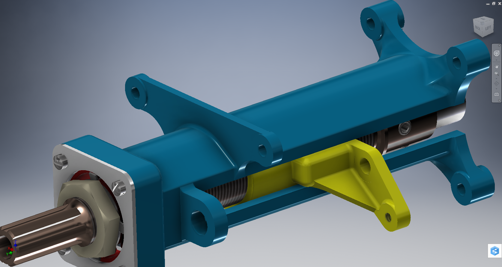
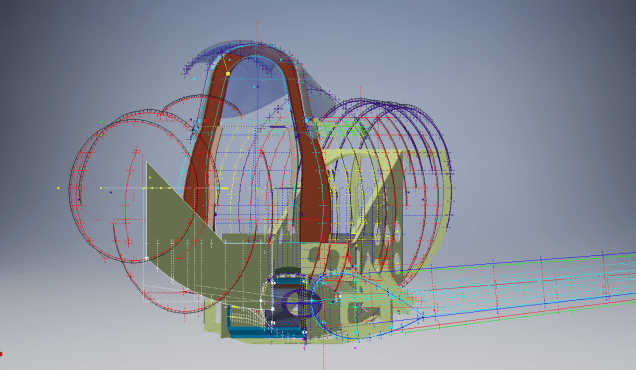
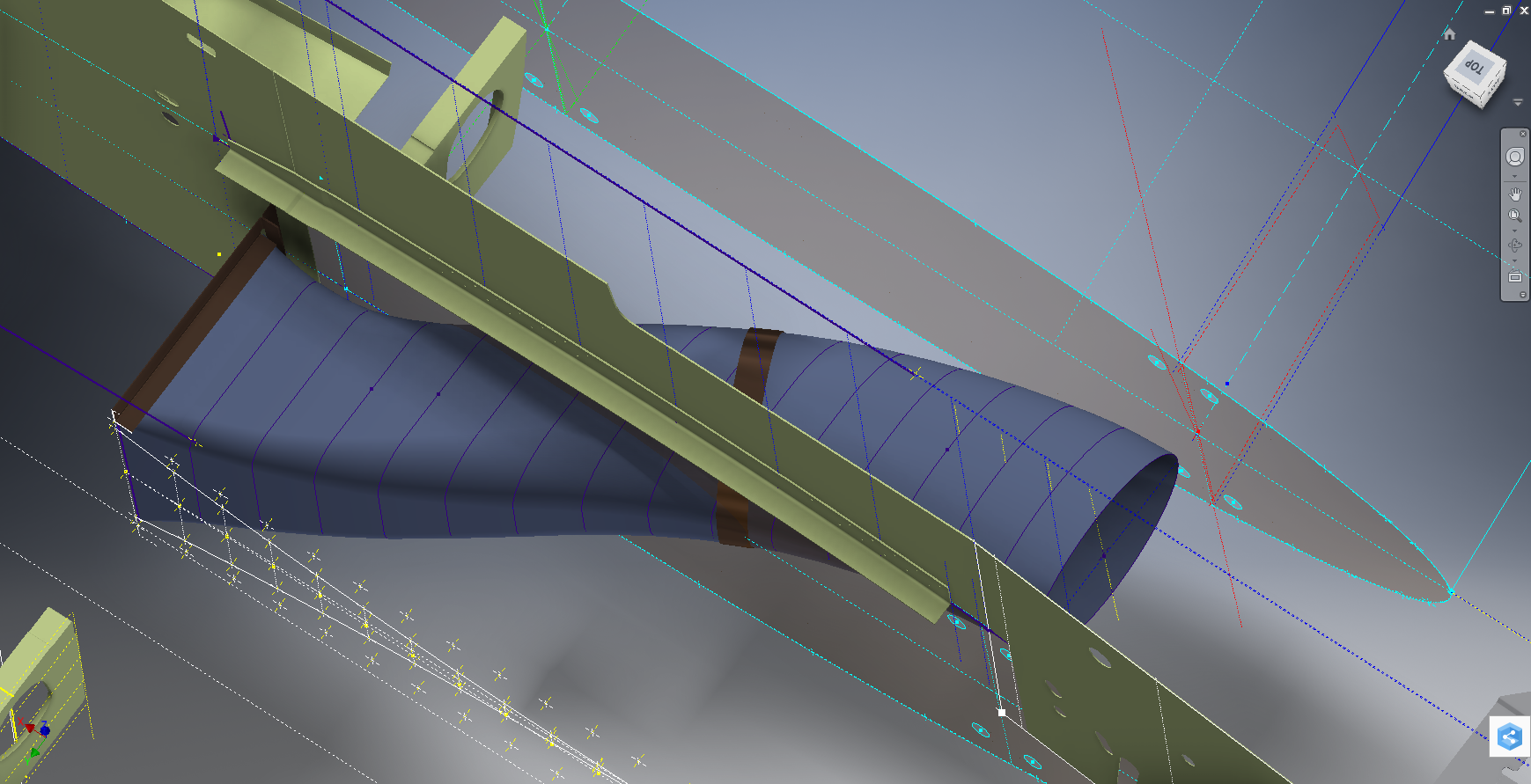
This is a very basic introduction to using surfaces where the mass or volume of a fill material is the critical component. On some forums, similar questions have been asked for complete hoppers where programmed solutions are offered to subtract all the structural objects to derive the fill mass and volume. By using surfaces with zero mass and volume to contain the fill there is no need for any programming solutions. There are a few ilogic basic routines included in this example for formula calculations and shifting the location of the bunker output. Another example just for reference is the casing for a screwfeeder:

Surfaces are extraordinarily versatile with many applications, only some of which have been mentioned in this blog. For this example, we could extend the technique to modelling fuel tanks, hydraulics and oil tanks where the volume and mass are critical.


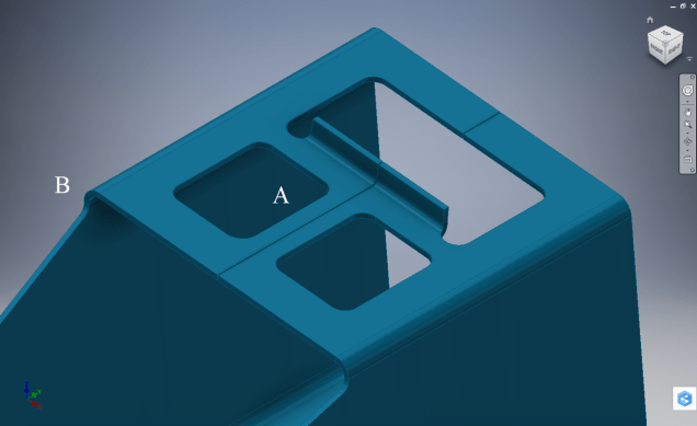


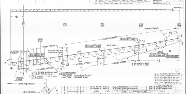
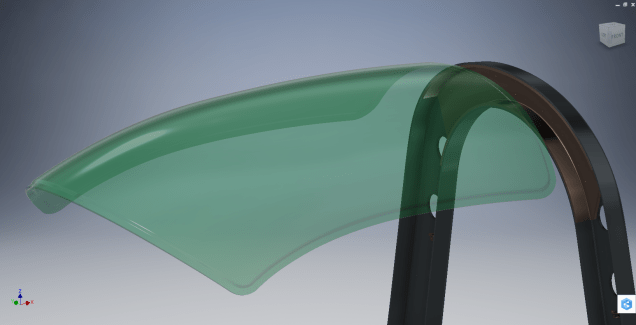


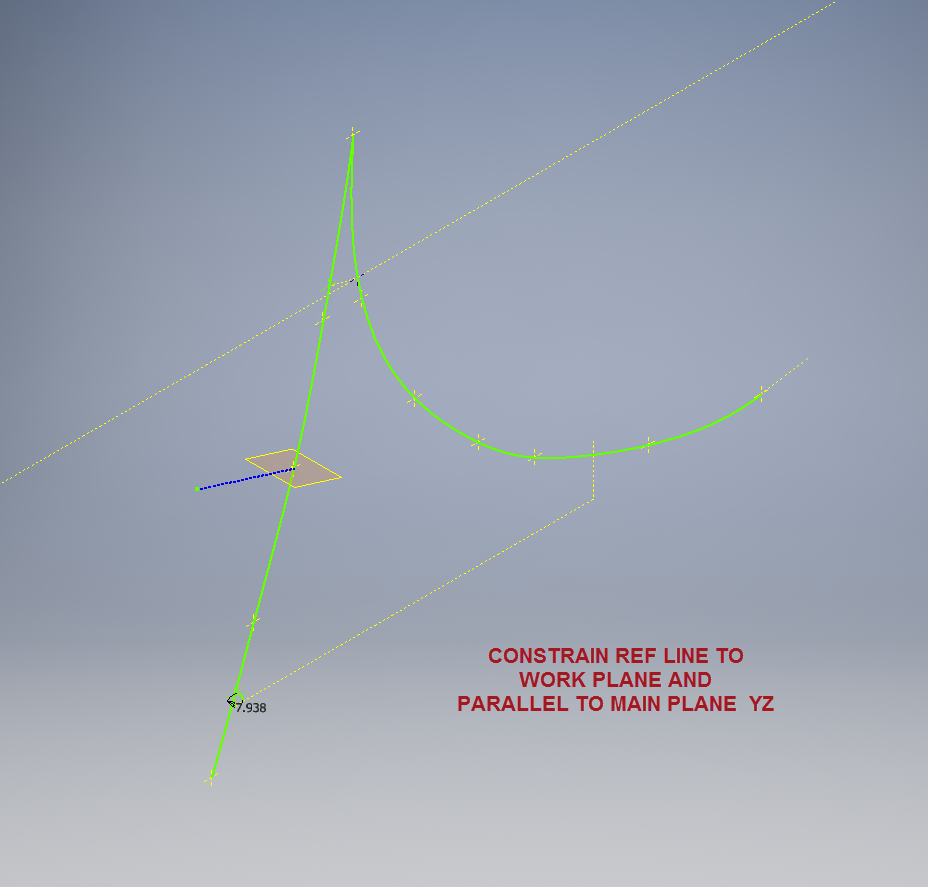
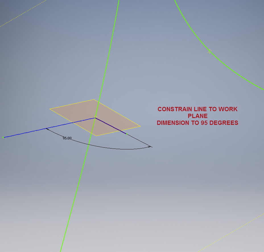


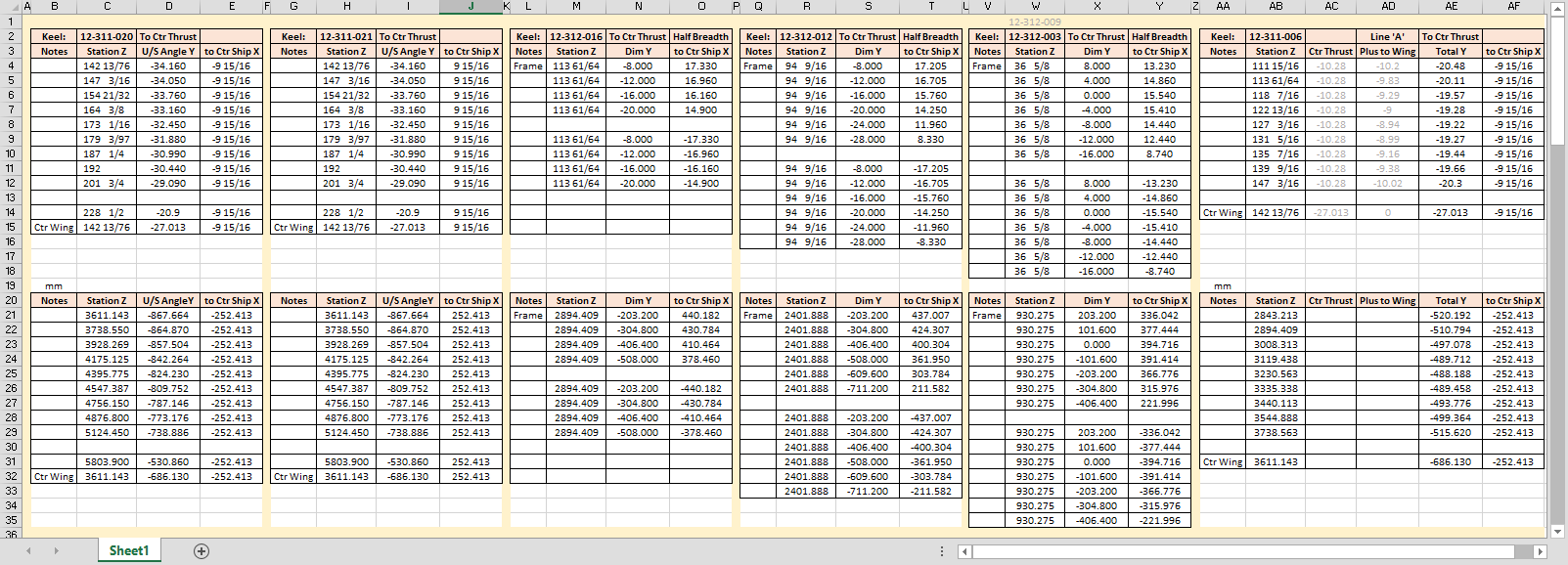
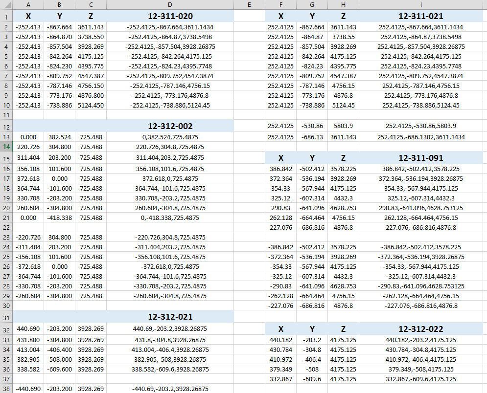
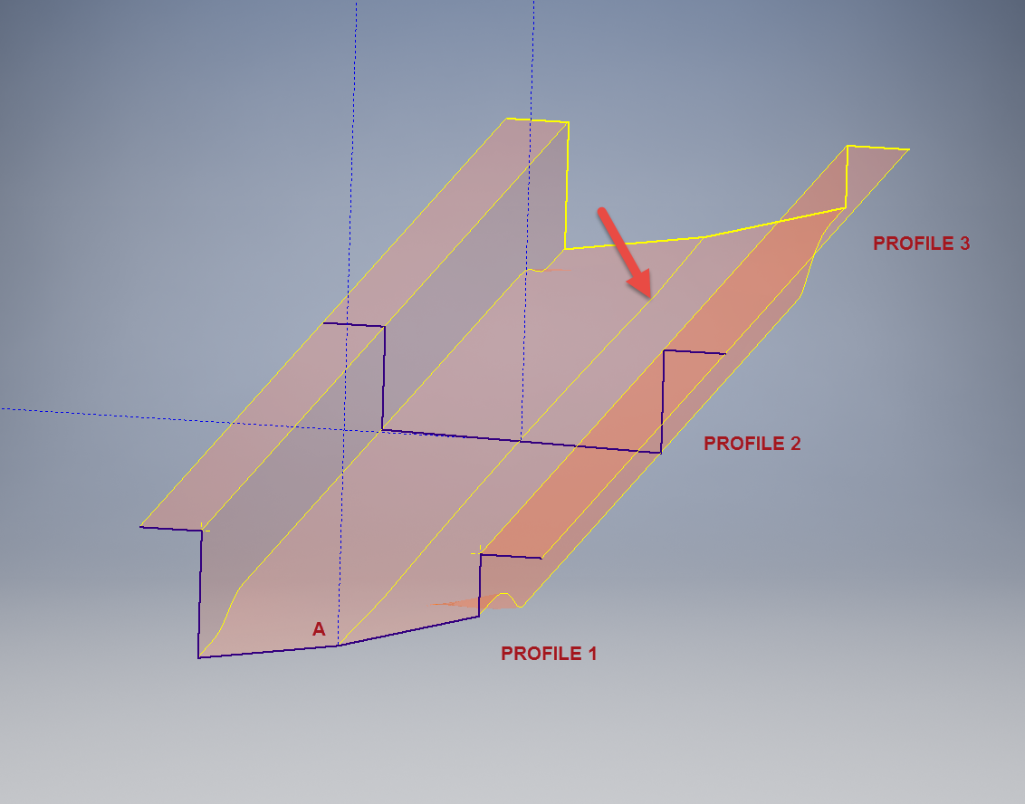 This is the lower level fuselage cross member that has a built in twist to align with the connecting frames at both ends. The model consists of 3 profiles with the 2 outer ones containing a small angular deviation in the centre at point A. Normally I would loft the profiles to create the finished surface but this projects the deviation throughout the length giving us 2 surfaces; which does not look good.