Technote: Scaling Ordinates:
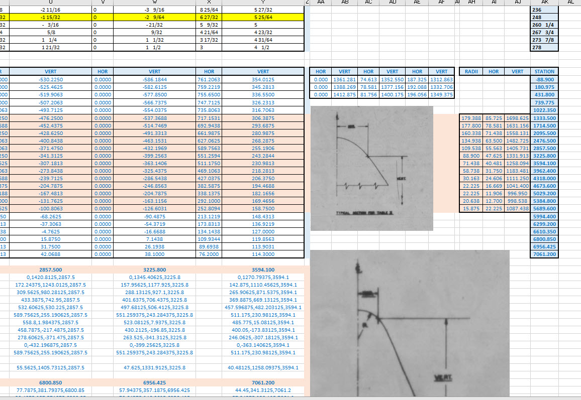
The primary objective of my work is to record an accurate database of ordinate dimensional data for various aircraft fuselage frames, cowls, wings, cockpit, and stabilizers. This database is derived from manufacturers original documents and drawings.
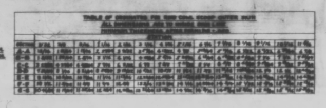
Often the original source documents are poor quality, occasionally almost illegible, but if we have 95% of the ordinates for a frame then it is relatively straightforward using today’s technologies to determining the missing 5%. Where possible I will cross-reference with part drawings or alternative information to verify.
However, most archive records are incomplete, as was my frustration with the F6F Hellcat. Having completed the wings, fuselage, and cowl I was stumped by the apparent lack of ordinate data for the tail and horizontal stabilizers (even from part drawings).
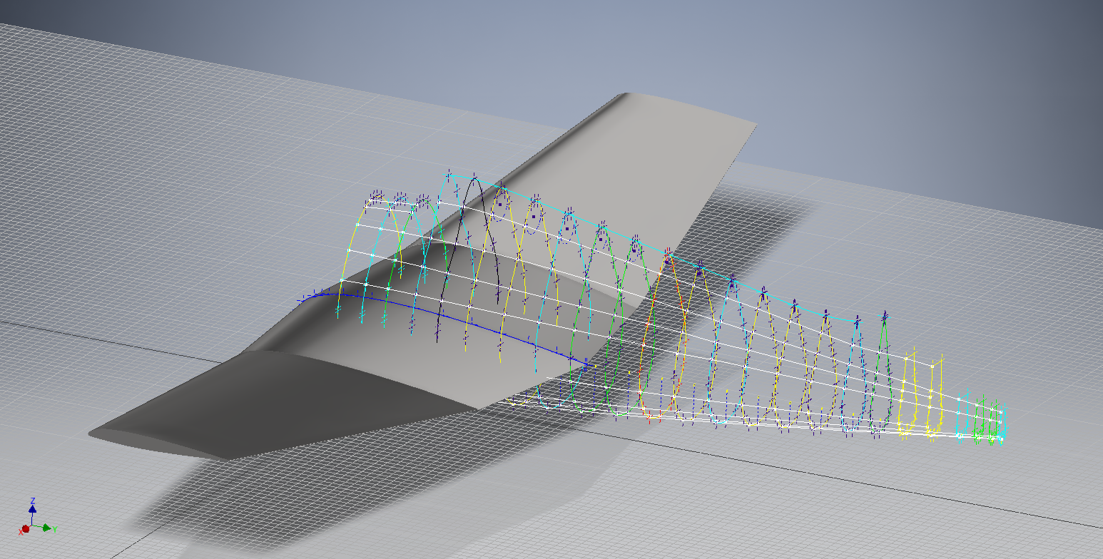
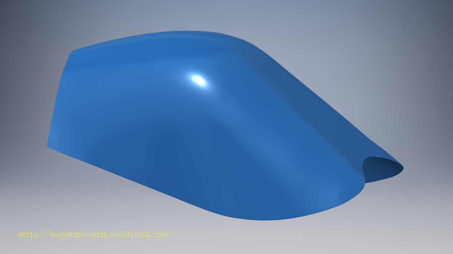
There are 2 approaches to determining the missing information. The first is to model the information you do know; from part files, supporting documentation and 3rd part resources. This may provide enough information to determine the missing geometry in order to extrapolate a dimensional data set.
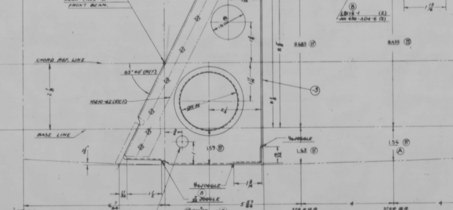
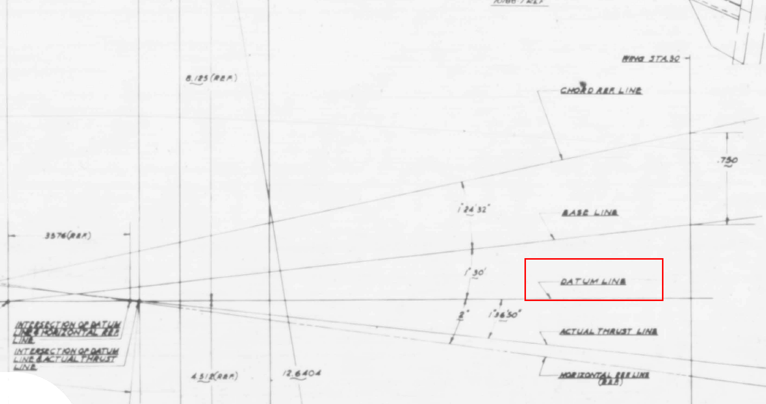
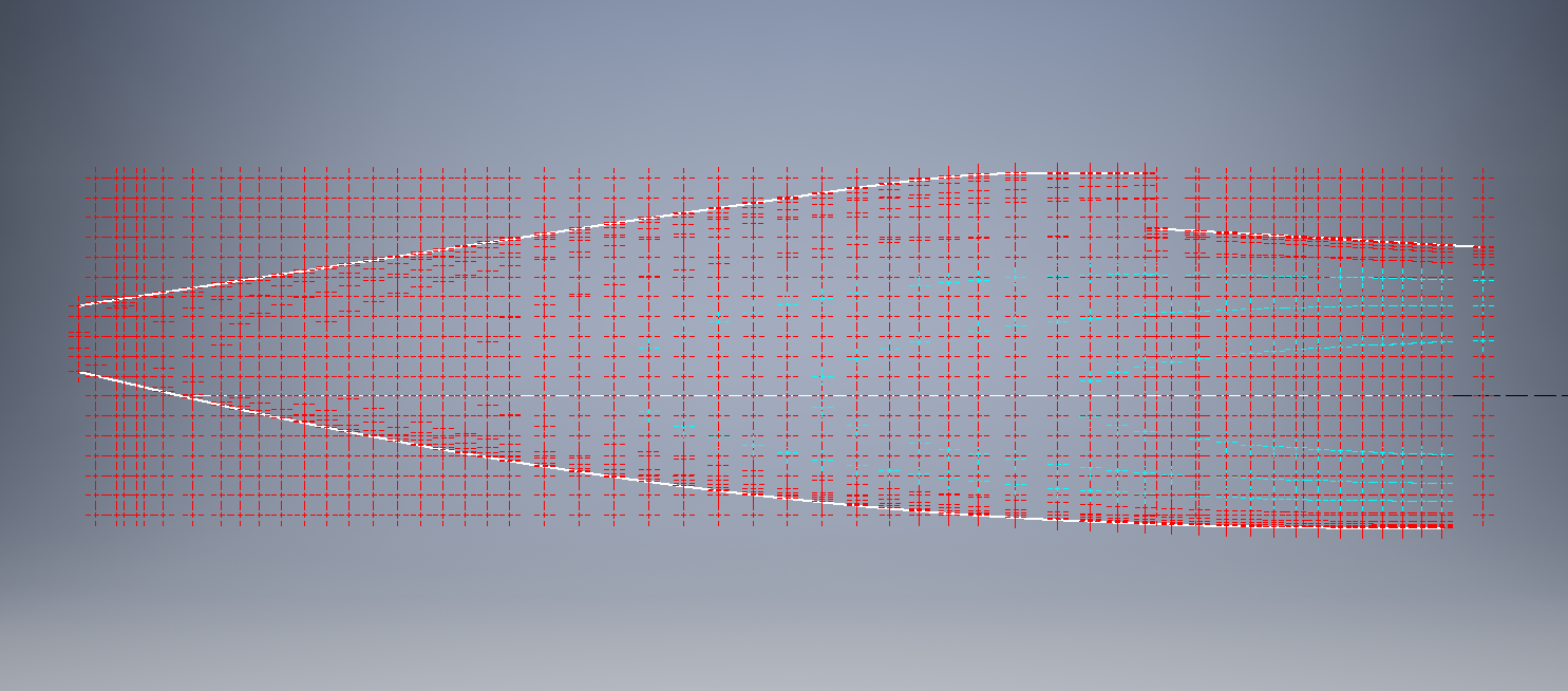
The second; and I would never do this myself; is to trace or convert the outlines of the components from the scanned drawings. There are several products available that will convert raster images to vector files but first, we must achieve a properly scaled image to work with. Most raster image from these archives are scans from 35mm microfilm and due to the nature of the process, the resulting image will not be equally scalable in both X and Y directions.

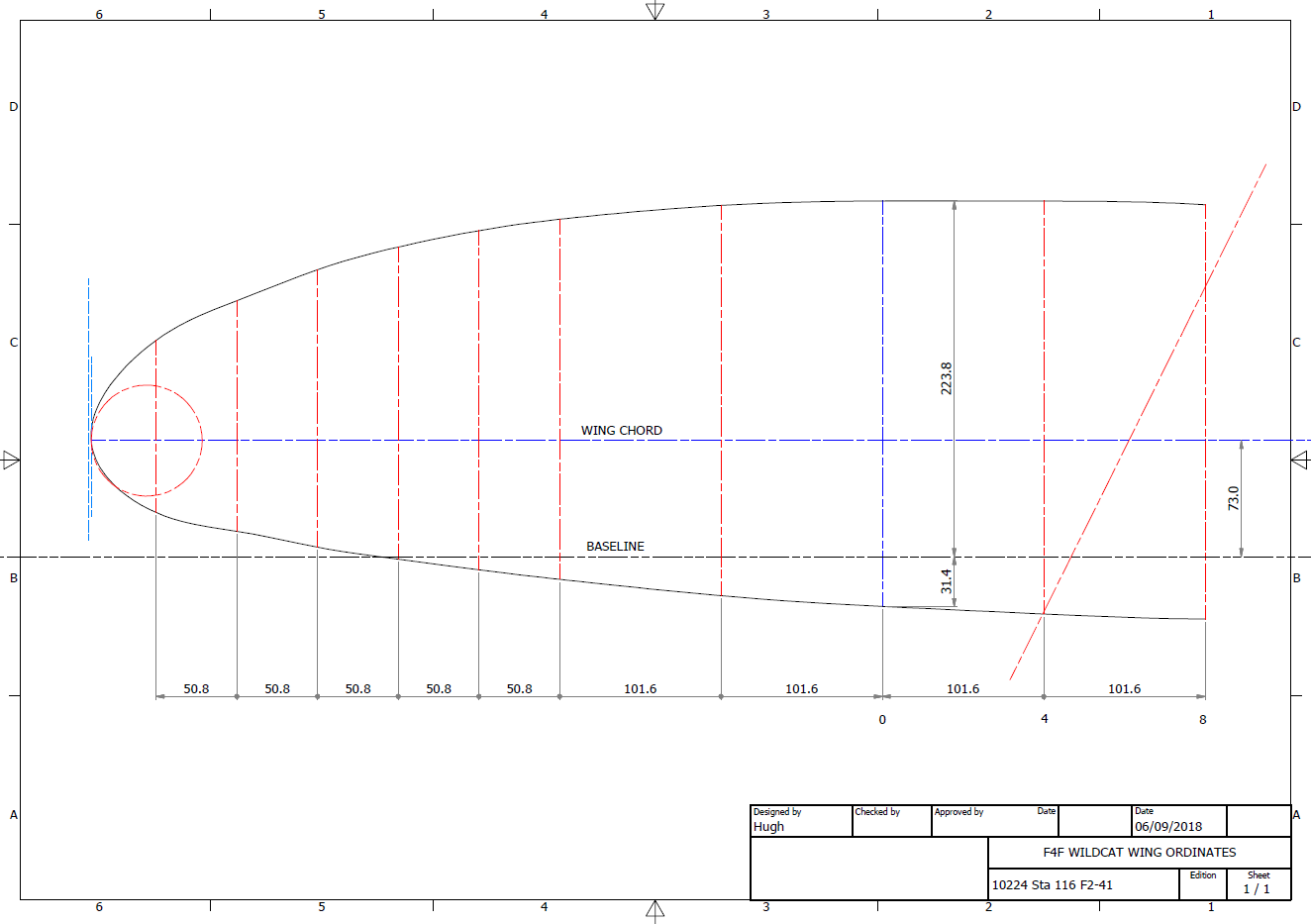
Assuming you wish to work with CAD and use this image as a background I would recommend the following process to achieve the best result. This particular drawing is created from actual loft templates and includes the locating pins set to a specified distance in each of the corners plus a drawing scale rule.
Some drawings may only have scale rules, either way, the process is the same.
If we insert this image directly into a drawing in Autocad or similar the only option is a user-defined global scale parameter which will scale the image equally in both X and Y directions, which is not what we want. Even once the image is inserted the option is the same.
The best way to circumvent this is to insert the image into a drawing, without any scale parameters applied. Then save this drawing including the image as a DWG file.
Xref this drawing into another drawing and you will be presented with the following dialogue box ( I am using Draftsight but Autocad will be similar).

As you can see you now have the option to apply different scales to the X and Y directions. This works very well and will provide a very good reference for your work. I should clarify that some CAD products have the option to insert an image as an Xref but the scaling options are not the same as for a DWG file, instead reverts to a global scale option only.
As a workaround for missing information, this is a very accurate way of achieving a good result and will satisfy the majority of applications.
As my projects are records of known dimensional information this process would not be applicable.


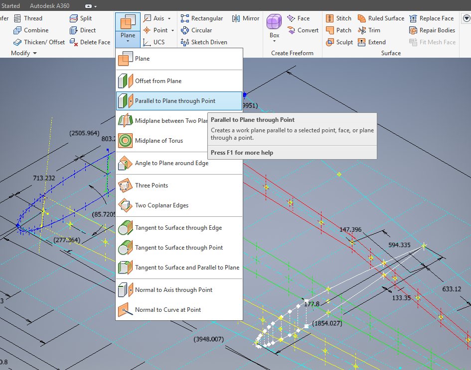
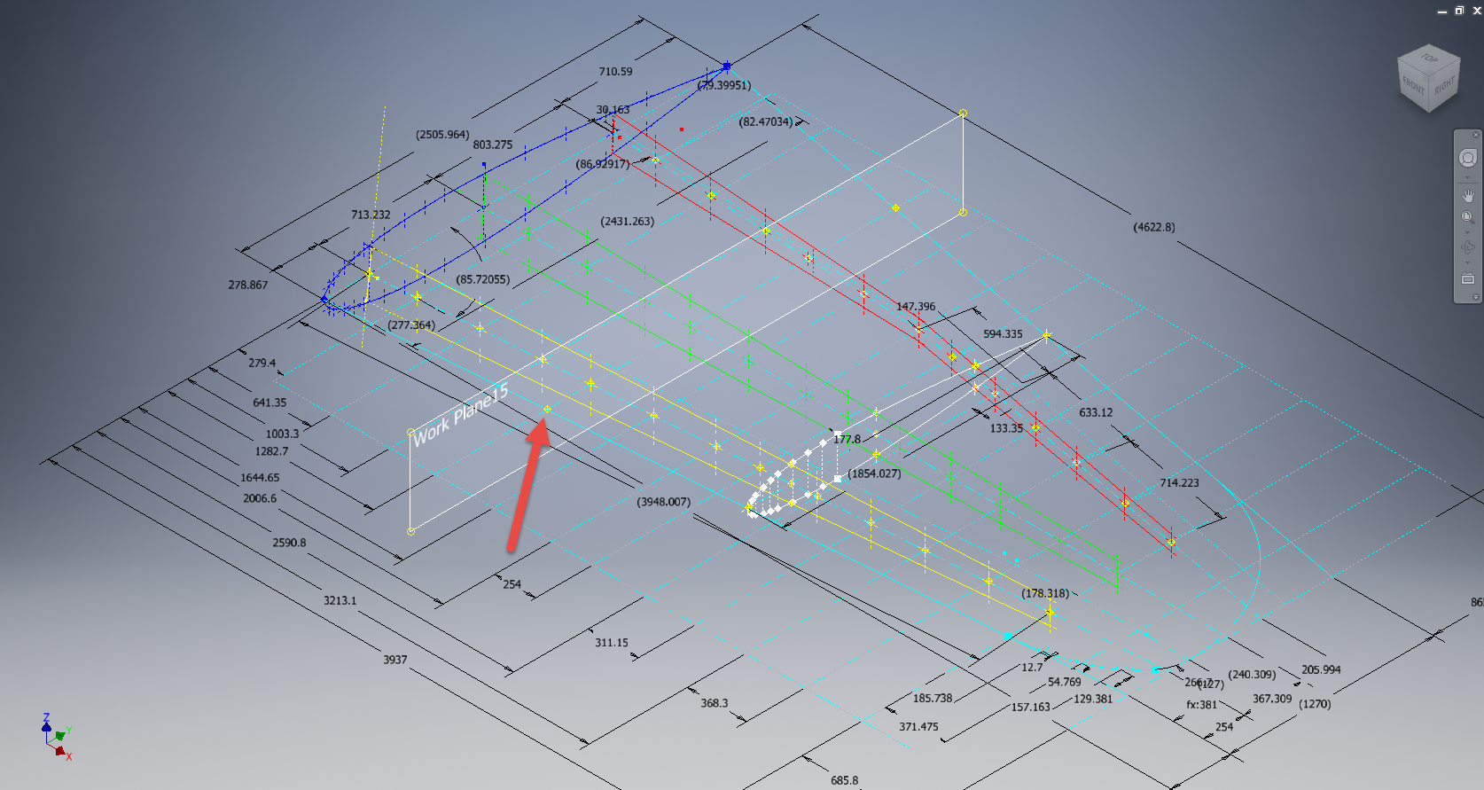
 The technique I used is described in this video on


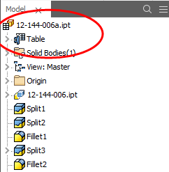 This creates a Table which appears in the model browser. It is usually a good idea to give parameters meaningful names as I have done here for the Length, Width and Height.