Technote: Spherical Wind Turbine (Updated 2nd April)
You probably realise by now that outside of Aviation, I have an interest in many types of engineering projects from HiFi Audio systems to wind turbine design.
I am captivated by the numerous projects created by the extraordinary Robert Murray-Smith, which are showcased in his many YouTube videos. Unfortunately, Robert is no longer with us, and his passing is a great loss to the community. Rest in peace.
One of his videos featuring the O-Wind Spherical turbine sparked my interest, and the latest version inspired me to explore how spherical wind turbines could be developed in CAD. Link to Roberts video: O-Wind Turbine
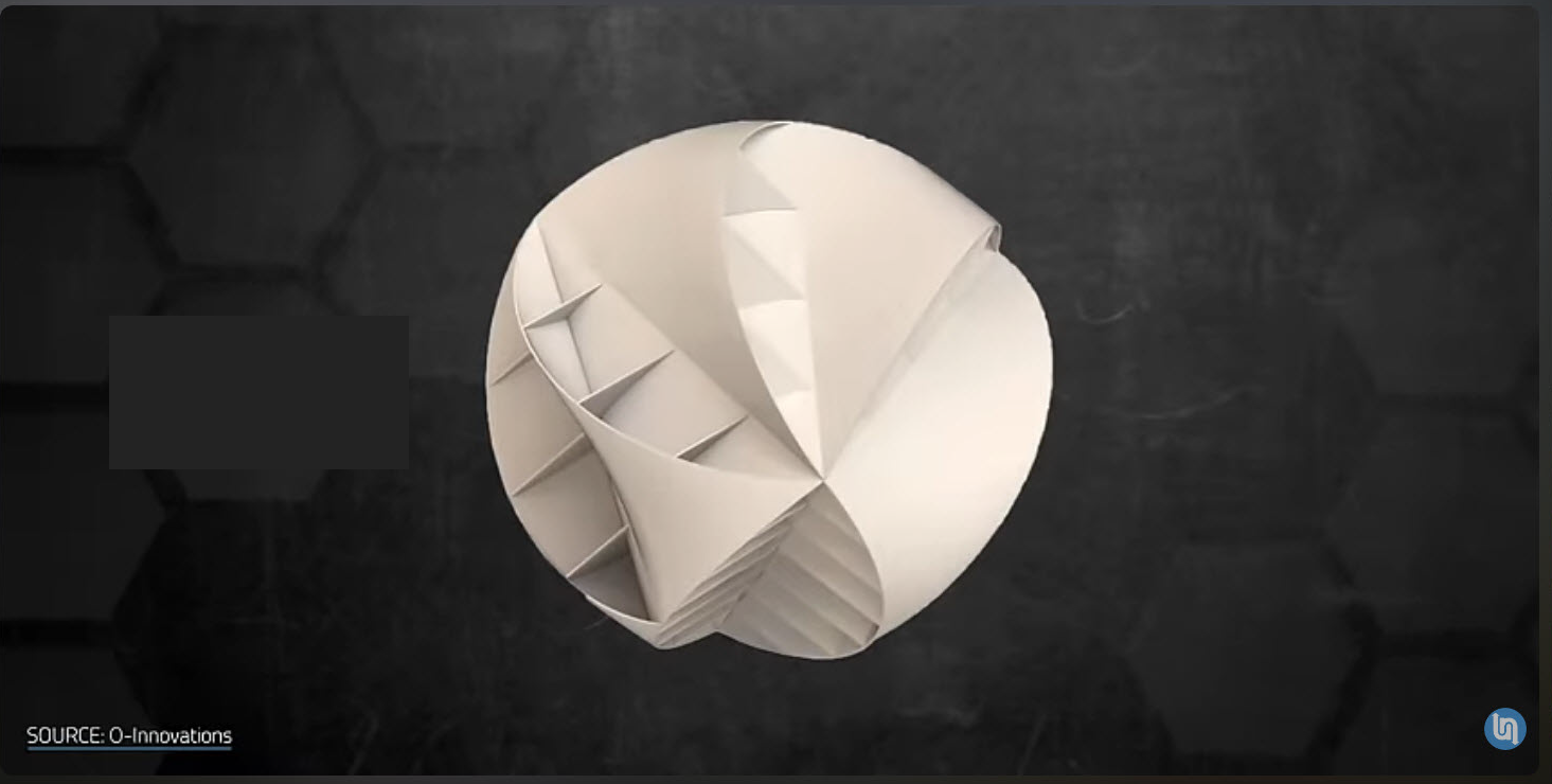
This screenshot features the latest O-Wind Turbine, which is designed for omnidirectional operation. This means it can capture wind from any direction, making it particularly suitable for urban environments. While the design is visually appealing, I share Robert’s curiosity about why it appears that the ducts are closed.
You might also be curious about the vertical slats seen along the bottom faces. I believe their purpose is to house the generator components within the sphere. Additionally, these slats may help with cooling and provide structural integrity.
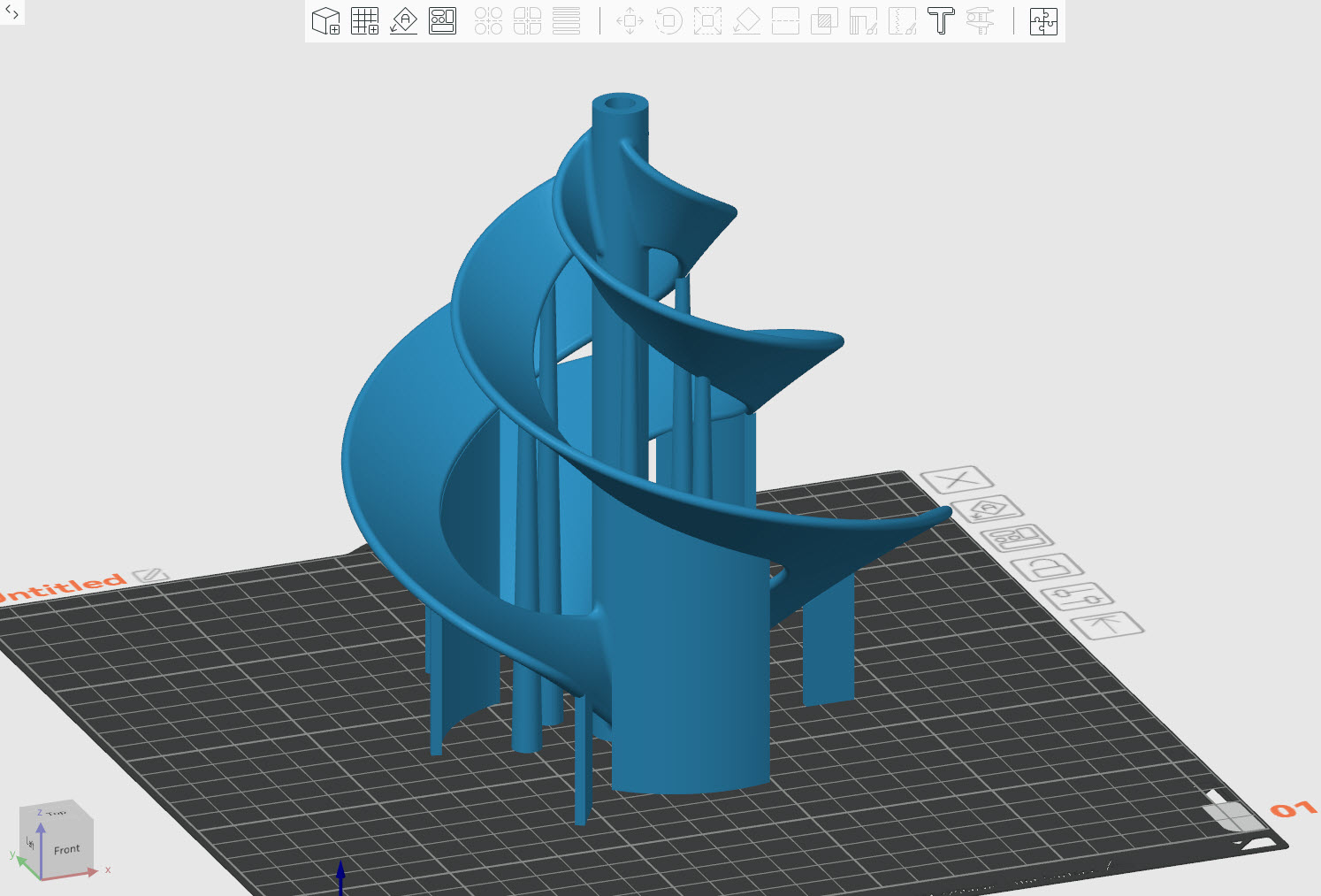
Here’s my take on a spherical wind turbine!
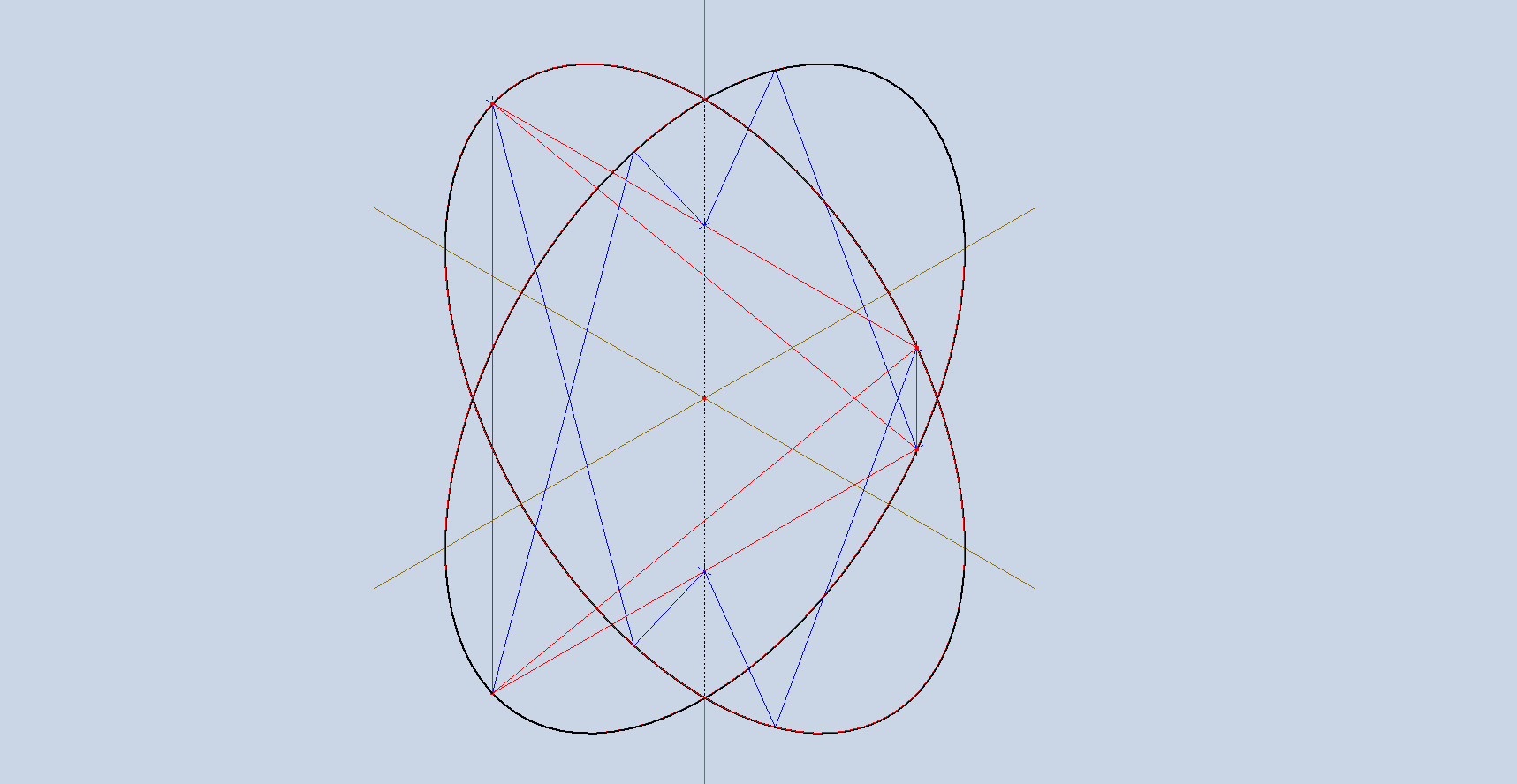
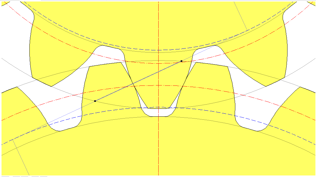
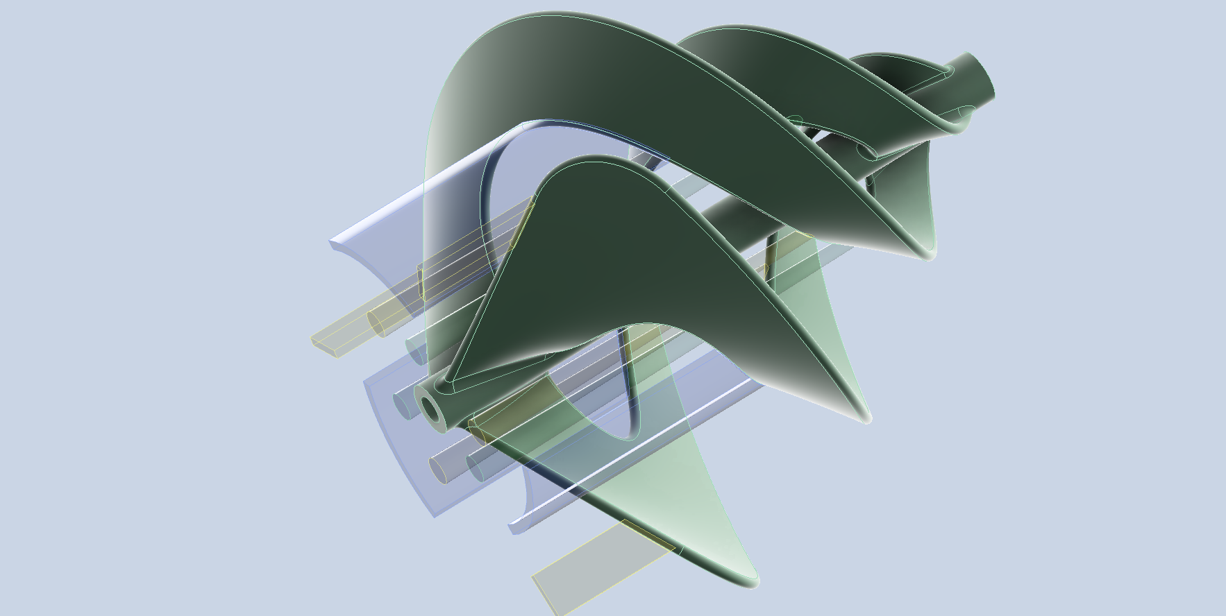
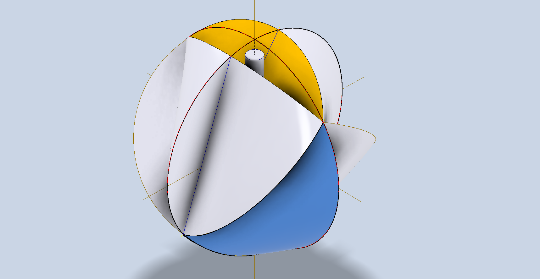
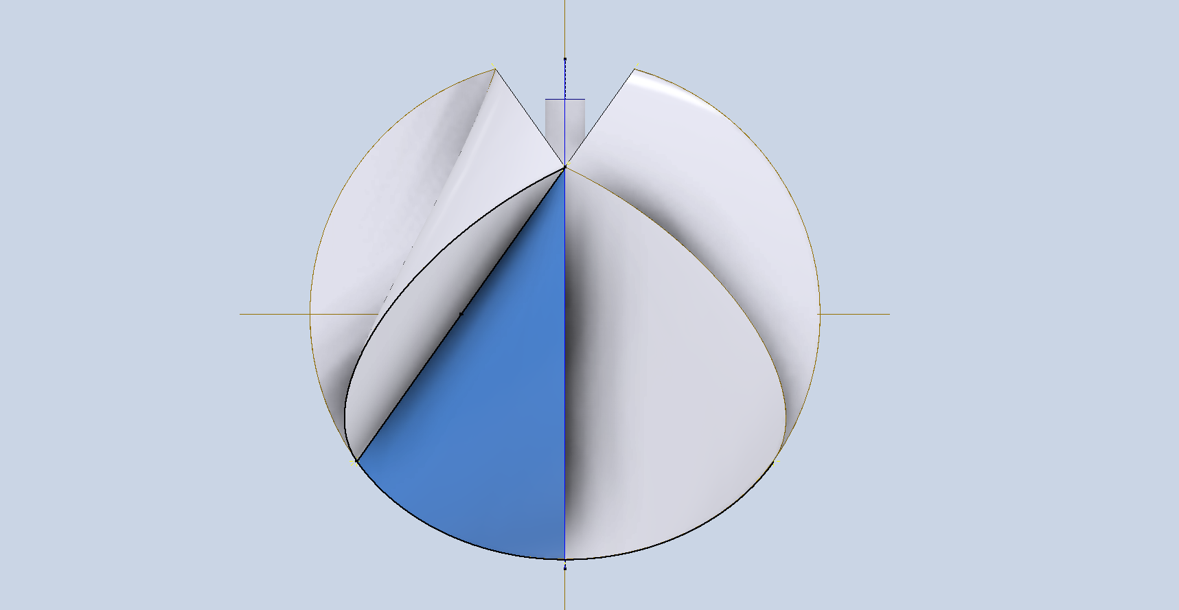
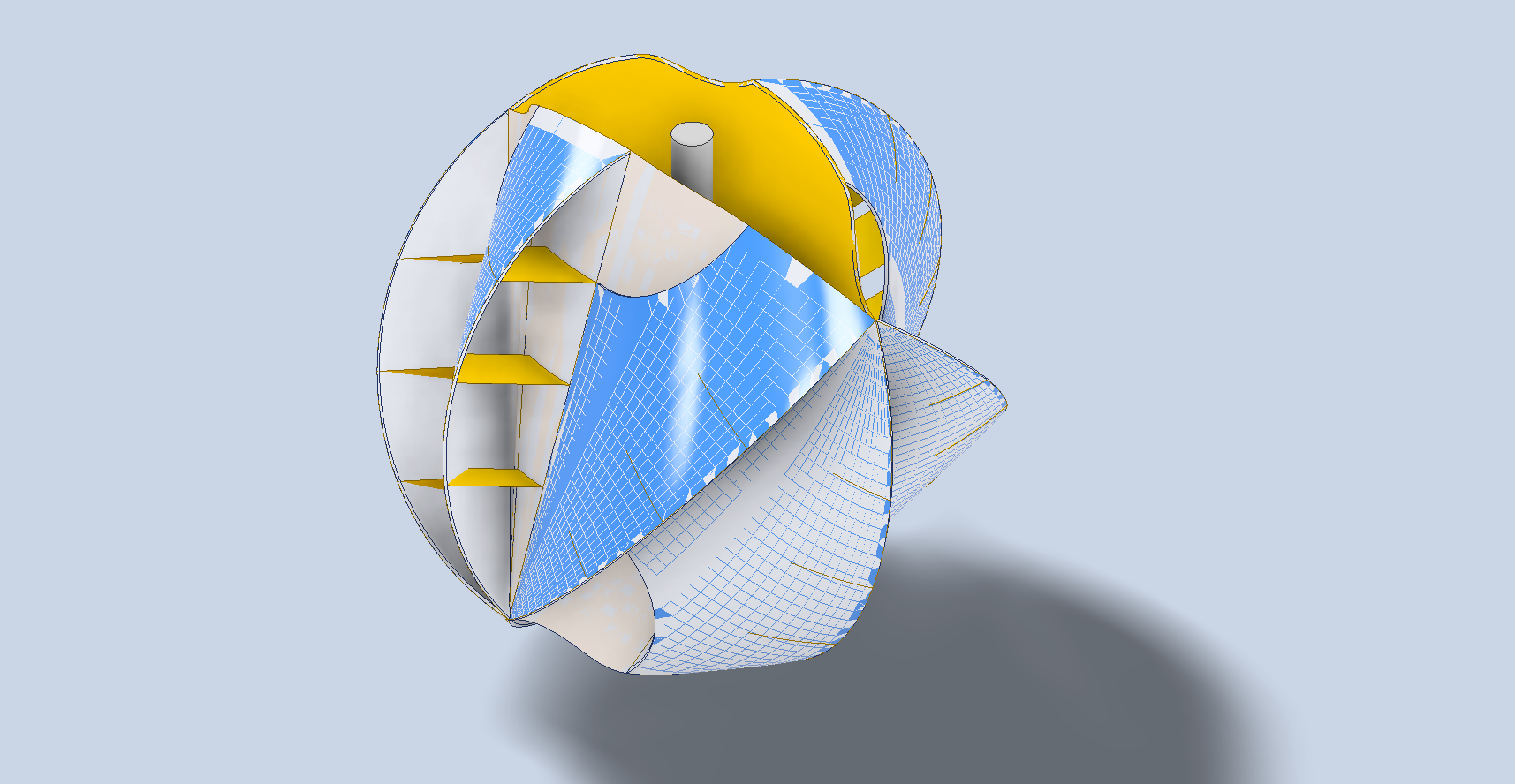
You start with 2 circles of equal diameter perpendicular to each other as shown. Within the circles, we can construct a trapezoidal type form where all the red lines are of equal length. The Blue lines are for the first 4 ducts, where the length of the longest blue line is equal to the trapezoid red lines. The duct surfaces are shown in the second image.
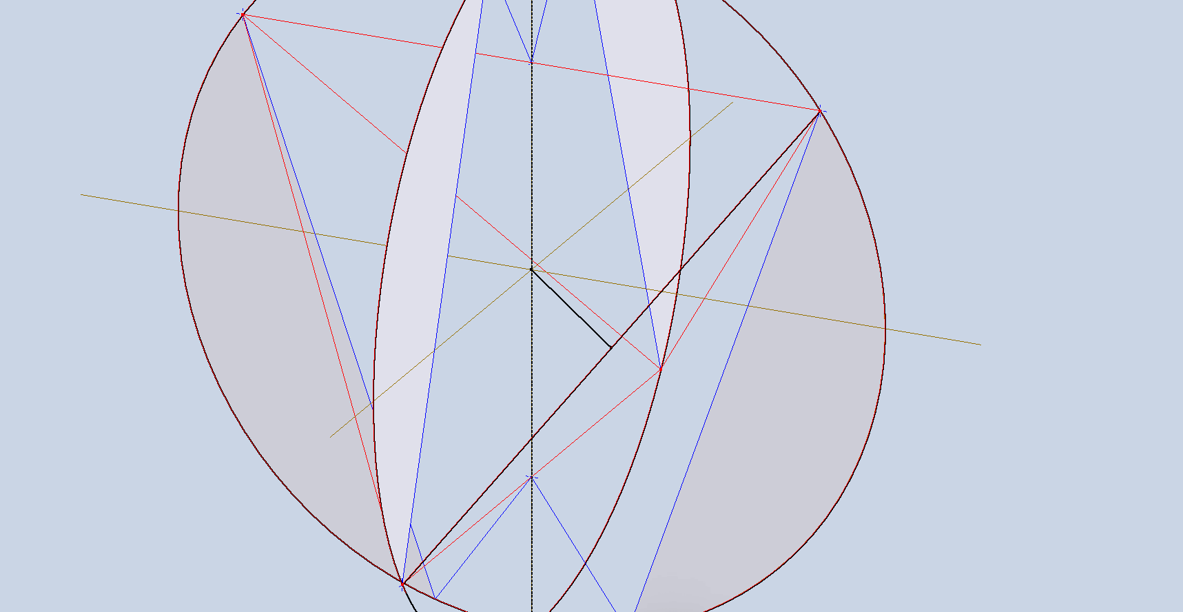
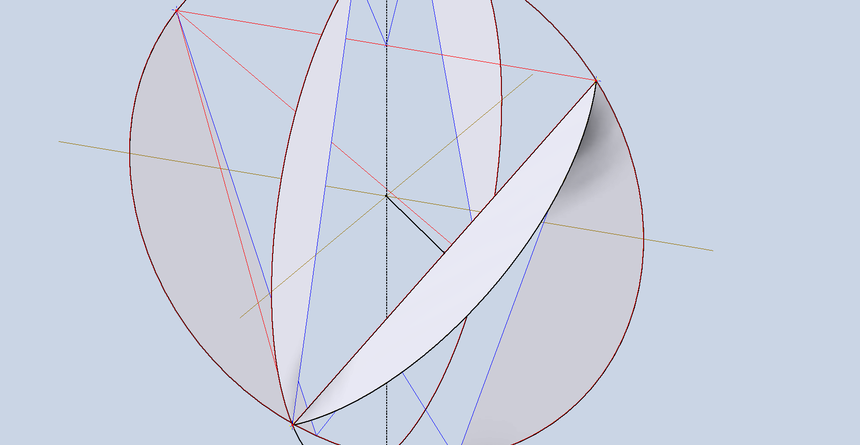
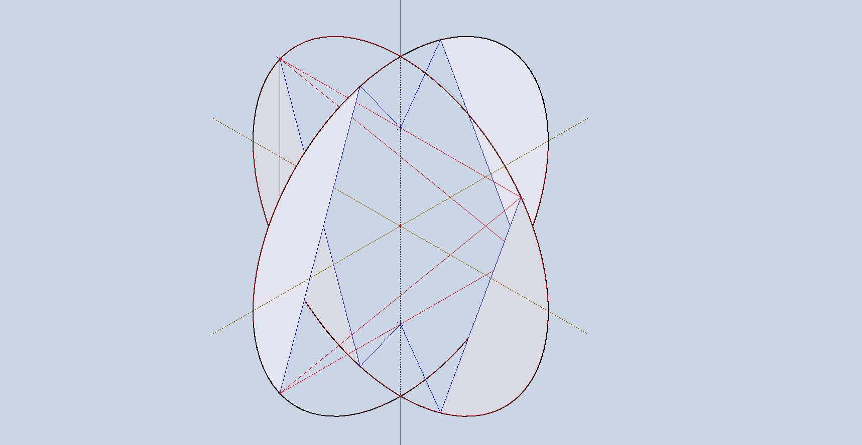
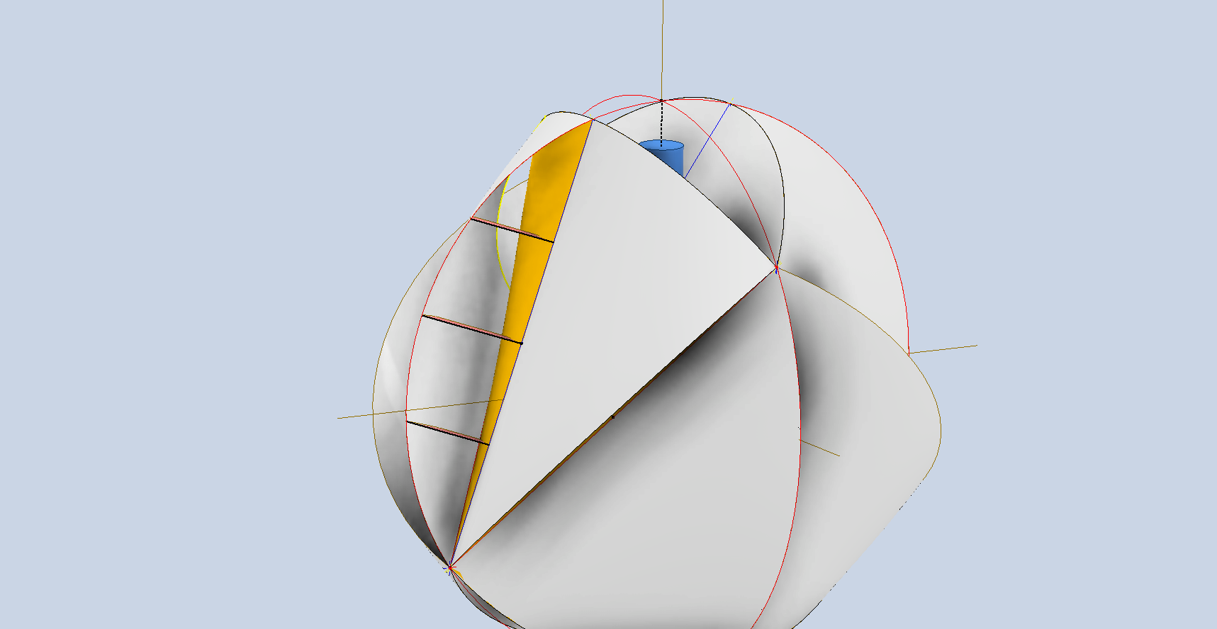
The remaining 4 ducts are located on the trapezoid diagonal lines. The eventual surface must be correctly aligned with the main vertical axis; to do this, we construct a 3D line that intersects the main vertical Z-axis and is perpendicular to the sloped red line. Check that the 3D line intersection with the axis is coincident with the circle datum point. I would normally just create a plane from the datum point and select the 2 end points of the red line, but I felt it was important to describe the intent. In the second image, you can see the duct’s planar surface that is perpendicular to the axis of rotation.
Mirror that surface across both vertical planes to complete the development of the ducts.
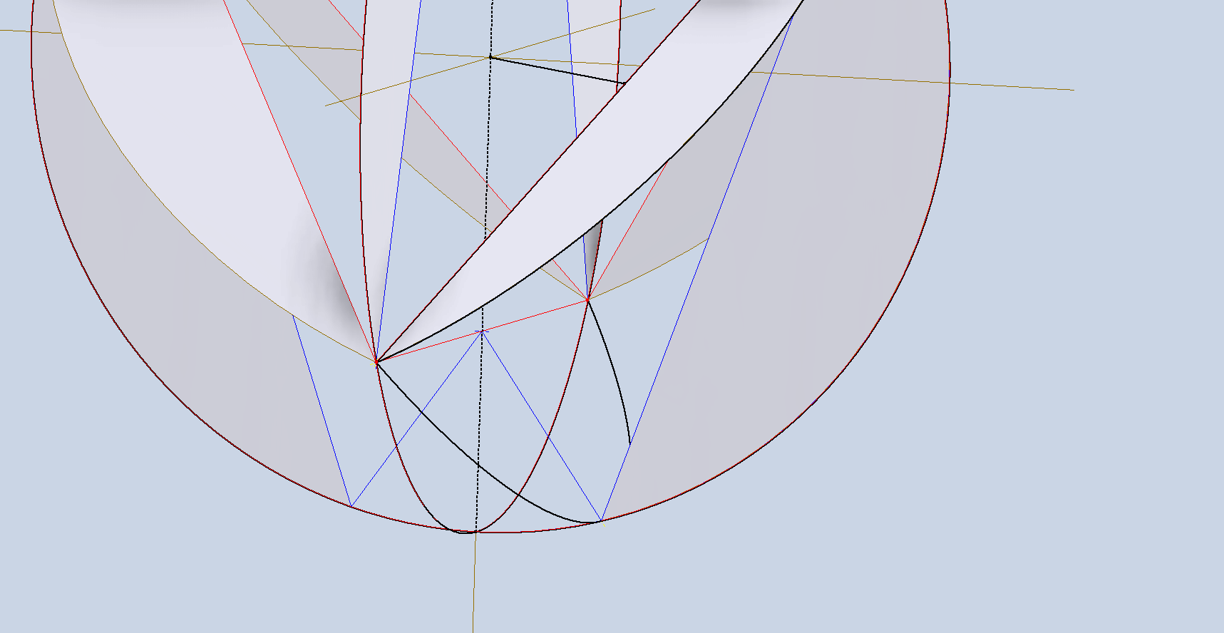
Now that we have all the duct openings located, we need to think about the duct cover surface lofts. First, we need to create a lofting guide rail, which is the arc shown in the first image above, along the smaller blue line drawn earlier. Essentially, rinse and repeat for all guide rails at the top and bottom, and loft each section in turn.
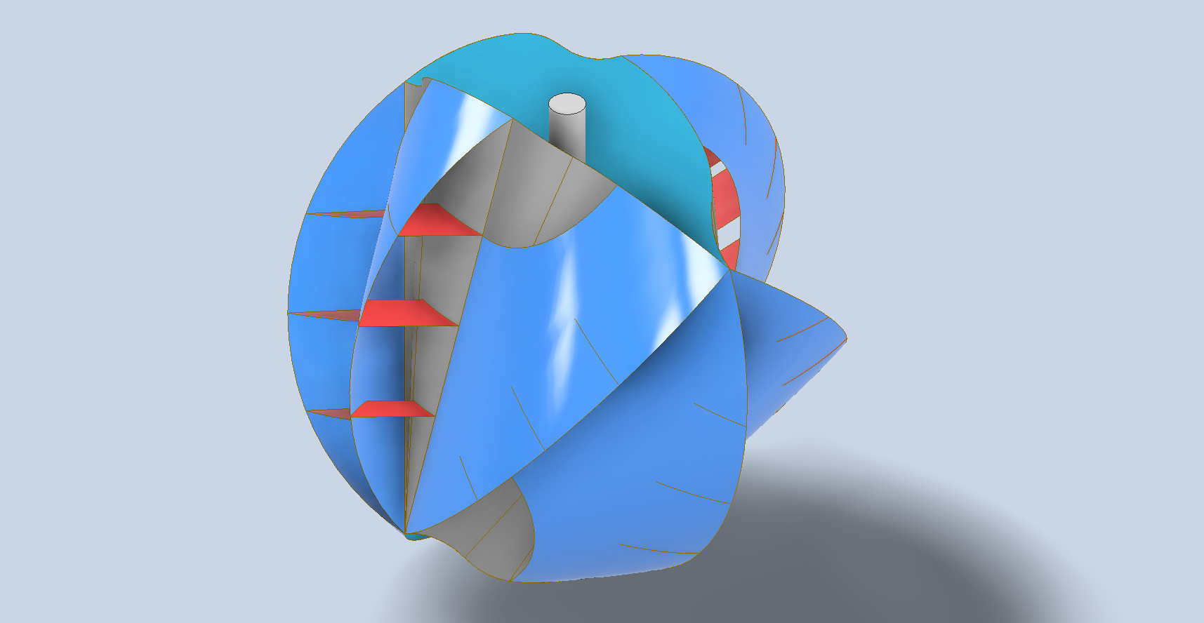
Once that is all done, you should end up with something similar to the above. I have shown a shaft through the vertical centre for reference. As mentioned earlier, this is just my interpretation of how a spherical wind turbine could be constructed.
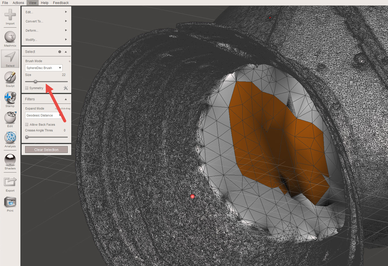
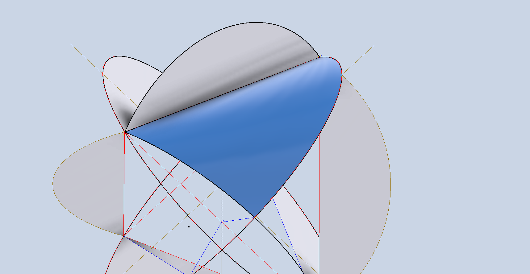
To check that the geometry is correct, it is advised to measure the area of each resulting surface, and they should all be exactly the same. Note the actual duct faces on the real object are shown cut back…if desired, this is easy to do with a surface setback 10 or 15 degrees and trimming the duct face. I didn’t do that, and I will explain further why.
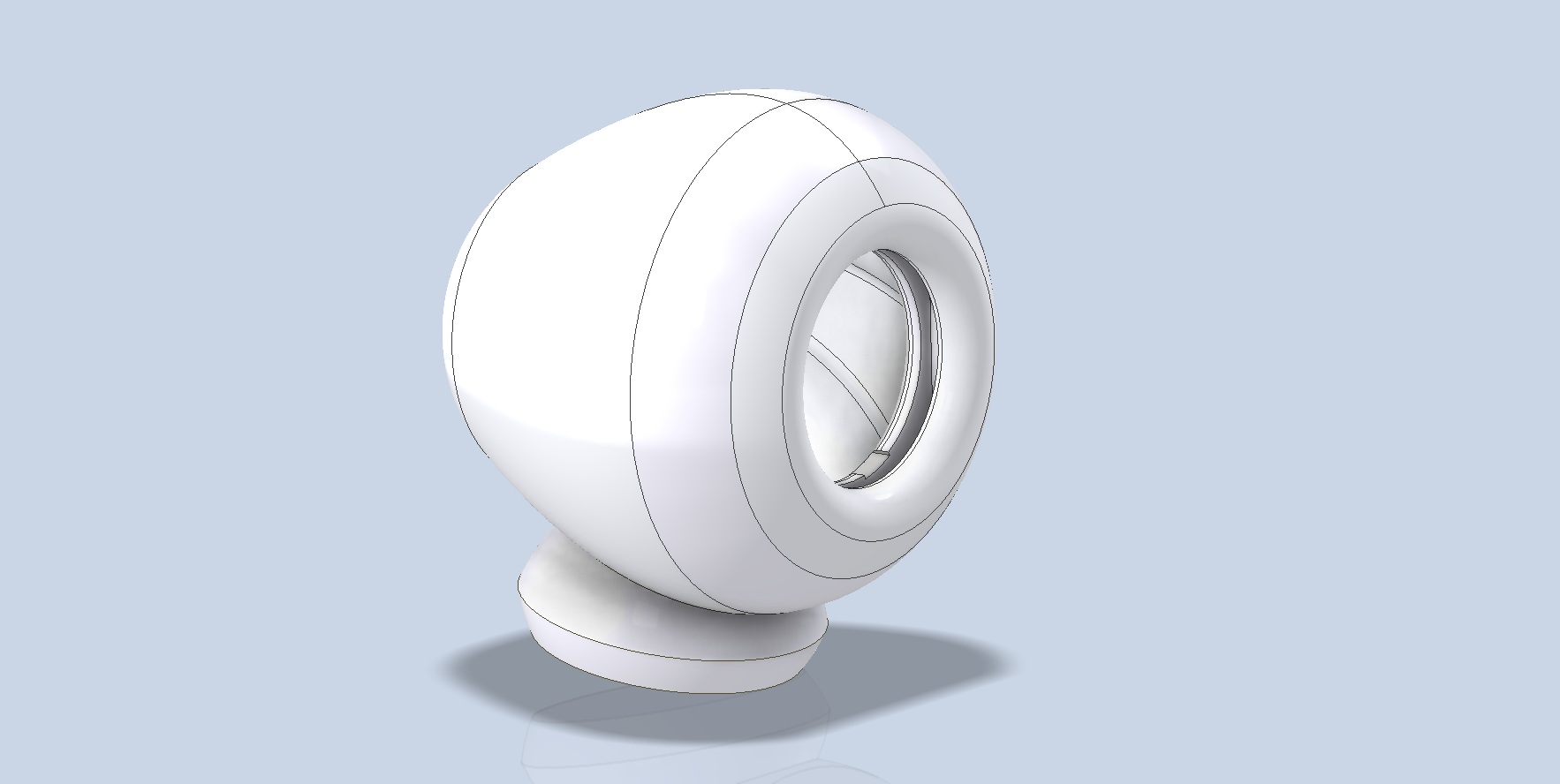
We now have the basic geometry from which we can explore options for finishing the ducts. I keep thinking about the enclosed duct space evident in the actual O-wind and Robert’s comments about the Venturi effect that seem absent from this model.
Well, I think I have a solution to that as well.
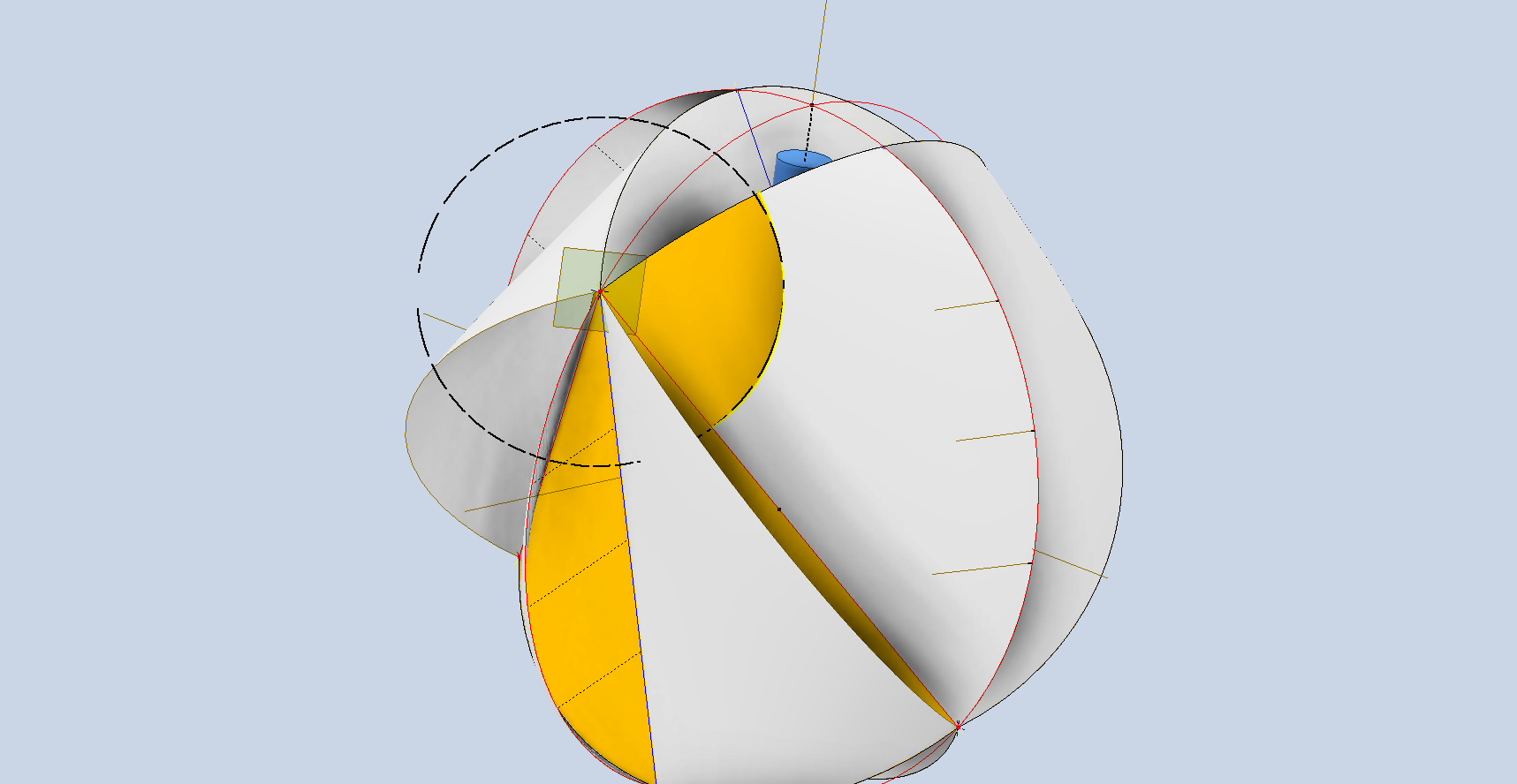
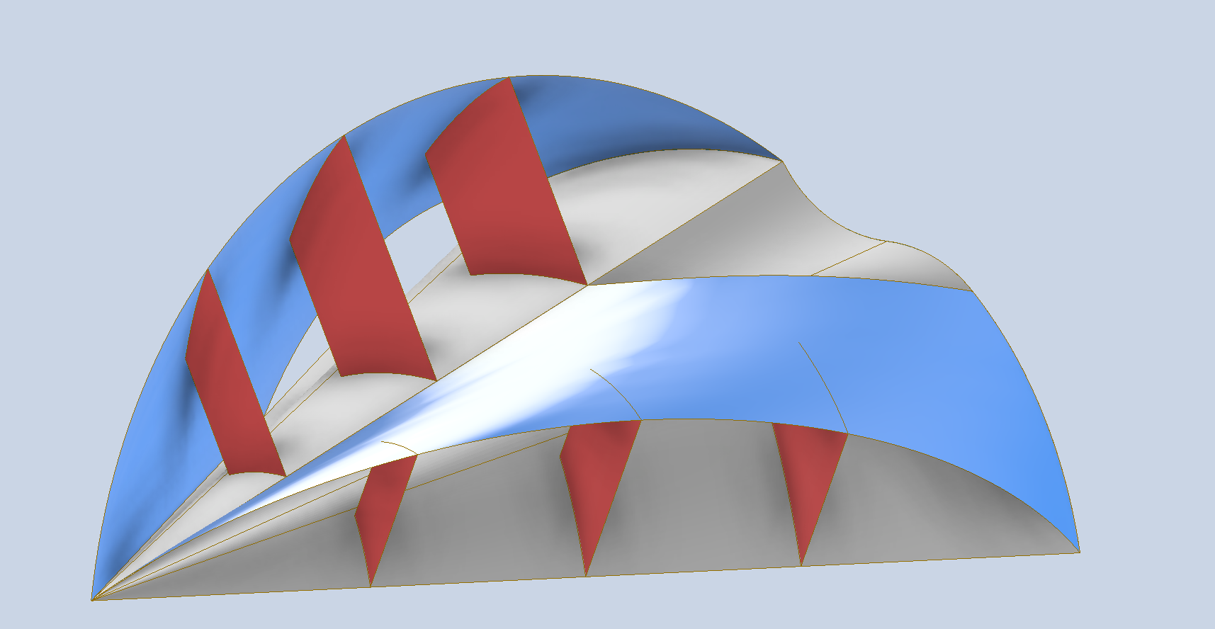
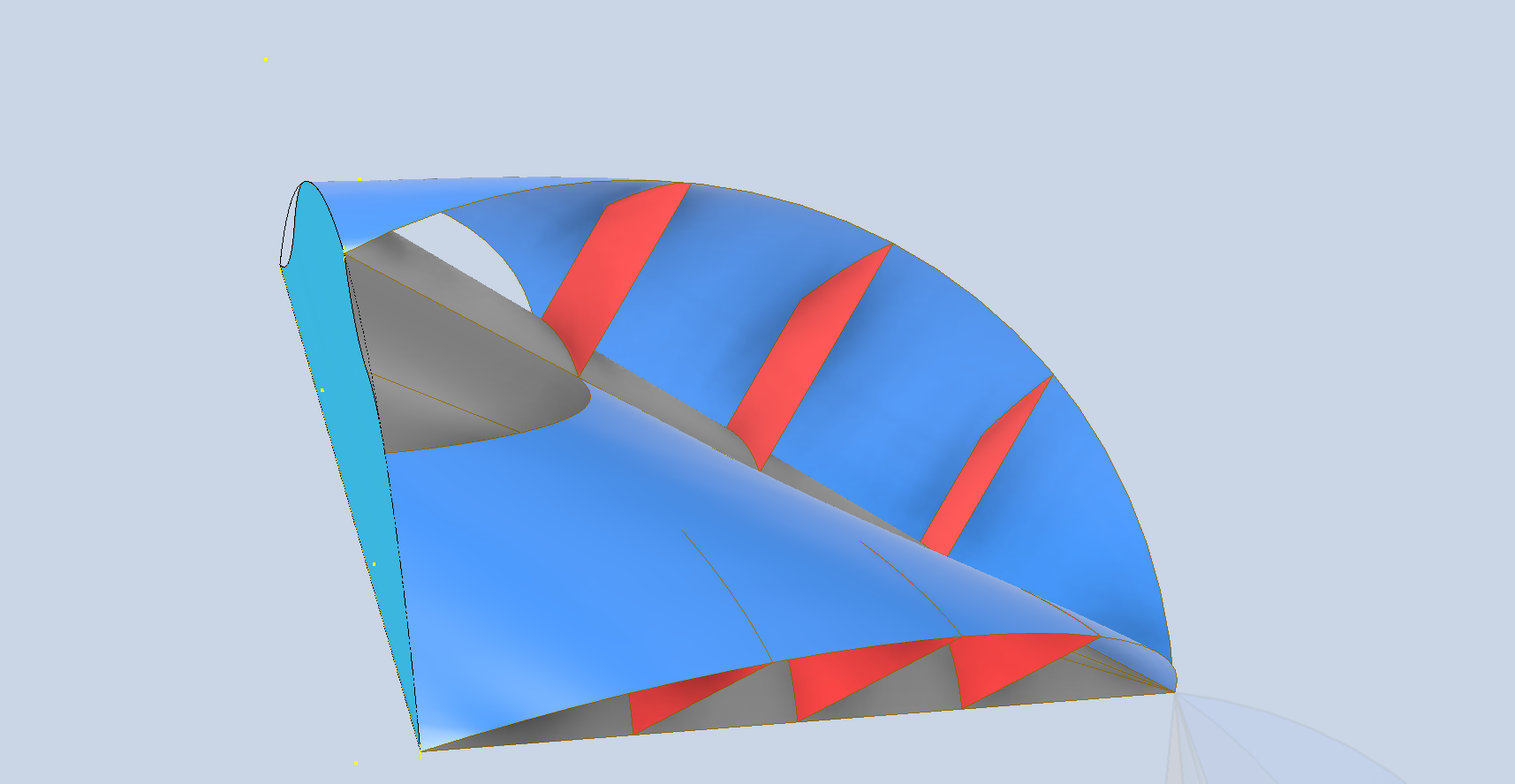
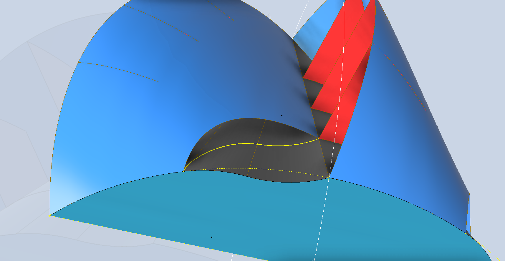
If we trim back the duct cover and create an opening as shown above, we can induce the Venturi Effect. This is simply done by creating a work plane on the vertex shown, tangent to the duct cover surface and drawing a circle for the cutout. The 3 baffle plates shown in red are only partially extruded so as not to cause too much turbulence, but sufficient to maintain structural integrity and direct airflow. For this proposal to work, there would be no benefit in cutting back the duct opening at an angle. The Venturi Effect applied in this manner would also add a degree of lift, further improving the performance and therefore efficiency of a spherical turbine of this type.
One additional benefit of this approach is that air circulates over the internal surfaces. If these surfaces include fins, we could create a heat sink effect, allowing the movement of the turbine to draw hot air away from the embedded generator. I have only modelled in one Duct as shown above for reference…it would be interesting to see what you can do with this design.
Disclaimer: I am reaching out to express my concerns regarding the recent unavailability of the model that Robert had generously made publicly accessible. I have a feeling that this change may have been prompted by someone’s request. I would like to clarify that this model draws inspiration from existing spherical wind turbines as part of a CAD development exercise. I hold a deep respect for the innovative work surrounding these turbines and wish to emphasise that my intention is not to reproduce or replicate their design. Thank you for considering my perspective on this matter.
Update 2nd April 2026:
I have made some minor changes to this design.
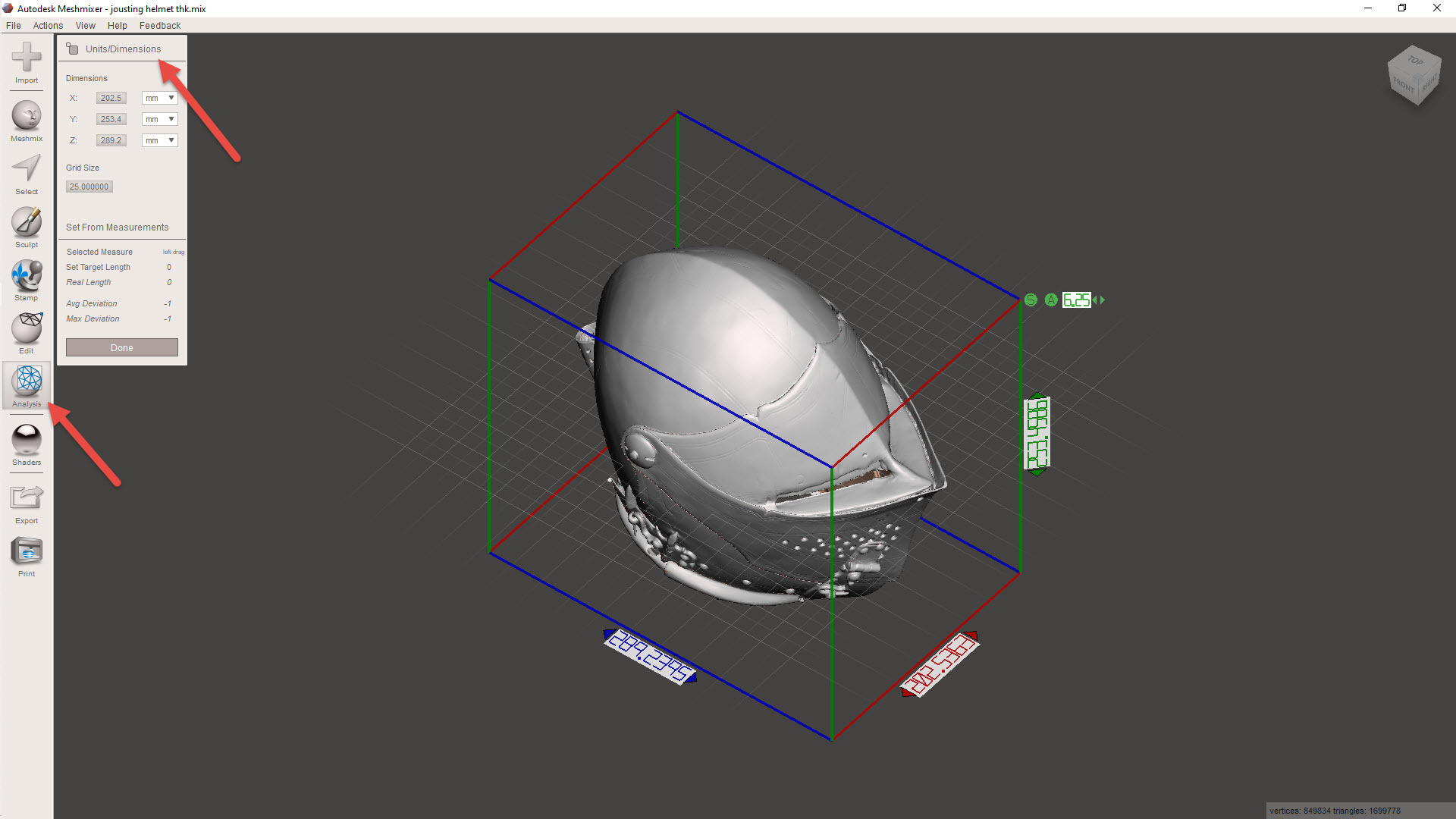
The Venturi effect opening is modelled with a slight curve added to the underlying surface to improve airflow. I have also adjusted the size to 225mm diameter, allowing more internal space for a flux generator while maintaining parameters suitable for 3D printing.
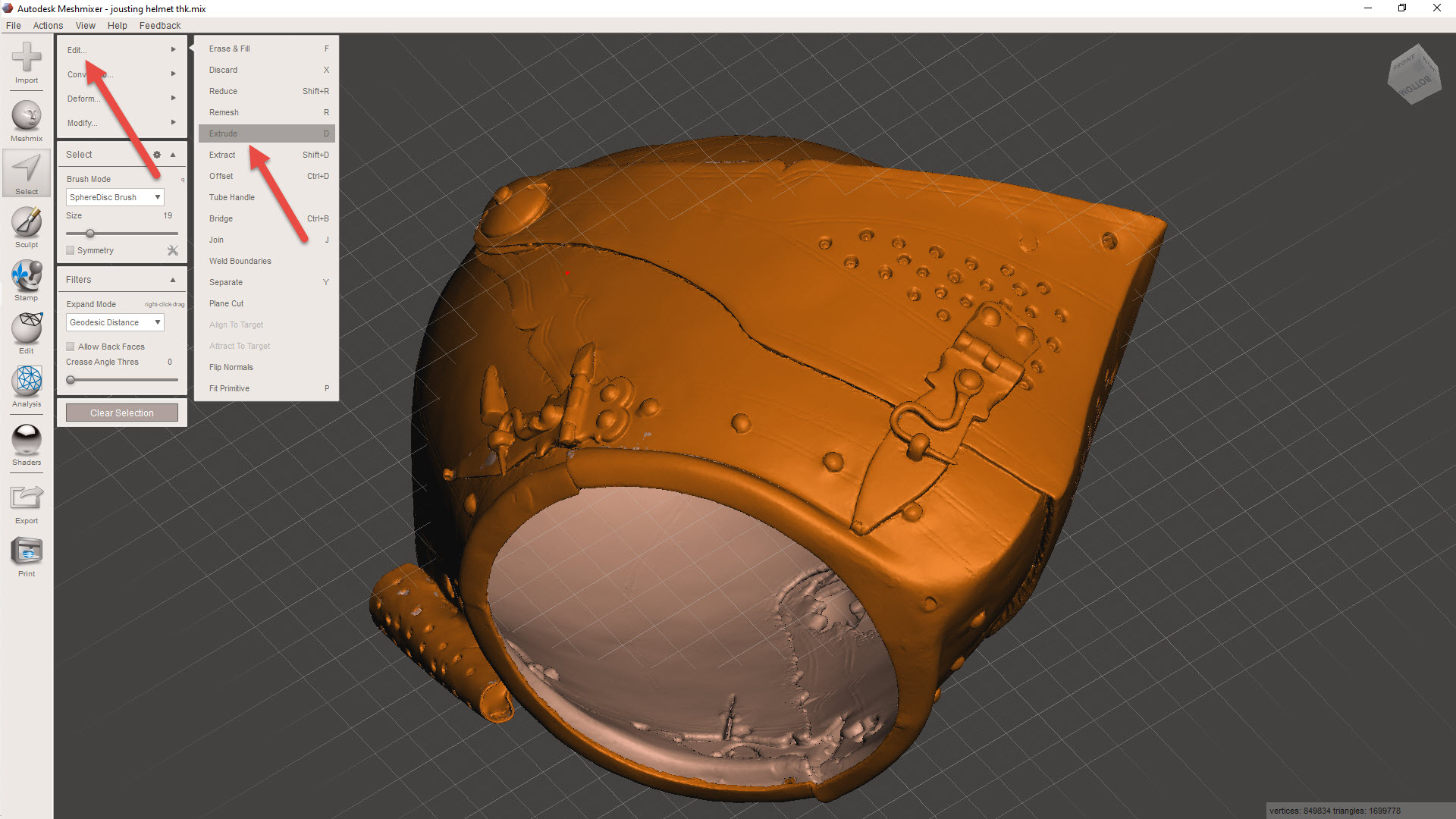
Also, I actually tilted the front duct face back 15 degrees to be more tangential to the adjacent surface. The entire assembly comprises 4 parts; 2 as drawn on the left and 2 to opposite hand on the right.
In this image, you can see that the exit profile has become more uniform with the addition of the curved profile. This is still a surface model, and each quadrant is designed to be compatible with a 3D printer with a bed size of 254 mm x 254 mm. The files for this latest version start with the prefix OMNI 11.
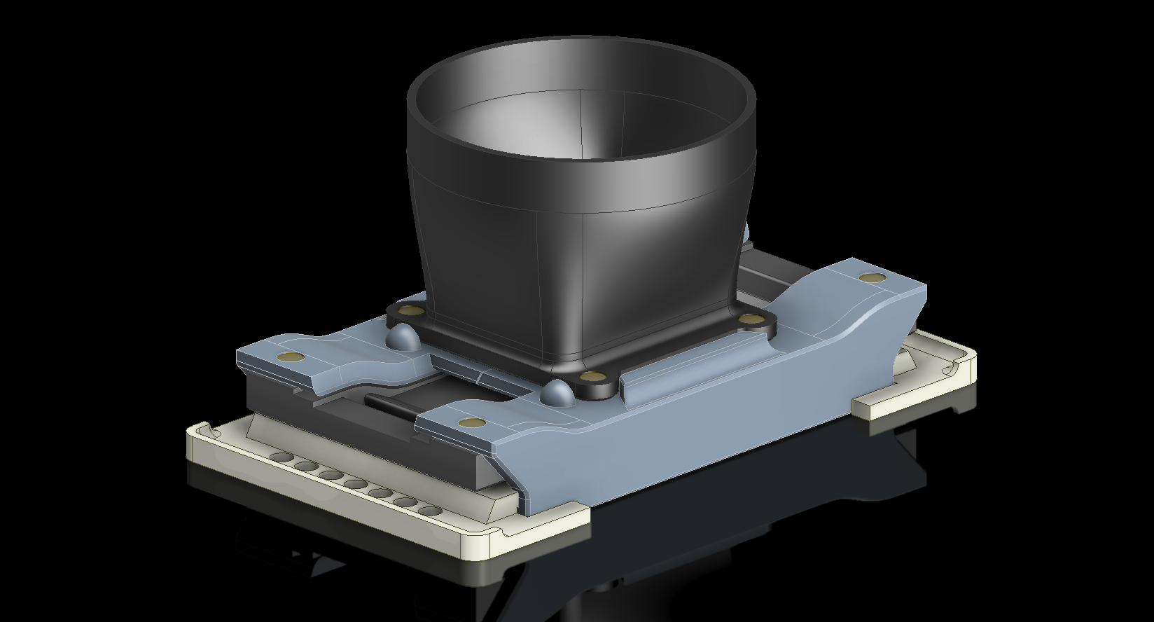
Apply 1.2mm thickness to the primary surfaces to obtain a solid, printable turbine, like this (not available for download)…
I have decided to make this model available as a free download for others to explore the fascinating world of CAD and its application in wind turbine design. For personal and educational uses only. The Omni 10 CAD model is 190mm in diameter, the Omni 11 is 225mm dia and are available as 3D DWG and IGES formats. DOWNLOAD LINK
Please consider making a small donation to help support my work on Aviation projects. [PAYPAL LINK]… thanking you in advance..
Inquiries as usual to hughtechnotes@gmail.com