Technote: Complex Surface Hole Location

Technote: Positioning Holes in Complex Surfaces

When detailing the skin panels for aircraft it can be quite daunting trying to locate a series of holes accurately at a specified distance from the edge of the panel. Typically fillets to wings and horizontal stabilizers and transition pieces to vertical stabilizers are all complex surfaces.

In this example, we need a series of holes located 17.5 mm from the top and bottom edges. As you can see the surface at the top and the flange angle at the base varies.

The location of the first hole, top and bottom, is aligned vertically so we first create a workplane to determine the horizontal position of the first hole. Ultimately we will use a 3d intersection curve for the centre line of the holes which must first be determined by sweeping a circle profile sketch along the edge as a surface with the radius set to the required edge distance. Using a circular profile for the sweep ensures that any intersection point on the surface will be at the specified edge distance.

This swept surface is then trimmed to the first work plane to define the start point of the 3d surface intersection curve as shown.

The resulting 3d spline represents the line of the hole centres at 17.5mm from any point along the edge of the fillet.

We then apply a point and an axis (perpendicular to the surface) at this point to determine the hole direction. I suspect because it is not a regular surface the hole feature will not allow me to select the surface for direction. Use “Extend Start” when creating hole.

2017-07-11_10-03-21

To pattern the hole along the spline and be perpendicular to the surface create the array as shown below. Be sure to select the extended options for “Direction 1” and “Adjust”.

2017-07-11_10-04-34

Do the same for the top array of holes, resulting in 2 sets of holes aligned with the surface at 17.5 mm from the edge.

2017-07-11_10-07-10

This works for the vast majority of riveted panel connections where locally there is a degreee of flatness between the matching parts. In instances, where there is extreme curvature of the connecting faces the radius of the extruded circle would have to be adjusted accordingly.

Hoppers: Surface Model for Mass Containment

Hoppers: Surface Modelling for Mass Containment:

Although not directly associated with aircraft design there are inherent modelling techniques equally applicable to many aspects of aviation. The techniques relate to surface modelling for the containment of a known mass or volume. In each case, the criterion is the specified volume or mass that ultimately defines the size and shape of the container.

hopper-1

This particular hopper is for a Transfer car used to feed Steel Plant Coke Ovens with coal. The development of this hopper combines surface and solid objects in a single multi-part model that is configurable via a dialogue populated wth the key parameters. Surface modelling can be used for various purposes; some of which I have covered in previous articles for the creation of sheet metal flanges, trimming solids and providing a boundary for extrusion or as a containment for a solid component; as I have used here.

hopper-master-01

This type of hopper is fed from an overhead bunker and releases the fill material through an aperture in the base. The mass volume is modelled according to industry specifications that define the slope of the poured coal defined by the size of the top bunker opening.

The surface represents the containment boundary which has zero volume and zero mass therefore by definition will ensure that the only properties recorded for mass and volume in the 3d model relate only to the fill material. The image above shows some of the key parameters used to model this hopper as a part file with an ilogic form to make it easier to adjust the parameters to suit the project design.

2013-09-17_121727

The gray values for the Coal Volume and the Centre of Gravity are the results calculated from the physical dimensions of the coal mass and the containing surface model. Once the correct dimensional and mass properties are determined the surface objects are extrapolated using the “Make Component” command in Inventor which creates a separate derived part file and also (optional) includes the part file in an assembly placed at the original coordinates. In the surface part file we simply thicken the surface to generate the solid plate material that will form the structural body of the finished hopper.

hopmaster01assemblya

This is a very basic introduction to using surfaces where the mass or volume of a fill material is the critical component. On some forums, similar questions have been asked for complete hoppers where programmed solutions are offered to subtract all the structural objects to derive the fill mass and volume. By using surfaces with zero mass and volume to contain the fill there is no need for any programming solutions. There are a few ilogic basic routines included in this example for formula calculations and shifting the location of the bunker output. Another example just for reference is the casing for a screwfeeder:

400 - Streams 1 & 3.png

Surfaces are extraordinarily versatile with many applications, only some of which have been mentioned in this blog. For this example, we could extend the technique to modelling fuel tanks, hydraulics and oil tanks where the volume and mass are critical.

Project Cad Technote: Sheet Metal Bending in CAD

Project Cad Technote: Sheet Metal Bending in CAD.

Sheet Metal Work is an interesting subject to which I could no doubt devote an entire blog to. Fortunately for us we don’t have to as this topic is covered in detail by the many professionals working in this industry.

However understanding some of the key principles is imperative to ensure that our CAD models created from the aviation manufacturers drawings are correct as the dimensions given do not always suit the CAD development process.

One particular aspect relates to something the Sheet Metal guys refer to as the Outside Setback. The Outside Setback is the distance from the apex of the outside mold lines to the tangent point of the outside radius. When the sheet metal is bent the inside radius pulls the edge of the material away from the apex of the bend.

2015-08-30_12-39-11Typically on many occasions we will have a developed profile for the part which is to be bent to the required profile with only a few dimensions noted to achieve this including a bend coincidence point and angle.

2015-08-30_12-13-10The image on the left is indicative of many situations that arise when working with the manufacturers drawings. It is not unusual for a dimension to be given to the projected point at “A” which understandably is important to ensure the part mates properly with another.

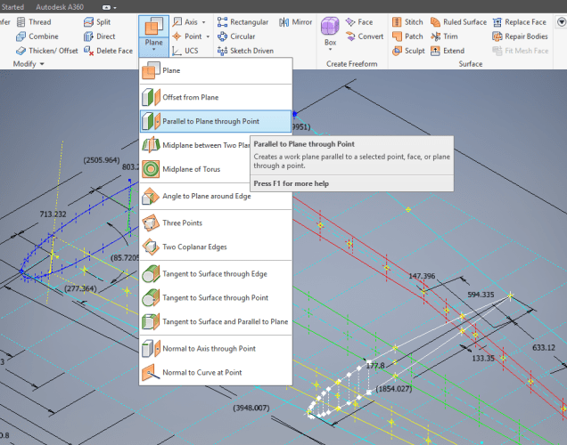
However in Inventor; for example; we only have selections at 1,2 & 3 for “folding” a part from a development sketch and no option to define the stated “Dim” to the point of coincidence; which therefore may not provide the desired result. We may of course have the angle, material thickness and usually the inside radius.

2015-08-30_12-19-11
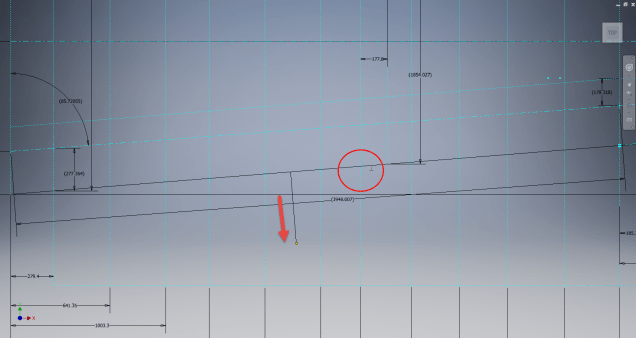
Its not practical to select points 1 & 2 but it may be possible to use point 3 if we know the OSSB dimension.

In Inventor this is the middle option from the sheet metal fold dialogue. In this case we have specified the complimentary angle (97 degrees).

In order for this to work we need to calculate the dimension OSSB. The smart guys in the sheet metal industry have this stuff all worked out and have an easy equation that we can use to ensure consistent accurate results.

2015-08-30_12-20-05

B> denotes the complimentary angle which must be less than 170 degrees.

IR is the Inside radius and MT is the material thickness. (the dot in the middle by the way is multiplication).

2015-08-30_12-25-18From this equation we derive the value for OSSB which we will deduct from the Dim value provided on the drawings, thus giving us the correct location of the fold line at point 3 above.

In this example the dimension from the manufacturers drawing is stated from the hole center, which has been adjusted to locate point 3 by deducting the value OSSB.

It works perfectly and we now have a folded bracket from a development plan that complies with the stated drawing dimensions.

I should note that some CAD products take this into account and provide the necessary options for developing this folded model but where we have limitations a touch of maths goes a long way to achieving the desired result.

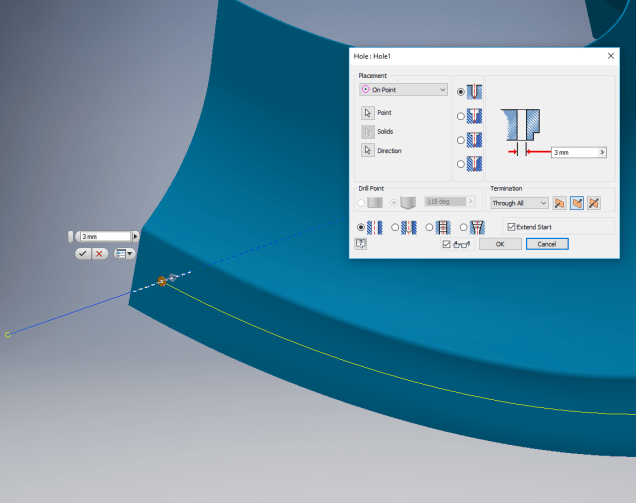
In this example the hole is very close to the bend causing a slight deformation. This could initially be drilled to a smaller diameter and reamed after bending or we could simply use a smaller bend radius; if permissible!