The Real Value of the CAD/Ordinate Datasets: Often Overlooked!
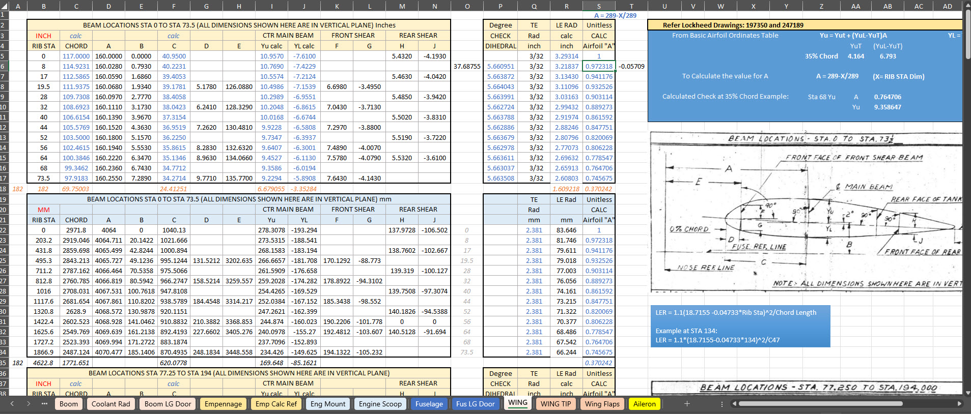
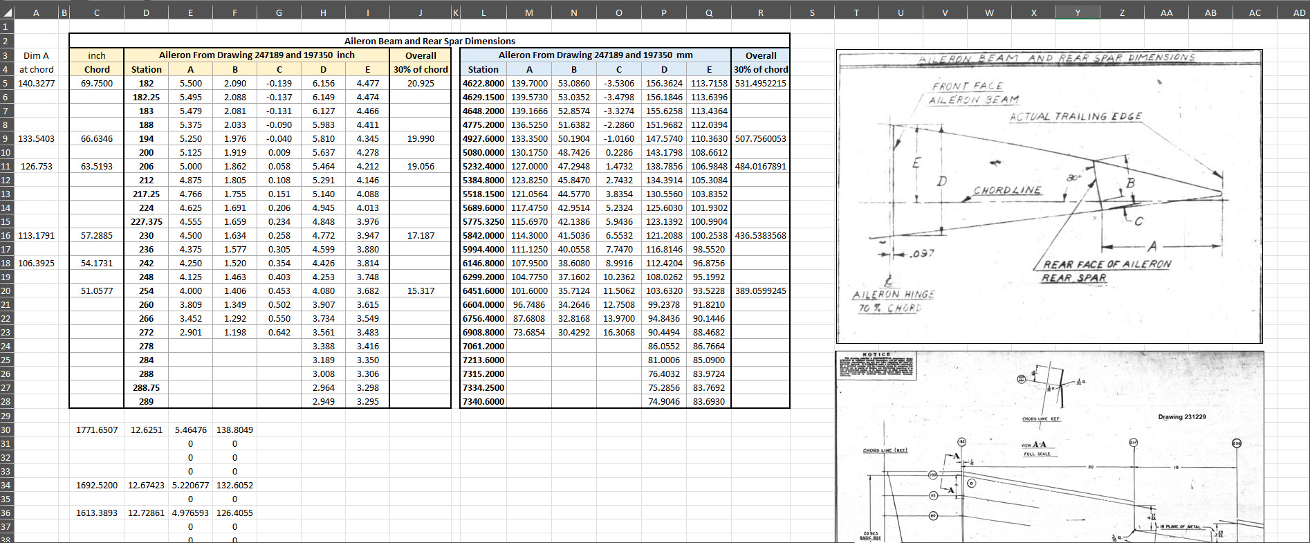
For many of my aircraft projects listed on the CAD+Blueprints tab, I offer comprehensive datasets of ordinate dimensional data in inches and millimetres listed in Excel spreadsheet tables. This data is extracted directly from original blueprints, verified by development in CAD, and, in many cases, verified by accurate recalculation.
This is the real value of these datasets, many of which took days or even weeks to compile. As an Excel spreadsheet, the X,Y, Z data is easily cut and pasted into your CAD system of choice, instantly providing point datasets that define fuselage frames, wing ribs, cabin contours and so on. It is that easy and saves you many days and weeks of trawling through blueprints and extracting the data piece by piece yourself.
The format of the tables replicates the same layouts as the data presented on the original blueprints, where applicable. So the data is easily cross-referenced for verification.
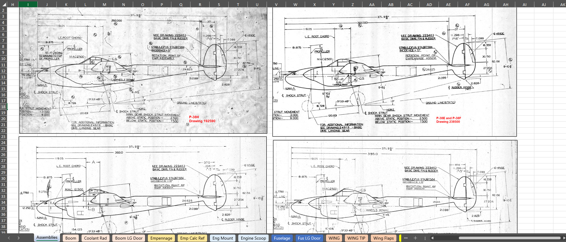
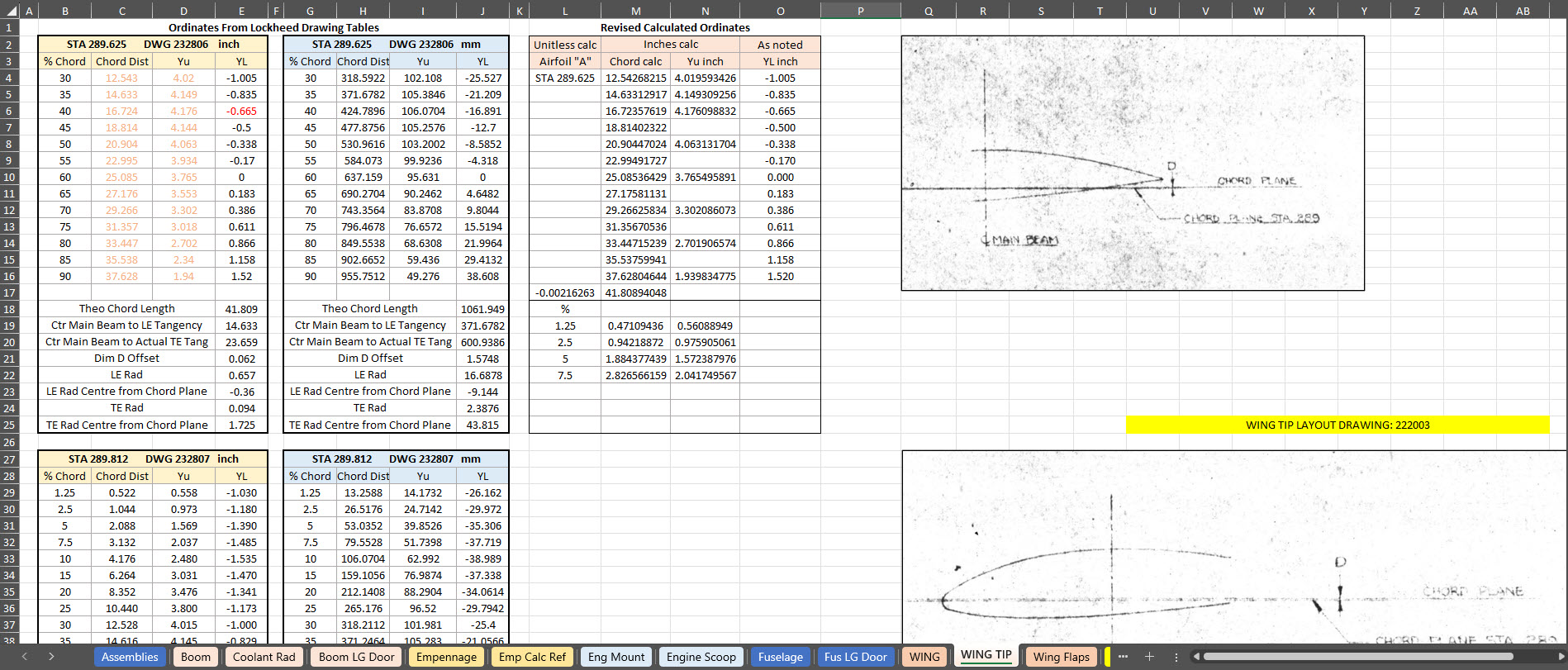
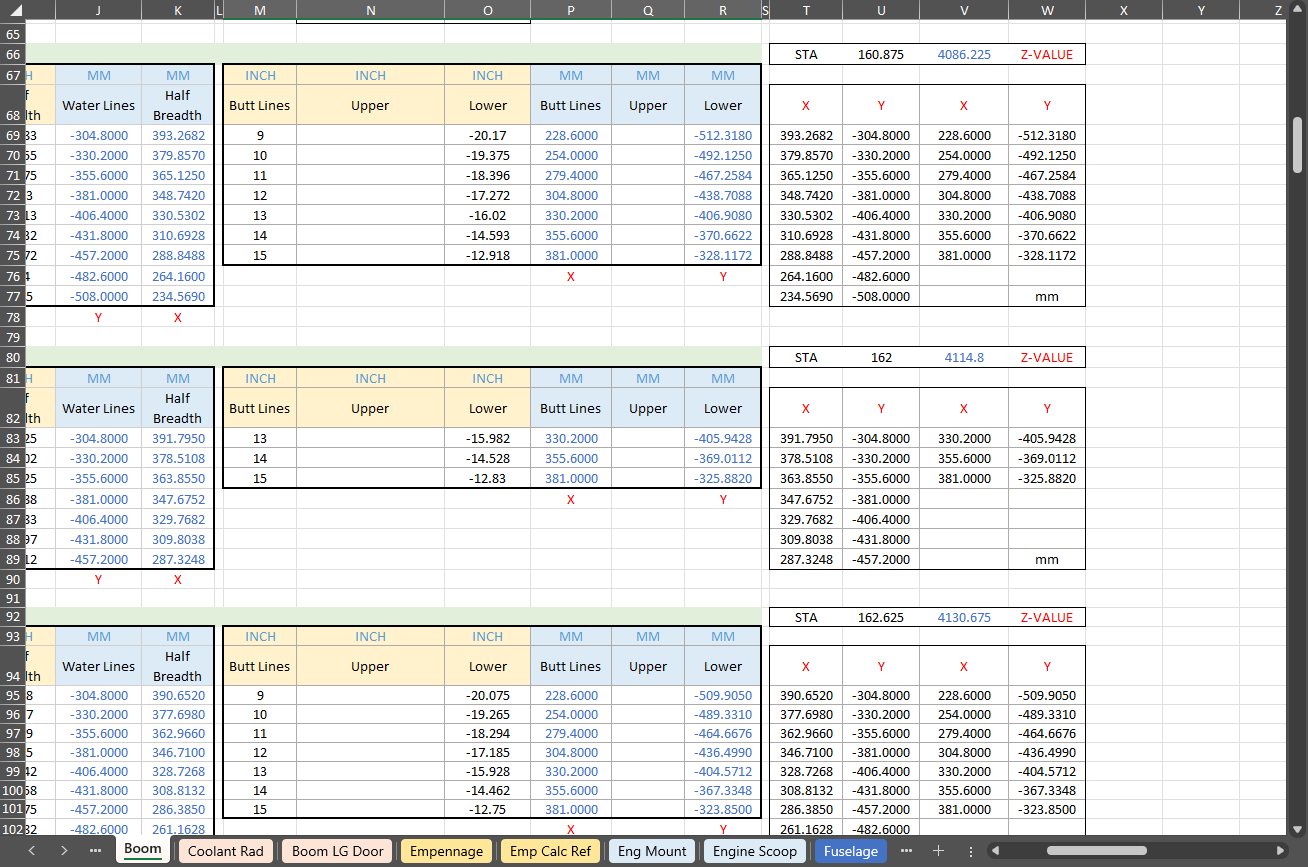
To give you a clearer picture of what to anticipate, the screenshots above showcase typical coordinate datasets for the P-38, presented in an Excel spreadsheet format. These datasets feature organised columns and rows, making it easy to navigate through the intricate details associated with the P-38’s specifications and performance metrics.
There is one caveat: there is a small cost involved. I have overhead expenses for software licenses and for running this blog Ad-free. I rely on donations and the sale of datasets like this to help cover those ongoing costs.
The Excel spreadsheets provided are fully adaptable and not restricted in any way, allowing you to modify them to meet your specific needs.
I wanted to take a moment to share this brief article that emphasises the true value of the CAD/Ordinate datasets. My aim is to shed light on how these datasets can be instrumental in enhancing your project and productivity. With their rich features and detailed information, the CAD/Ordinate datasets can provide invaluable insights and support, making your work not only more efficient but also more effective.
All datasets are supplemented with CAD models derived from them in commonly used formats, such as DWG, to assist you further.
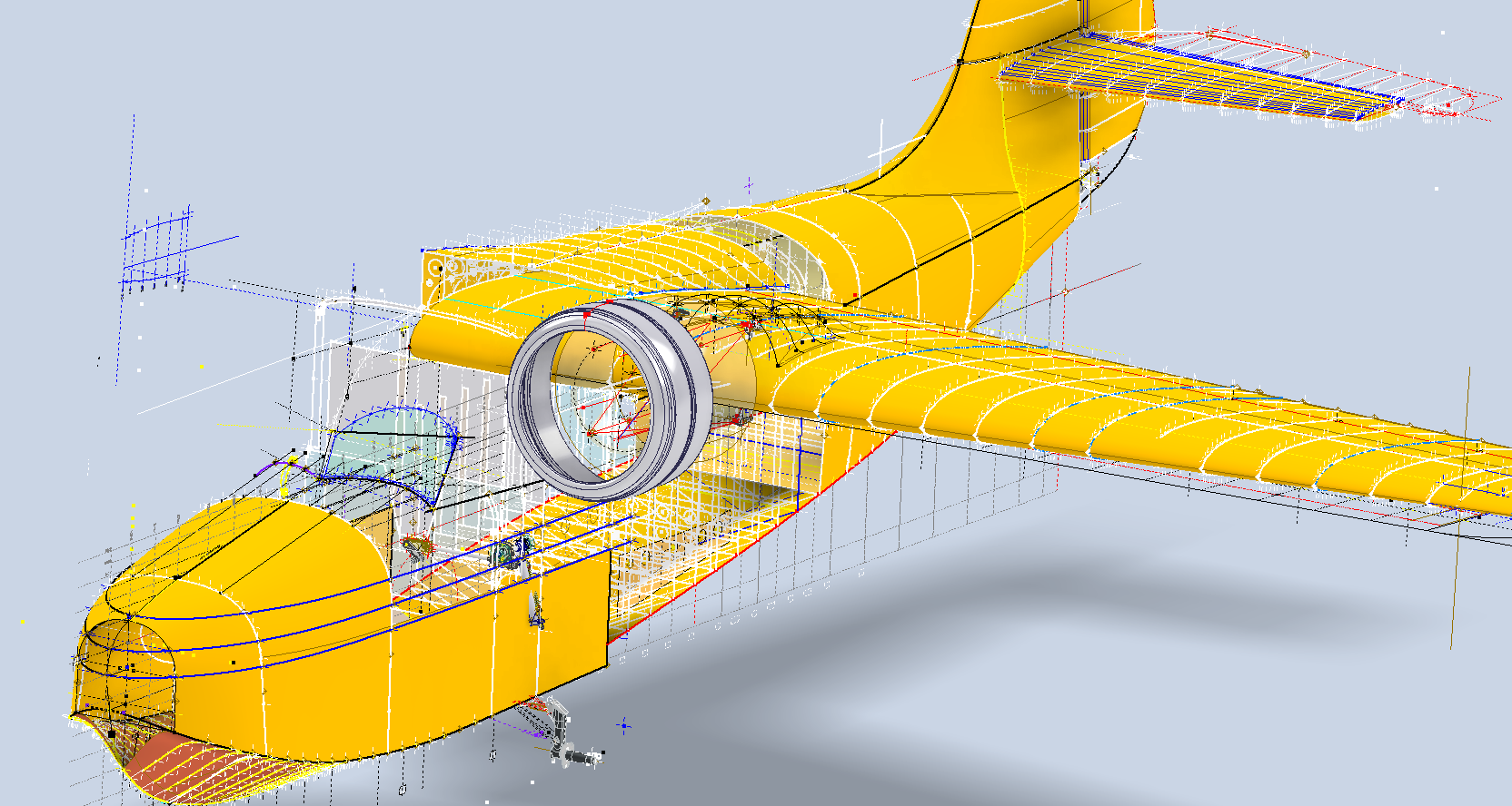
I am currently working on a series of updates to the Grumman Goose project. This will include full surface modelling and comprehensive assemblies for the Landing Gear and Engine Nacelle.
The surface panelling is being implemented in a series of carefully planned stages to effectively accommodate the significant variations in surface contours that occur along its length. To achieve optimal curvature continuity for the surface panels, I have undertaken the modelling of multiple fairing contours, each meticulously designed to ensure a seamless integration with the underlying structure. This approach not only enhances the aesthetic appeal but also ensures structural integrity, as it allows for precise adjustments that align with the dynamic shifts in the surface geometry.
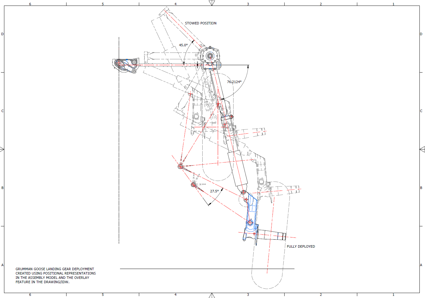
The Landing Gear will be fully modelled, including detailed working mechanisms that will later be the driving parameters for a deployment simulation.
I am currently exploring various options for replicating the components as high-quality 3D prints. This initiative is part of a future project aimed at demonstrating operational criteria in a tangible, physical form. I plan to utilise advanced 3D printing techniques and materials to ensure accuracy and durability in the prototypes. Additionally, I will conduct thorough testing to assess their functionality and performance. This approach will not only enhance the visual presentation but also provide a practical, hands-on experience.
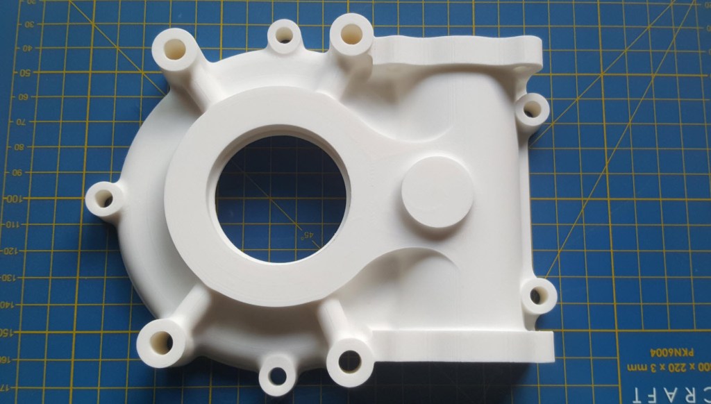
As a basic test to check the viability of the project, I 3D printed the front cover of the secondary gearbox to see how it worked out.
Part #9632 front cover. Printed on an Elegoo Centauri with 0.12 layer height using PLA+ filament. The surface was surprisingly smooth with good dimensional accuracy. Eventually, I will print all the internal gears and check operational criteria.
The engine nacelle is still very much a work in progress, which I will feature in a future post. Following the example of the SU-31 project, the Grumman Goose will also be available in a 1/16 scale version suitable for RC projects.
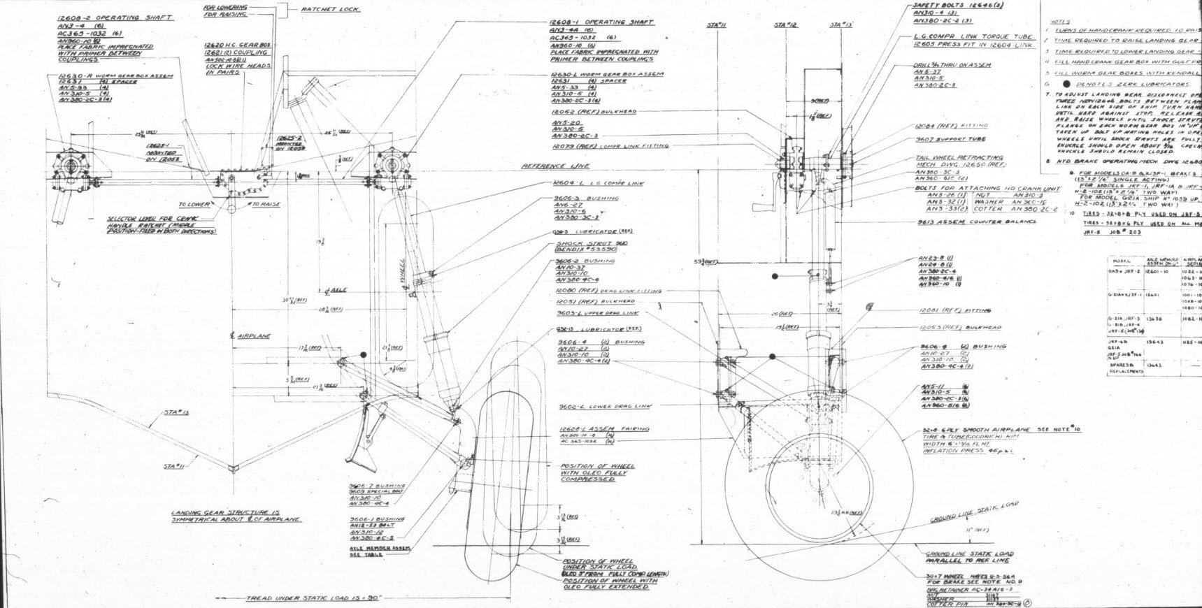
For reference, this is the Landing Gear Assembly Drawing #12600.
For quick renderings that are perfect for blog posts, I typically prefer KeyShot. It provides an intuitive workflow and a large library of environments and materials. However, the trial version has some limitations: you cannot save projects or export a rendered image, except as a screenshot. When I was recently asked to produce high-quality renders of the Republic JB2 for a museum display, I was uncertain about how to accomplish this.
These products are very expensive and far exceed my budget, so I urgently needed to find a solution. That’s when I discovered Autodesk VRED. I downloaded the software along with the accompanying asset library, and to my surprise, the trial version is fully functional. It allows me to save projects and create high-resolution renders, and it runs for 30 days.
Autodesk Vred retails at around $14000, which is extraordinarily expensive, but it is aimed primarily at the Automotive industry. Consequently, the product is packed full of features and limitless options on environments, materials, lighting and camera setups. It truly is a comprehensive and, to some degree, rather complex product, so there is a steep learning curve.
Undeterred, I set to work by reviewing tutorials, YouTube videos, and various online resources. Over the course of six days, I gained a deeper understanding of the nuances of VRED rendering. While I’m not an expert yet, the test renders started to come together, culminating in the images showcased below.
These images are not final, as I still need to work on the texture mapping and apply materials to some internal components. However, they demonstrate that it is possible to achieve satisfactory results in a relatively short time. Although the product has a steep learning curve, it encourages you to deepen your understanding of materials, textures, and lighting, which ultimately enhances your grasp of rendering processes.
I highly recommend that anyone interested in creating renders try Autodesk VRED. It offers the full functionality of a high-end rendering product, including the ability to save your projects and export high-resolution renders. The availability of a 30-day trial version is exceptional—Keyshot, take note!
I want to clarify that I have no affiliation with Autodesk, but when it comes to the accessibility of professional products, Autodesk is unparalleled. I have no problems recommending worthwhile products, like this one.
This project aims to document and preserve dimensional data for historical aircraft, currently working on models such as the P-47, FM2, and Grumman Goose, alongside two glider projects. Utilizing archival blueprints—often of suboptimal quality—we employ precise digital reconstruction techniques to ensure the accuracy of aircraft structural data. The goal is to support restoration efforts, research, and educational initiatives in aviation history.
3. Objectives:
Digitally reconstruct and verify the dimensional data of historic aircraft.
Provide comprehensive documentation for restoration, museum displays, and aerospace research.
Develop methodologies for extracting accurate data from degraded blueprints.
Expand the available reference library for aviation researchers and engineers.
4. Significance & Impact:
Historical Preservation: Ensures that legacy aircraft remain accurately documented for future generations.
Educational Contribution: Supports aerospace research institutions and museums with validated technical data.
Collection and analysis of historical blueprints and microfilm archives.
Use of CAD software to recreate accurate aircraft structures.
Cross-referencing archival data with existing dimensional records.
Collaboration with restoration experts to validate findings.
6. Challenges & Solutions:
Suboptimal Blueprint Quality: Implement specialized image enhancement and measurement techniques.
Funding Limitations: Seek partnerships with aviation museums, historical organizations, and aerospace institutions.
Data Validation: Engage with experts to cross-check reconstructed aircraft dimensions.
7. Funding Request & Justification:
The project has been independently funded to date, but rising operational costs present financial challenges. Support is requested to sustain ongoing research, enhance documentation quality, and facilitate broader distribution to historical and aviation institutions.
8. Potential Collaborations & Sponsorships:
Aviation Museums: Partnerships for data preservation and restoration projects.
Educational Institutions: Opportunities for research integration and student engagement.
Aerospace Industry Experts: Validation and application of documented data.
Fellow Enthusiasts and Donors: Acknowledge contributions, engage in peer-to-peer discussion and provide technical support where applicable.
9. Conclusion:
This initiative offers a critical contribution to aviation history by preserving precise structural data of historical aircraft. With adequate funding and institutional partnerships, the project will continue advancing research and documentation efforts for aviation scholars and engineers.
—————————————————————————————————
Contact Hugh Thomson via email: hughtechnotes@gmail.com.
On the CAD/Blueprint resource page, I have compiled a list of Ordinate Dimensional studies for various aircraft. The purpose of these studies is to gather all known dimensional information in a format that can be easily transferred to any CAD system. Additionally, they serve as a dimensional check to verify the designer’s intent and assess the accuracy of data from different resources, including blueprints, manuals, and correspondence.
Let me give you an example:
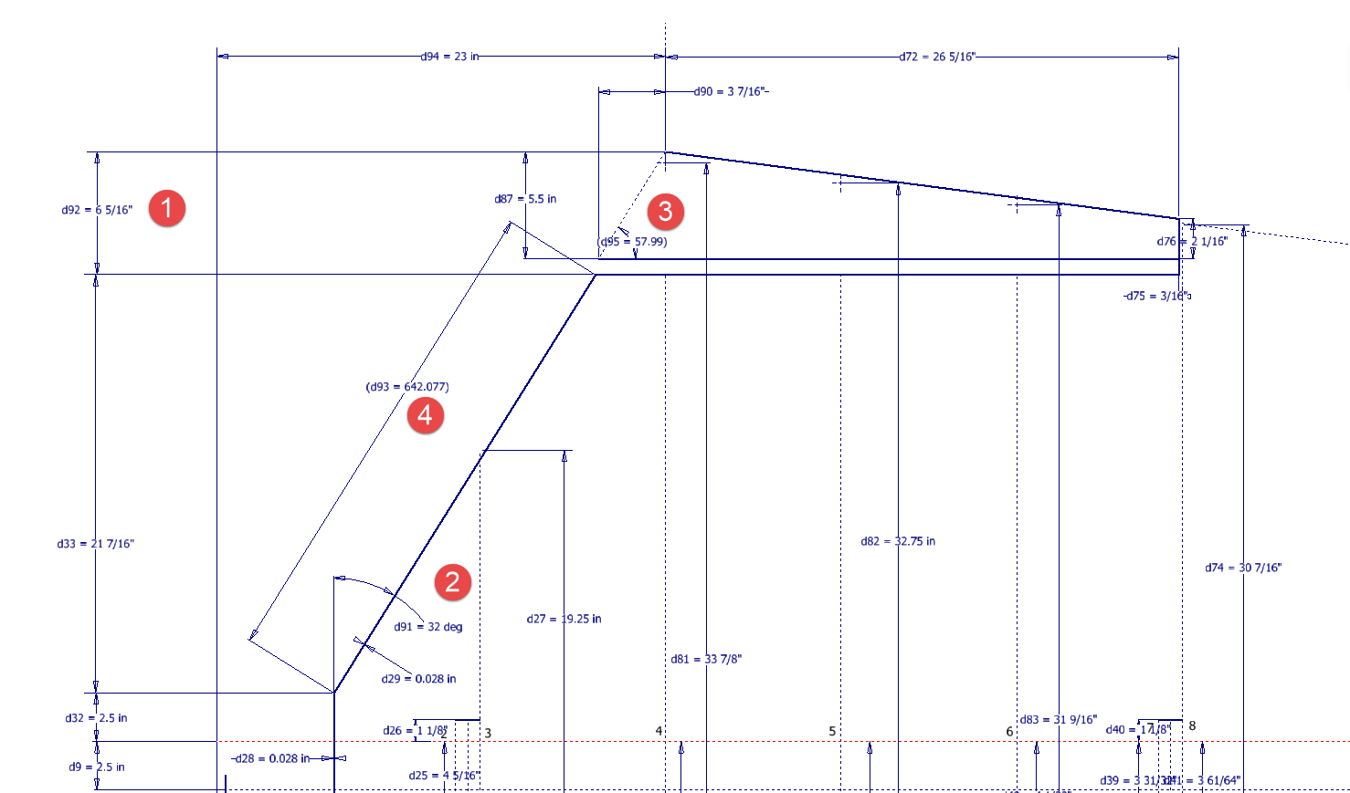
I am currently updating the CAD/ordinate dataset for the Grumman Goose and have already identified a few anomalies in the empennage. This document includes the layout study for the elevator, and you will notice that, based on the blueprint dimensions, the trim tab is incorrectly positioned.
At first glance, it may seem that the dimension labeled “1” is incorrect, as it appears to be the catalyst that causes the trim tab to go out of alignment. However, when we consider the length of the diagonal line labeled “4,” which measures 642.07 mm (25.27 inches), we find a discrepancy with the blueprint that specifies this dimension as 25 inches. Additionally, this measurement does not align with the chord dimension for the rib labeled “2.” As it stands, the angle of the sloping line appears to match at 32 degrees for both the trim tab and the elevator.
This type of issue frequently arises when working from blueprints for any aircraft project. To address it, further research is required, which will involve cross-referencing all part and sub-assembly blueprints in the affected area, reviewing general arrangement layouts, and consulting relevant manuals. It is essential to understand the design intent in order to develop the most likely solution. I have even extracted key information from correspondence that was important for the P-51 Mustang.
Small dimensional discrepancies are common in these projects, not only due to converting inch dimensions to millimeters but also because of typographical errors on the blueprints themselves.
The screenshots of the Ordinate spreadsheets display the dimensional information for the Horizontal Stabilizer and the Rudder. Several dimensions are highlighted in red, indicating errors on the blueprints that have been corrected. The dimensions marked in gray represent the measured dimensions from the CAD model. This discrepancy arises from the inherent accuracy of the specified dimensions, which may only be precise to 1/32″. As a result, minor deviations can occur during the CAD development process. Understanding these differences requires careful consideration of all key layout dimensions and material thicknesses, as they all influence the final derived dimensions. Nothing is taken for granted.
The CAD/Ordinate datasets compile all known dimensional information from various thoroughly researched sources, providing a comprehensive collection of data. This data is presented in editable spreadsheets, fully dimensioned drawings, and 2D/3D CAD drawings and models.
Elevator Layout Solution:
I have identified a solution regarding the layout dimensions. The dimension labeled as “1” is incorrect, but it is not the primary issue. Firstly, the Trim Tab has its own drawing #12530, which indicates that the overall length of the tab is 28.75″. This measurement is incorrect; it should be 29.75″. Additionally, other dimensions are also contributing factors.
In the bottom left corner, we find the specifications for the Hinge and Torque Tube, where two dimensions are marked with a tilde underscore to indicate that they are approximate. Generally, approximate dimensions are expected to be close to the actual measurements; however, that is not the case here. By adjusting the overall length of the Trim Tab along with modifying the approximate dimensions at the hinge torque, and also ensuring proper alignment with the known trailing edge, I have arrived at a workable and accurate solution.
Tech Tip: Using the Ordinate Spreadsheets:
I often get asked this and I have written about using the Ordinate spreadsheets before. Bumping it up to a more recent post, this one; I thought I would share a quick tip.
The Ordinate data spreadsheet is on the left, while the other is an empty spreadsheet that I use to paste data for a specific frame or rib that the CAD system can access. The empty spreadsheet just sits on my desktop, which makes it accessible.
Generally, the format of the data table is set out according to the original resource, which makes it easier to cross reference and check. This is not entirely ideal for CAD access as the X, Y coordinates are in rows and not in columns. The fix for that is easy, copy the data from the spreadsheet as required, select Paste Special in the destination spreadsheet making sure to select the “Values and Formats” and the “Transpose” options. The former ensures the data format remains the same and the purpose of the Transpose function is to convert data rows to columns. This gives us the data in X, Y columns ready for insert into the CAD system.
Note the “inch” header…I am using a millimetre template in my CAD system so I have to specify the unit of measure when I select from the first table. By the way, there is a second table that has all those values converted to millimeter anyway, so we could easily use that…in this case, you would not require a header row.
In other datasets, I have developed additional data tables in the spreadsheet, where I have transposed columns for the X, Y, and Z coordinates, such as those for the P-39.
I receive a lot of feedback from users about the spreadsheets, specifically regarding the time they save on projects since they do not have to manually input data themselves.
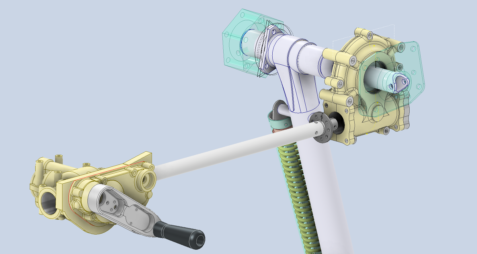
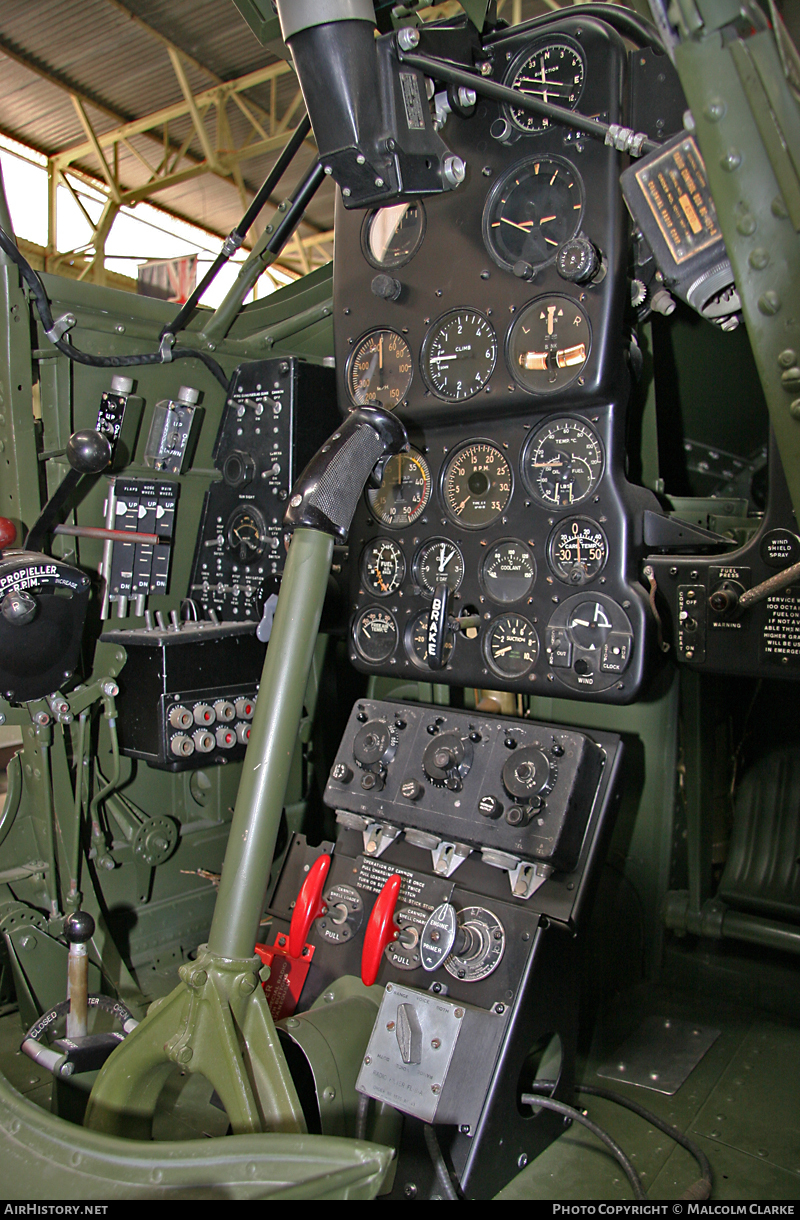
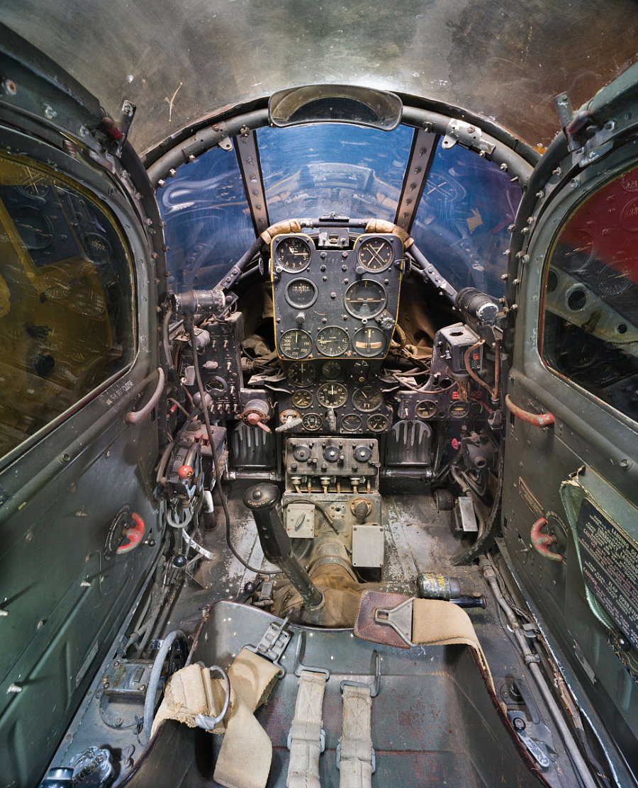
Working on the controls and instruments for the P-39 spawned a plethora of questions about how these controls actually worked. So I endeavored to incorporate the inner workings in the Trim Tab Control CAD models. This was specifically to get a better understanding of how they work. This was not a mandated requirement. The initial work scope was replicating the external components for a static display P-39 restoration.
Often enough in museums and private collections, we only see the external controls. For many, this is all they want to see. But what if we also see the internal gears, pulleys, shafts, and bearings to understand how they operate? This is exactly where I now want to go with my future projects.
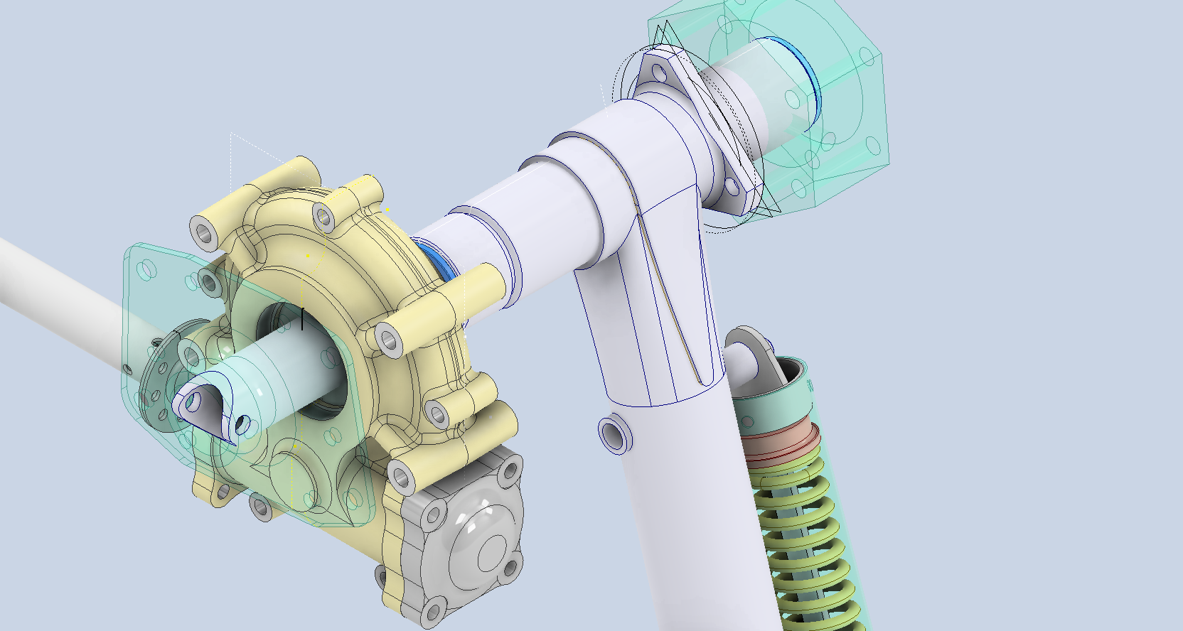
The Trim Tab controls for the Elevator, Rudder and Aileron are already modelled for the P-39 including the internal components. These dials and controls are currently being manufactured for the restoration project. The decision has now been made to incorporate the working mechanisms as functional replicas. This is great and will actually have some form of function, however, the mystery of operation still eludes the operator. I want to take this a step further and produce desktop models with Clearview casings so that the internals are visible. The exact method is still under review. It will mainly comprise 3D printing techniques for the main components attached to perspex casings.
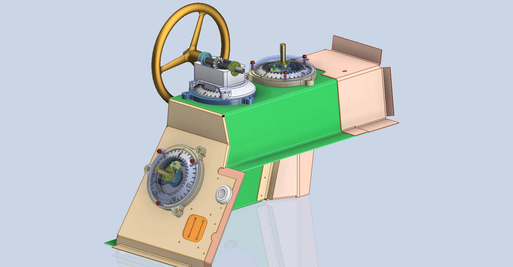
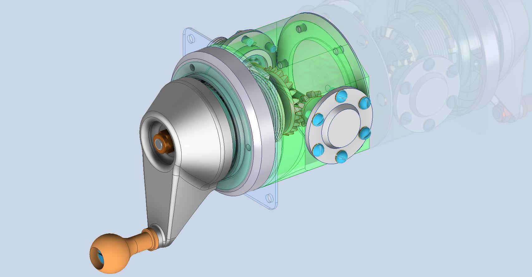
The dials for all 3 controls are similar with the Rudder and Aileron dials operated by a control knob (not shown) and the Elevator Tab controlled by a wheel as shown. At the base of each control dial there is a sprocket for a short Roller Chain which in turn is attached to operating cables. Out of curiosity I decided to have a look at other aircraft to see how alternative mechanisms were developed for the P-51 and the FM2.
For the P-51 the Trim tab controls are comparable in their operation with the internal gearing arrangements but differ slightly in design.
The dials for the Aileron, Elevator and Rudder are all similar to the CAD model shown. The Elevator and Rudder have cable drums attached to a long shaft for direct cable operation whilst the Aileron has a chain sprocket similar to the P-39 Trim Tab controls.
The plan for the P-51 is to fully model all the components in the assembly shown, complete with cables and chains to simulate operation.
A small point of interest; the various aircraft designed by the same manufacturer often share common parts; for example the NAA drawings for the B-25 share the same Trim Tab control knobs as the P-51 and listed accordingly. For some reason, the P-51 drawings do not reciprocate.
If you can’t find drawings for a particular part, check collections for other aircraft by the same manufacturer. Occasionally, this can be worthwhile. Similarly, with Grumman, many parts were shared with the FM2 and the Grumman Goose.
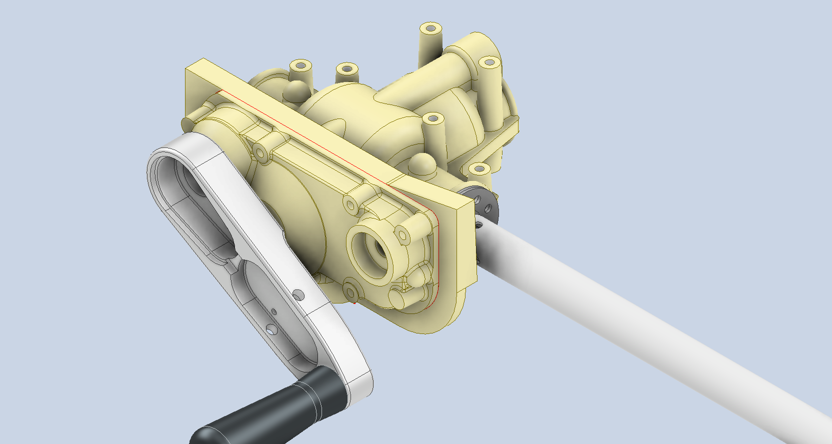
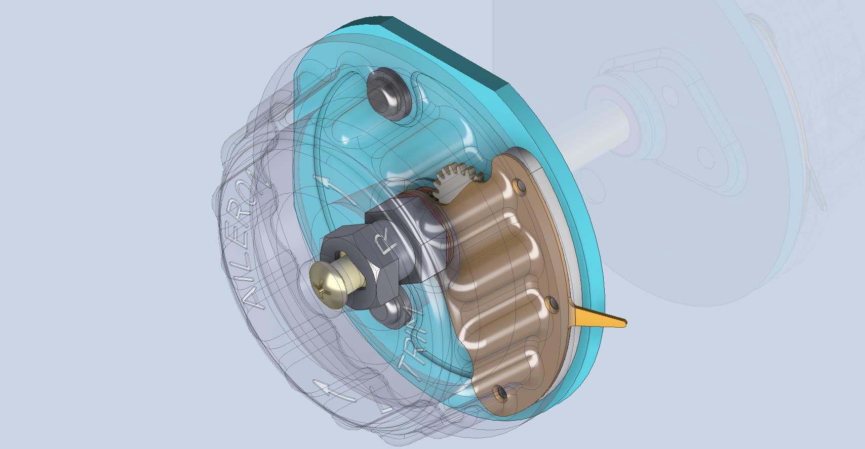
The above model is the FM2 Elevator Trim tab control, the main body of which is typical for the Aileron and Rudder on Grumman drawing 13690. The Grumman Goose has similar controls shown on the Grumman Drawing 13693. Shared components across the various aircraft are listed on the Grumman FM2 drawings.
This Trim Tab control for the FM2 is probably the most complex I have studied so far…requiring very fine manufacturing tolerances. I am not entirely sure yet how this works as there is a complex array of tabbed washers that act as stops for the dial in both directions; it is unclear at this stage how they should be configured…I will get it worked out in due course.
A lot of work to do on these projects which will definitely keep me busy through 2025.