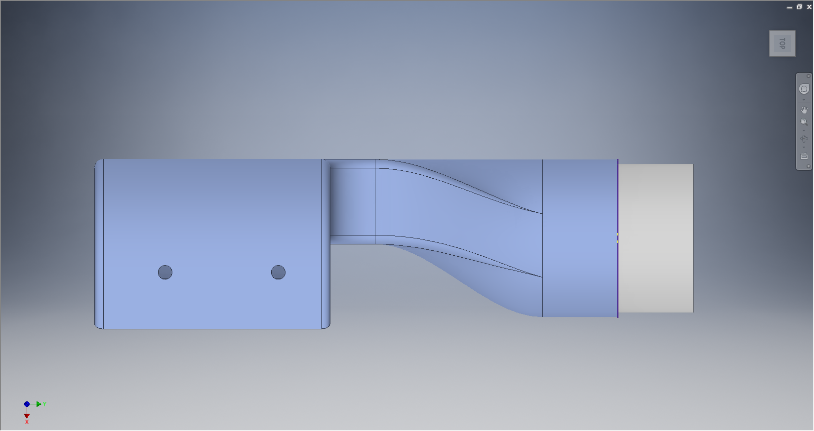
NAA P-51B/C/D Mustang: Radiator Coolant Mount
I discussed in my last post the development of a comprehensive drawing register for the P-51 and my rather ambitious intent to derive the list of parts associated with each sub assembly and main assemblies.
This could indeed be quite a task as for example on the P-51C alone we have 348 assemblies listed, some are sub assemblies and some are top level assemblies. The challenge is organizing the drawing parts list according to their assembly and retain the order of links on my filing system as per the main document register.
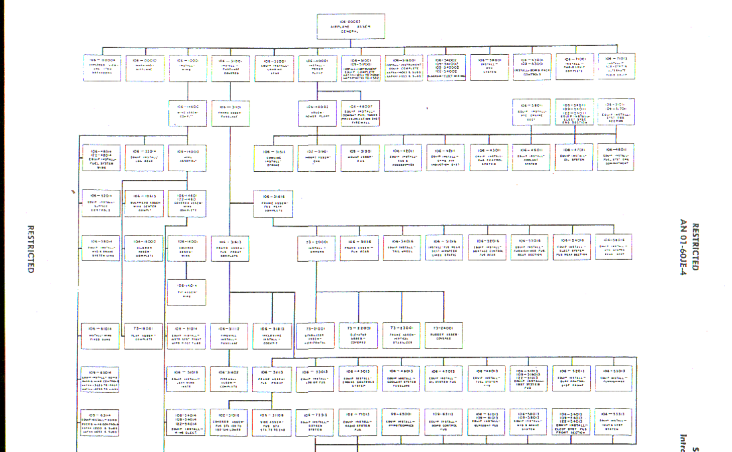 The NAA Numerical part lists (AN01-60JE-4 Section 2) give us some idea of how this data can be collated but the chart lists the top level assemblies and does not follow the hierarchy to the individual part. The individual parts though are listed in subsequent chapters of the parts list.
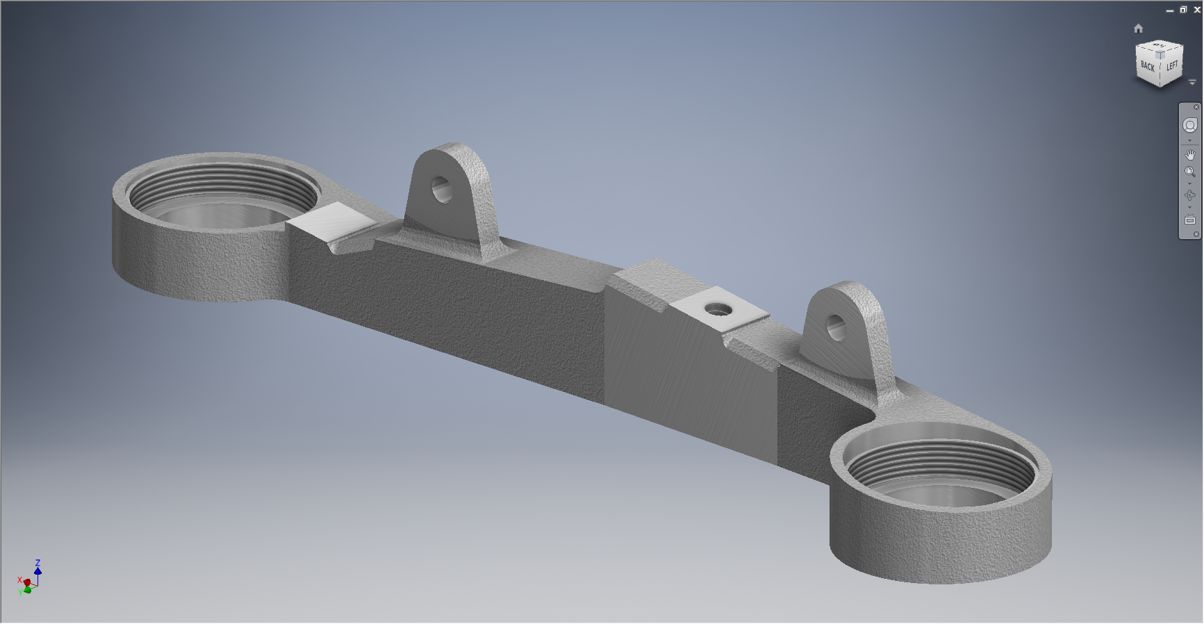
The part files themselves also contain information to assist with establishing the hierarchy of assembly; similar to the following for the Radiator Coolant Mount.
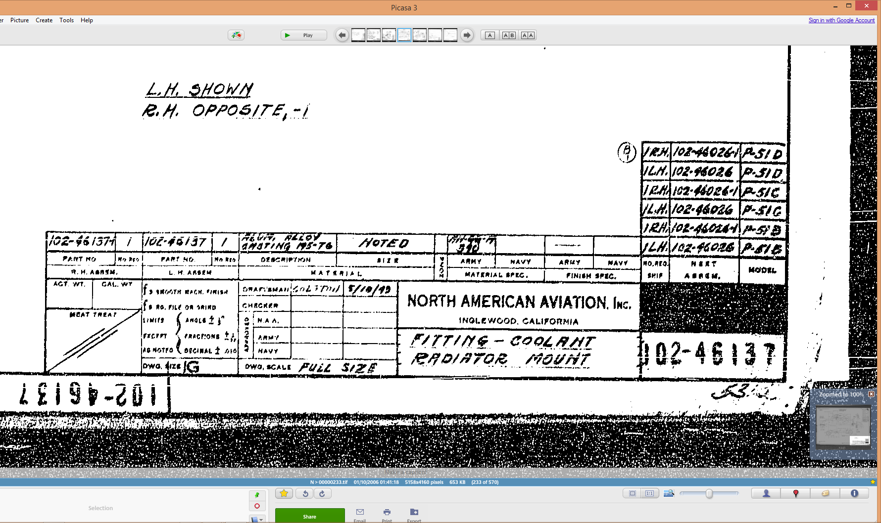
As you can see from the scans this part drawing typically lists the associated next level assembly, quantity and the aircraft variants to which they belong.
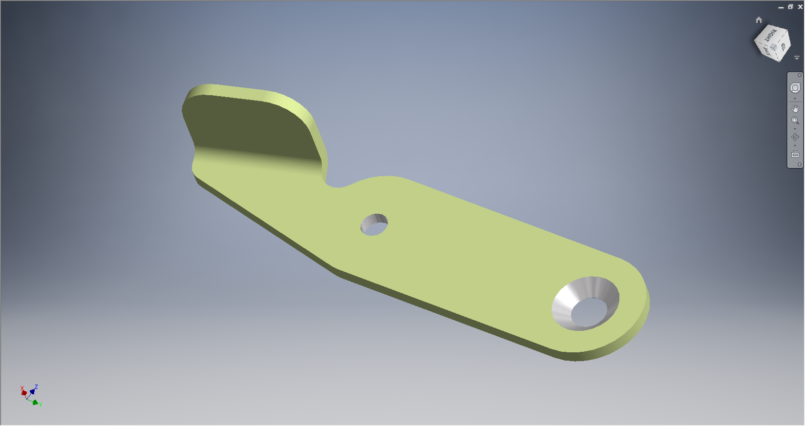
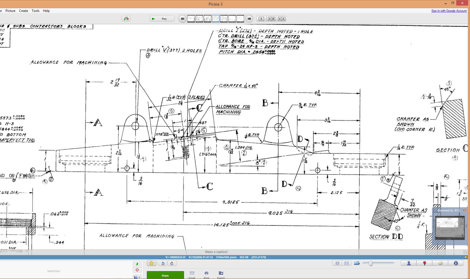
 This image on the left is the next level assembly (sub assembly) which shows the inclusion of fittings and bushings and again lists another next level assembly.
Typically this is how the hierarchy works and its great that we can track the target assembly from the individual part drawings.
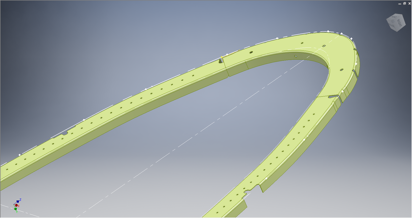
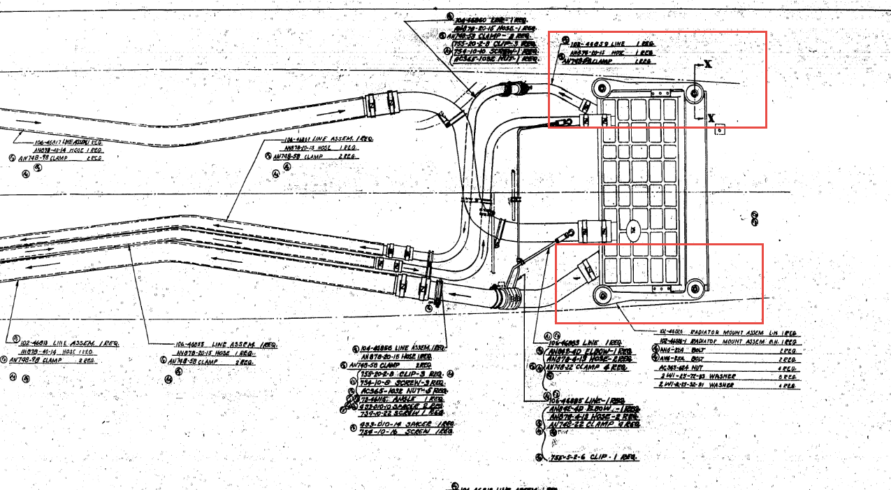 This is the top level assembly as noted in the above drawing. Our Coolant Radiator Mounts are highlighted in red.
In this example we don’t have all the drawings for the parts listed and though it would seem unlikely to be able to build this assembly with incomplete information it may be possible to interpolate sufficient data from what we know to develop the parts that are not available.
This is typical of these types of projects as the majority of scan drawing sets are incomplete and many parts can only be developed from physical examples or interpolated where we have the requisite data from other sources.
This approach is similar to how I plan to tackle this document register in identifying the links between the part files and the assemblies. We have the NAA register; which is a great starting point; and the part and assembly files themselves. There may be instances where the information from the drawings or the NAA register is unclear, in which case I would refer to other drawings in the series that may reference this information in the notes or comments.
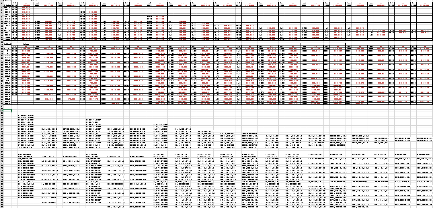
 At this stage I have transposed the NAA register assembly chart (noted above) into a spreadsheet format so that I can add additional key information.
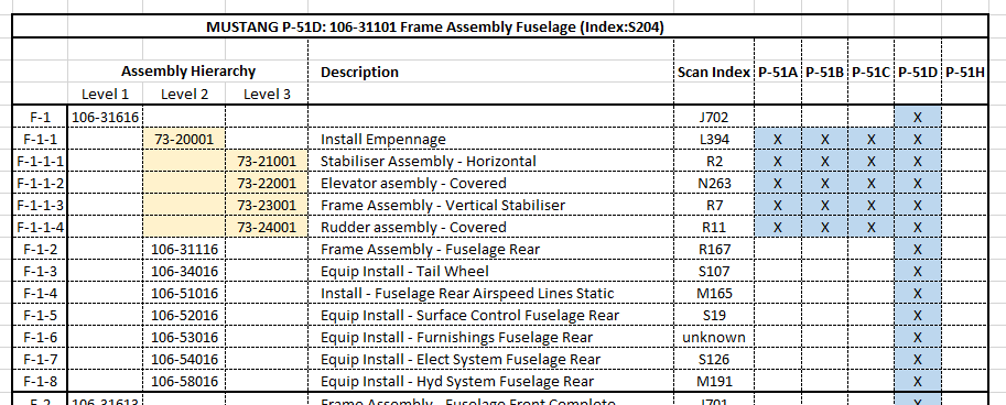
The image shown here is a partial screenshot of how the fuselage data has been organised, showing the hierarchy level of the main assemblies according to their respective position in the NAA chart.
The first column is a reference number I use for hierarchical lists of this nature. There is still a lot of work to be done to collate the parts associated with these assemblies; hopefully most of which I will be able to transpose from the NAA scanned register.
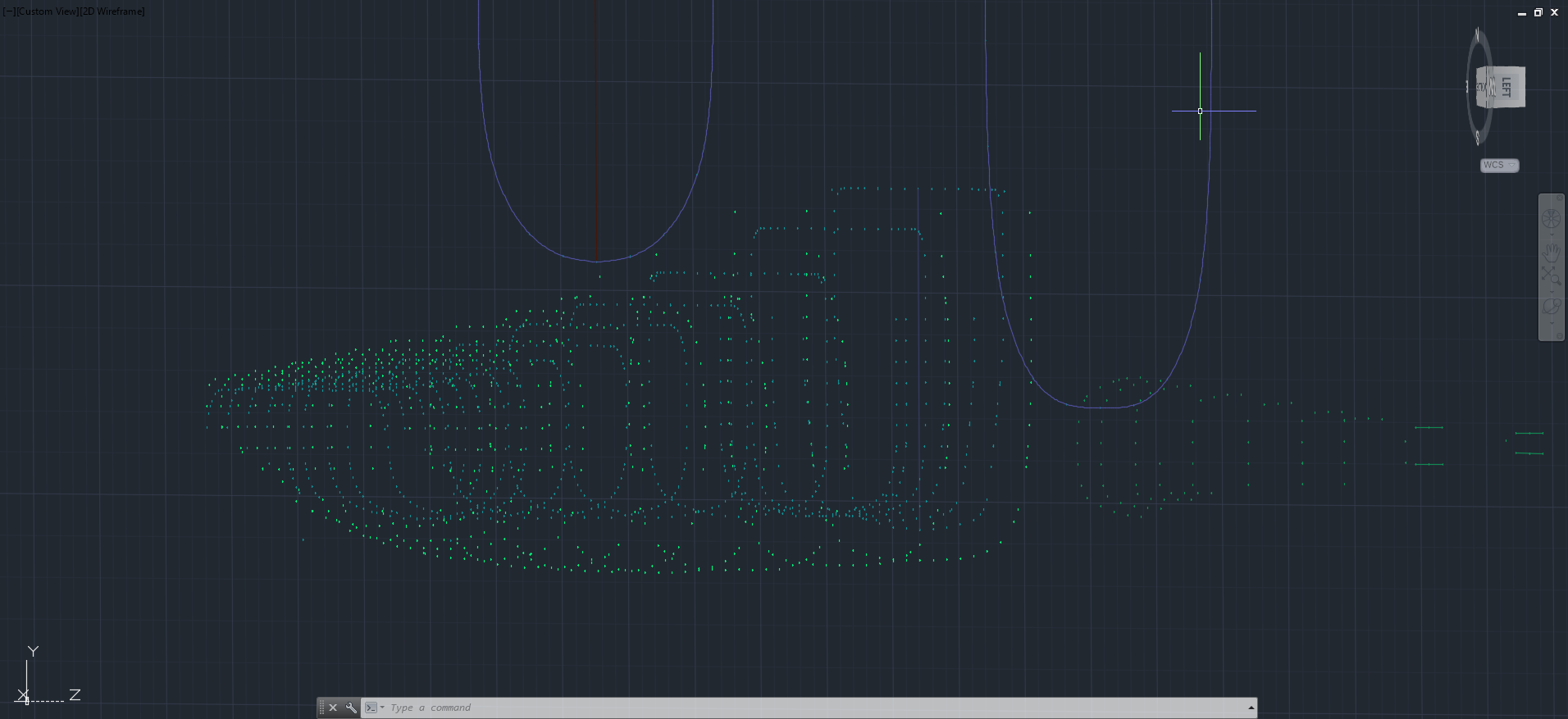
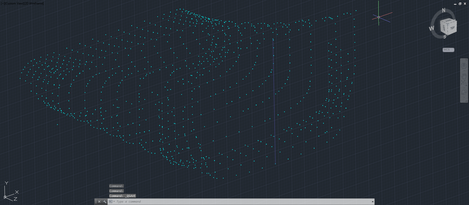
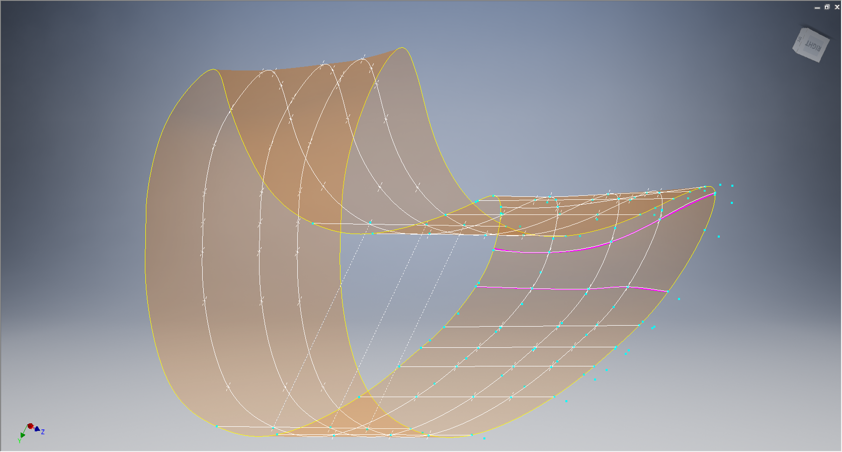
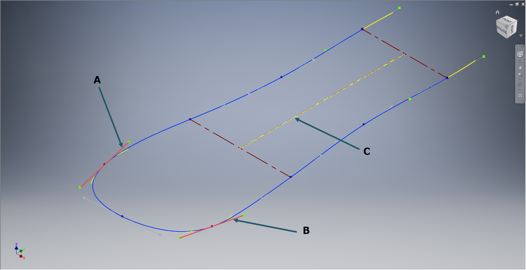
In the interim I shall continue to develop some of these part drawings into accurate 3d cad models.


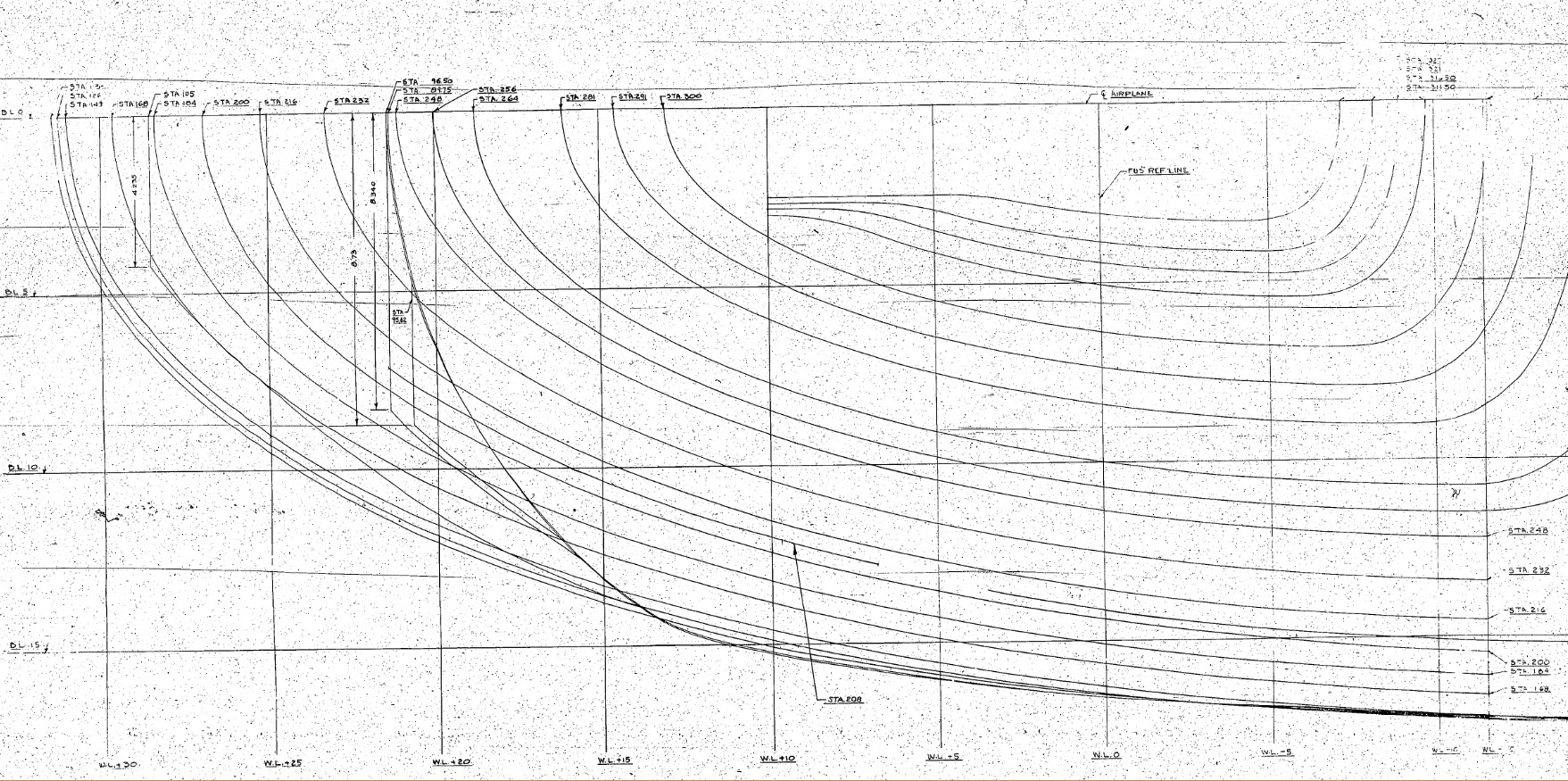

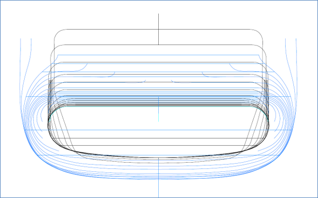
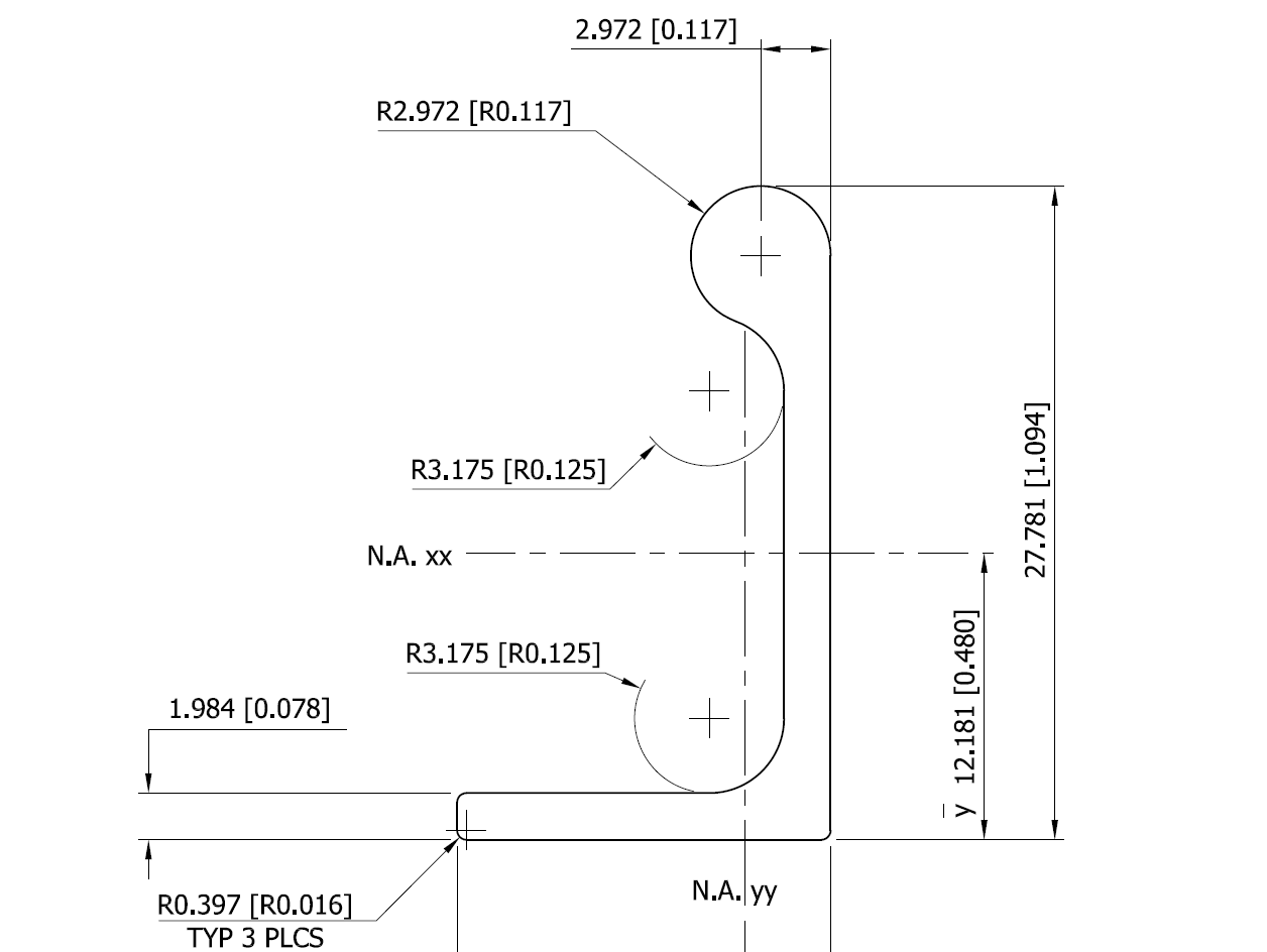
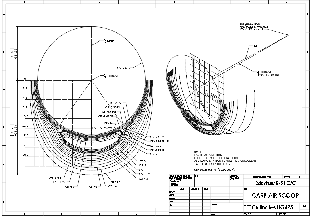
 This is a scrap view of the original NAA drawings showing the main ordinates for the Air Scoop.