Grumman F4F Wildcat: Wing Ribs:

Grumman F4F Wildcat: Wing Ribs:

Recently I received an email asking if I had done any work with the Grumman F4F Wildcat. As I do have an archive for this aircraft it was indeed on my to-do list. This inquiry prompted me to have a closer look at the archive to see what information was available to derive a working ordinate dataset.

F4F Wildcat

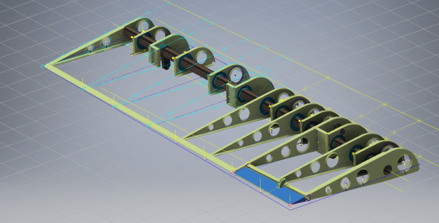
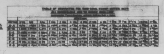
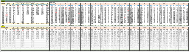
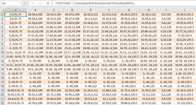
Similar to the P-39 the archive does not contain tabulated data but the part drawings do have the ordinate dimensions. Working to derive an ordinate dataset from part drawings as you can imagine is quite intensive work as you first have to collate the drawings and then develop the profiles in CAD and then extract the point data to a spreadsheet. A complete reversal of the normal process.

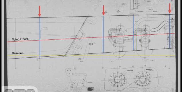
The work I was doing for the F6F Hellcat previously was not a priority task so I decided to do some development on the F4F Wildcat, starting with the wings. This threw up a few surprises as the wing rib dimensions were not relative to the wing chord as you would normally expect, instead, they were from a Base datum line. I had not seen this before and it transpires that the reason for this is because the wing ribs are actually not perpendicular to the wing chord. They are in fact perpendicular to wing datum line.

F4F Wing Ribs

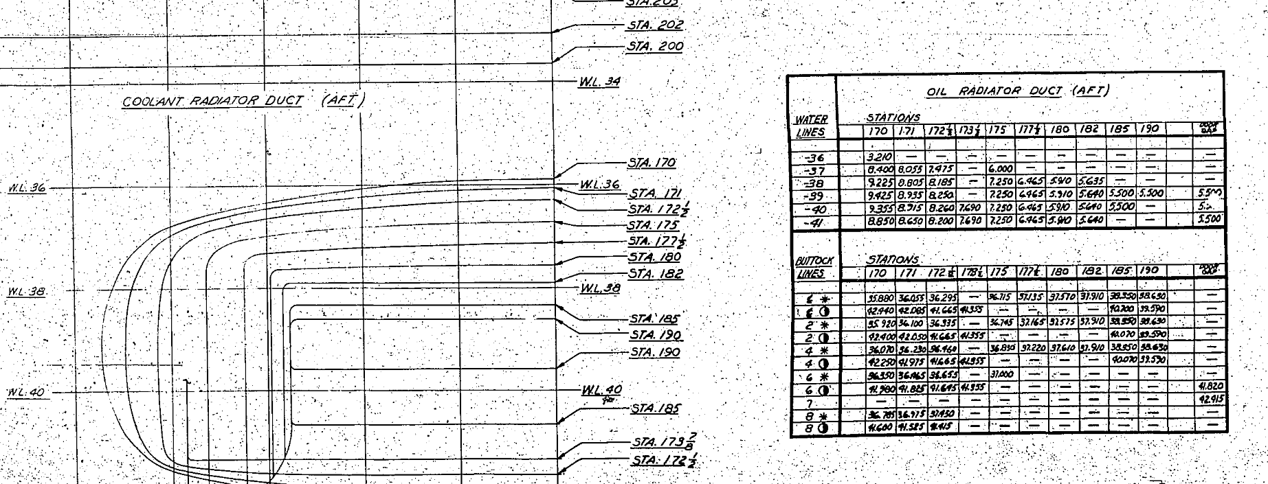
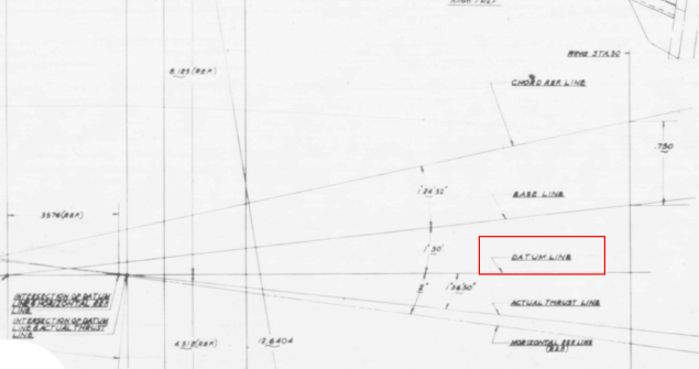
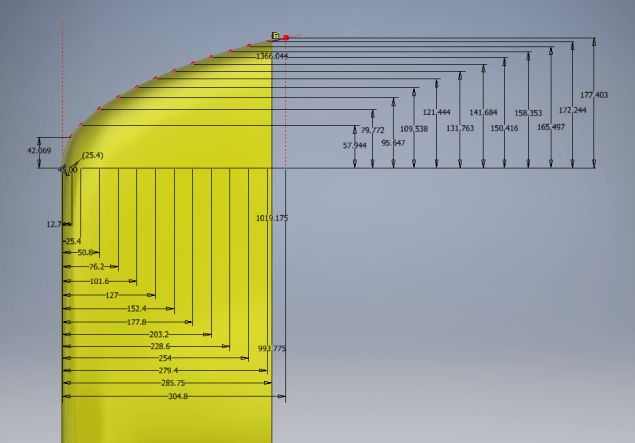
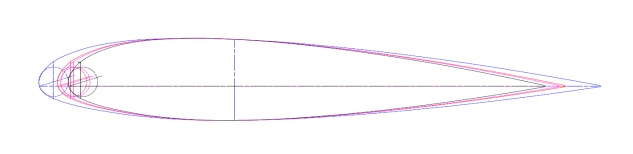
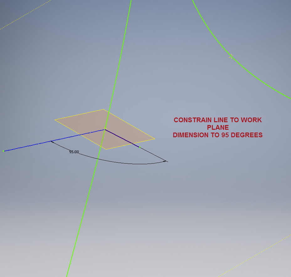
This next image shows a simplified sketch of how the dimensions are shown on the Grumman drawings. Note also that the vertical divisions are dimensions fore and aft of the “0” line (which I take to be the vertical datum) and not percentage breakdown of the cord length as expected.

F4F Wing Ribs2

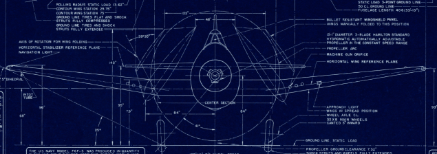
This raises all sorts of questions as to why Grumman designed the wing structure in this manner. I cannot think of any performance or manufacturing benefit in doing so. You can also see in this scrap view from an actual Grumman drawing how the dimensions are to the baseline and not the chord line.

F4F Wing Ribs3

I posted a similar question on the WW2 Aircraft forum, so hopefully, someone will enlighten me on this unusual design feature.

Update: Solved!

The wing ribs are perpendicular to the Wing Datum line, which is 1.6 degrees from the Thrust Line (essentially the design horizontal axis) that aligns with the fuselage Thrust Line. It transpires that the various wing components are dimensioned relative to any one of 5 different datums depending on their function.

2018-09-16_01-23-03

Update Sept 2018: Work in Progress:

F4F Aileron 2

2018-10-06_19-18-41

Grumman F6F Hellcat: Cowl Ordinates

Grumman F6F Hellcat: Cowl Ordinates:

I may have been a tad over-optimistic in my previous article on the F6F ordinates when I mentioned there was a good chance the Grumman ordinate data would be complete. The one exception is the cowl, although there is an ordinate drawing for the cowl the table itself is just a black blob, completely illegible. However, I checked the part drawings that make up the cowl which is quite well detailed so I made a start on the nose spinner ring.

The spinner ring main model is fine and here it is derived into the air scoop construction model. The construction requires numerous contour lines as each ordinate needs to be manually checked due to the poor quality of the original Grumman drawing scan.

Cowl nose ring3

This ordinate drawing is not deliberately blurred by me, this is how it actually looks like. The main dimension is almost legible just the fractions that are problematic. The process will require evaluating each contour line and curvature check, both horizontal and vertical as shown in the above image.

I am hopeful of achieving a good result with this model which will probably take a few days to complete.

Update 27th August:

F6F Cowl Nose Ring2

I have now determined the correct ordinates for each of the seven profiles. Notice the lower profiles have been artificially extended to the center ring, which will give me better results when lofting. After lofting a surface the plan then is to remove the mouth of the air scoop (blue) and apply the finishing flange to the inner edge.

F6F Cowl Nose Ring80

The ordinates are recorded in a spreadsheet with the x,y,z coordinates extrapolated as I previously did for the wings and fuselage.

Update: 12 Sept 2018:

Cowl Ring Cowl Nose setout dimensions verified.

F6F Ring Cowl Nose

Ordinate Dataset Completed: Wings, Fuselage and Front Air Scoop.

The F6F archive of scanned Grumman documents comprises over 7000 drawings in PDF.

Grumman F6F Hellcat: Wing Ordinates

Grumman F6F Hellcat: Wing Ordinates

I wrote an earlier article on my work with the F6F fuselage ordinates which I have recently updated. Whilst revisiting the archive I also came across the Grumman wing ordinate drawings and decided to develop those as well. I was reluctant to do this as the original drawings were not that great.

Thankfully it was not as bad as I first suspected, though it has taken me over 7 hours to painstakingly enter each ordinate manually to tabulate the ordinates in Excel.

F6F Wings

I still have to interpolate the data to generate the appropriate X, Y, Z coordinates; set out from the 35% chord; which I will endeavor to do over the next few days.

F6F wings 2

To verify the ordinate dimensions the following equations are applied. The chord length is for any wing chord whilst the LER is only applicable from station 75 to station 252.

f6f calcs2

To be honest the F6F Hellcat was not even on my to-do-list but a conversation with a colleague about the F6F performance characteristics prompted me to have a closer look at the archive. Surprisingly it is very possible that this archive may have sufficient information to generate an entire aircraft ordinate set, which is quite rare.

f6f

I will update this post when the wing model is complete, so come back soon.

Update August 23:


I have checked the Centre section profile for accuracy and noticed one point out of alignment by 2mm towards the leading edge. Removing this point allowed the natural curvature of the spline to define an acceptable profile as shown. The curvature check shows that this curve now matches the Leading Edge Radius.

The trailing edge extends beyond the 100% Chord by 5/8th inch on the centre section (Station 0) which tapers to zero at Station 252. Drawing a straight line segment from the Trailing Edge Radius results in perfect alignment with the spline.

Centre Section Stations:

f6f ctr section

Outer Panel Stations:

F6F outer wing

It is not unusual to have a few rogue points from the tabulated ordinate data which is why it is important for a detailed analysis like this.

And here, at last, the complete wing assembly:

f6f wing assembly

Vought F4U Corsair: Ordinate Data

Vought F4U Corsair: Ordinate Data;

About 6 months ago I received an ordinate dataset from a good friend Gary Henry for information purposes. It is a very comprehensive set for the fuselage comprising over 2800 points to define in excess of 1930 individual ordinates.

Vought_F4U_Corsair_(USMC)

I have recently updated my data processing procedure utilizing new features in MS Excel particularly the “TEXTJOIN” command which makes it a lot easier to extrapolate the X,Y,Z ordinates from large datasets. This dataset was ideal to work with the new process.

F4U Corsair Ordinates

The Textjoin function allows you to predefine a delimiter and then select either an array of data or individual cells using the Control/Mouse combination. You can see I have locked in the selected column and the top row. The units shown are inches but can easily be converted to millimeters.

F4U Corsair RevB

Due to the nature of the dataset, there is a very distinct central plane on the zero vertical plane, which of course I would filter out if I decided to progress this further as a CAD model. I don’t have enough of the manufacturers’ original drawings to develop this aircraft at this time but it sure is interesting working with other datasets.

F4u-1 sideview

The dataset is actually very good only 3 points not quite in alignment. I profiled the top and bottom contours and the contours either side of the fuselage centerline; all 4 curvatures were very smooth.

Update Oct 2018:

Recently received some new data that has allowed me to progress this project with the development of the Cabin ordinates as shown below.

F4U Cabin

F4U Corsair2

NAA P-51D Mustang: Wing Ordinate Rev

NAA P-51D & B/C Mustang: Wing Ordinate Major Update:

Thanks to Roland Hallam, I am now in receipt of new verifiable information that has prompted a return to the P51 project and a major update to the wing ordinate data sheets.

2017-05-21_15-46-57

Many of the blanks have now been filled in and new additional information added. The above image is a snapshot of the work in progress. The groups highlighted in blue are checked verified dimensions, the red values are those that have changed and those areas remaining in white have prompted an interesting conclusion. Up until now, it was presumed that the wing profiles for the P51D and P51C were the same with the exception of the wing root, however, closer inspection would now suggest that a few rib locations are also slightly different which requires further investigation.

I am still working through the new information and dissecting what is relevant to the P-51D and the P-51B/C variants. This will probably take me a while to evaluate but I am confident that this will result in the most comprehensive dataset yet compiled for the P-51 wings.

I had not expected to return to the P51 project at this time but I’m sure you will agree this is an exciting development.

Bell P-39: Cockpit Glass

Bell P-39: Modelling Curved Cockpit Glass (Inv 2017)

Modelling the Cockpit glass can be a challenge to achieve the correct curvature and create the inevitable jogged and profiled edges.

P-39 canopy

The Bell drawing lists all the ordinates to enable us to create the profile sketches from which to derive the required basic shape with two areas worth extra consideration in respect to the rounded corners and the jog along the perimeter edge.

We developed the initial extruded surface from the contour ordinates and then simply extruded a sketch to trim this surface to the basic shape.

P-39 c1

The first thing we need to do is to fillet the corners. In Autodesk Inventor we cannot fillet a single surface, though we could use various techniques to do this we decided instead to Thicken the surface an arbitrary amount ( it does not much matter how thick it is) and then apply a fillet of each corner of the solid which ensures correct tangency.

P-39 C2

The jog along the edges is a bit tricky, given the nature of the surface. One way of doing this would be to sketch the jog profile and sweep the profile using the edge as the path. We tried this in several configurations but the result was not consistent.

To solve this we need to consider what a solid comprises off in order to rethink our strategy. A solid is essentially a series of closed surfaces that are used to contain the solid properties. With this in mind, we started by offsetting the top surface to create a copy at the desired jog dimension inward. Along the edge of this new surface, we sketched a circle with a radius the same as the jog flat dimension and swept this along the perimeter of the new surface.

P-39 C20

By using a circle profile for the sweep we ensure that the resulting flange; which is trimmed from the copied surface; will be a consistent width throughout its length. Now we have a surface representing the exact dimensions of the jogged top face at 3/8 inch. We do something similar for the top surface which is selected from the solid with the circle set to a bigger dimension to facilitate the jog transition curves. This time simply trimming to remove the edge width.

p-39 c21

This gives us 2 surfaces, the lower surface for the top face of the jogged flange and the second, the actual main surface for the top of the canopy glass. To fill the resulting gap between the surfaces we used a patch surface.

P-39 CX

We have trimmed the surfaces of the solid body thus breaking the solid cohesion leaving a number of orphaned surfaces which can now be deleted. To finish we would stitch the surfaces and then thicken to the required amount.

p-39 c12

To achieve a smooth transition when applying a patched surface between 2 surfaces a good result can often be achieved by using the tangency option relative to each joining surface. In this particular instance, the patch size was too small to do this so instead we applied fillets to achieve the same results.

A Note on Curvature:

P-39 Canopyx

It is absolutely critical to manage the curvature of the sketch profiles prior to lofting to ensure the best possible surface. This usually requires marginal adjustment to the ordinate dimensions; generally fractions of a millimetre; to achieve a good result.There is a small shoulder on this glass panel thus accounting for the slight edge deviation. To improve further the definition of the finished surface we can convert to a freeform surface which will derive a new surface with G2 curvature.

P-39 Cockpit Glass

Another Quick Tip:

Sheet metal flanges are restricted in Inventor to straight edge segments whereas with Solidworks we can actually create a curved flange where there is continuous tangency. One workaround in Inventor is to sweep a profile along the edge of the sheet metal part to create a flange or alternatively use the Ruled Surface feature.

P-39-1

This feature provides a few functions for extending surfaces either perpendicular or tangential to an existing surface. In this example, we simply select the default and create a perpendicular edge without requiring additional sketches.

Thicken the resulting surface, convert to sheet metal part and apply a traditional flange!

Bell P-39: Creating Wing Fillets

.Technote: Bell P-39 Creating Wing Fillets.(Inventor 2017)

Wing fillets are probably one of the most complex aircraft items to model as they need to follow the curvature of both the wings and the fuselage shell. Invariably we have many offsets to contend with and variation in angular alignment of the flanges.

The following images are typical of the manufacturers drawings with an ordinate table listing the X,Y ordinates and angle of the flange at each point.

As usual we would start with marking out what we know; in this case the ordinates points from which we create the reference geometry.

P-39 Wing Fillet1

The reference geometry in this example is the 2 splines for the flanges connecting to the fuselage (left) and the wing (right) with a horizontal base line for the lower flange.

We then check the curvature of the splines to ensure we do not have negative curvature; adjusting the handles to negate this where necessary.

These Fillets are full of tangent and perpendicular dimensional oddities that can sometimes be a real pain to achieve satisfactory results .

Previously we would create a work plane (tangent) at each node and individually sketch the required flange construction lines set to the correct angular value. This was a lot of work and a heck of a lot of sketching. Thankfully Autodesk have introduced some nice functionality to the 3D sketch environment in Inventor 2017 making this task so much easier with provision of logical constraining options and associations.2016-08-14_15-19-34

In Inventor we have various planar constraining options as shown. The top one is to constrain a sketch element to a surface and the lower ones are parallel constrain options to the main work planes.

We would still create the work planes tangent to each point as before; I have shown one for clarity, then we simply move straight into the 3D sketch environment to model all the flange construction lines.

We first need a reference base line constrained to the tangent spline work plane and also be parallel to the main work plane YZ.

P-39 wing fillet 3

We then sketch the flange line, constrain to the tangent spline work plane and dimension to the reference line as shown at 95 degrees.

P-39 WING FILLET 5

It really is a simple case of drawing a few lines and just using the planar constraint options to ensure correct tangency for developing the flange guide lines. Furthermore you don’t even need to project geometry from the 2d sketch as you place the line it will automatically connect to a point on the 2d sketch.

We continue doing this for all the ordinate points as shown then surface loft the flanges and apply a surface patch to create the main body. I should note that the surfaces shown have already been trimmed to the extents of the part.

It is very tempting at this stage to stitch and then thicken to achieve the finished part, however in my experience occasionally the transition of sharp corners introduces anomalies along the edges which can be negated if we first apply a fillet prior to thickening.

P-39 Wing Fillet2

To finish the part after thickening, I converted to a sheet metal part and added a flange to the base at 7.5 degrees, a few holes and that’s it done. There are some flange holes still to be modelled which will be done later when the other connecting parts are modelled and checked for alignment in the assembly.

Progress Update:

The following image shows a typical interface check between the P-39 wing and fuselage:

P-39 Wing Location

…and here the Radiator Intake Duct, preliminary alignment:

P-39 Rad Intake Duct

This radiator intake duct was an interesting development as the Bell chaps had provided both the tangential and the exterior dimensions at 2-inch intervals; on plan and elevation; which collectively are projected to form the profiles at each station. The white sketch at the bottom of the image shows these dimensions on the side elevation, with the curved lines depicting the tangent lines. I checked the curvature of this line and I only needed to adjust 2 dimensions by a minuscule amount to correct for negative curvature.

Update July 2022: New Revised P-39 Ordinate/CAD Dataset:

For all inquires please get in touch: hughtechnotes@gmail.com

Bell P-39 Airacobra: Fuselage

Bell P-39 Airacobra: Fuselage

This is an update on the P-39 project. I have actually been drifting between this and the P-51 Mustang as a number of inquiries have come in regarding the ordinates and various questions on the Oil Cooler model and landing gear mechanisms; which has been an interesting diversion.

Getting back on topic, I thought it may be prudent to write a quick update on what I am doing with the P-39 Airacobra and where I hope the journey will take me.

I have of course continued working on the ordinate data spreadsheet which is derived from the part drawings themselves. This serves as a check whilst I am developing the structure. The 3D models are being developed in context, i.e the individual part models are located to the 3D spatial ordinates relative to a single datum so when I plug these into the assembly they will import to the correct 3D location thus negating the requirement for constraints.

2016-08-12_22-48-54

This is the first time I have worked this way as I usually just model the part and then constrain to the corresponding items in the assembly, but this is usually dependent on the quality of the assembly scans to clearly identify and ensure correct alignment of the parts. As we all probably know these scanned files are the most likely to have problems with legibility. In many respects having the part files modelled relative to ordinates in 3D space ensures that the parts line up correctly and I don’t have to worry too much about the quality of the assembly scans.

P-39 Airacobra Fuselage

The P-39 main assembly drawings are actually not too bad as the image above shows. This is a scrap view of the fuselage Longitudinal, comprising many small parts all riveted together to form the assembly. The area in red is where I am working at the moment; which is a major node; just aft of the engine bay; where the many struts and braces overlap on both sides of the stiffener plate. The following image gives you some idea of the detail to which this is being developed.

P-39 Airacobra Fuselage1

The pilot holes for the rivets are unique to each individual part and just like the real process of construction these holes will be match drilled to all the other corresponding parts in assembly.

Modelling the complex parts and locating all those holes takes a lot of time but I believe the end result will be worthwhile. With this degree of accuracy you could just about build one of these aircraft from scratch!.

Quick Technote: P-39-01
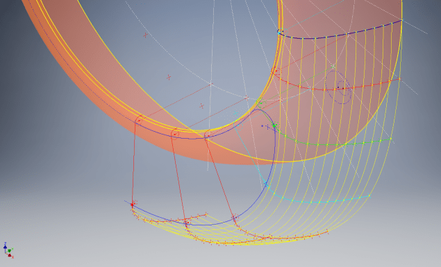
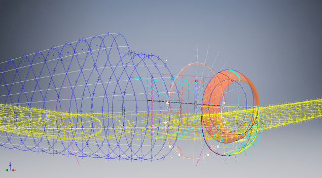
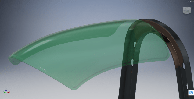
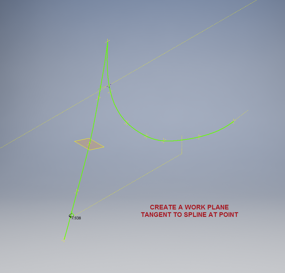
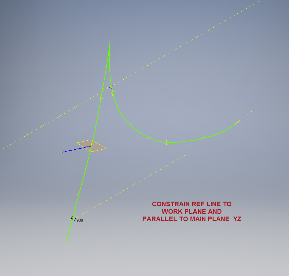
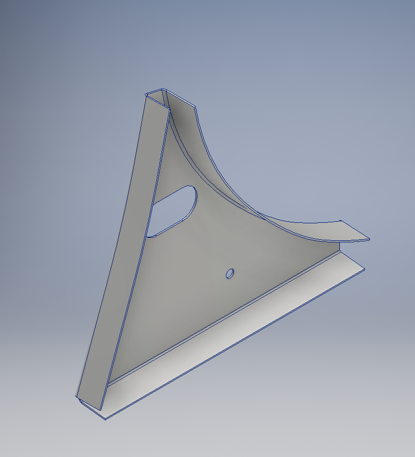
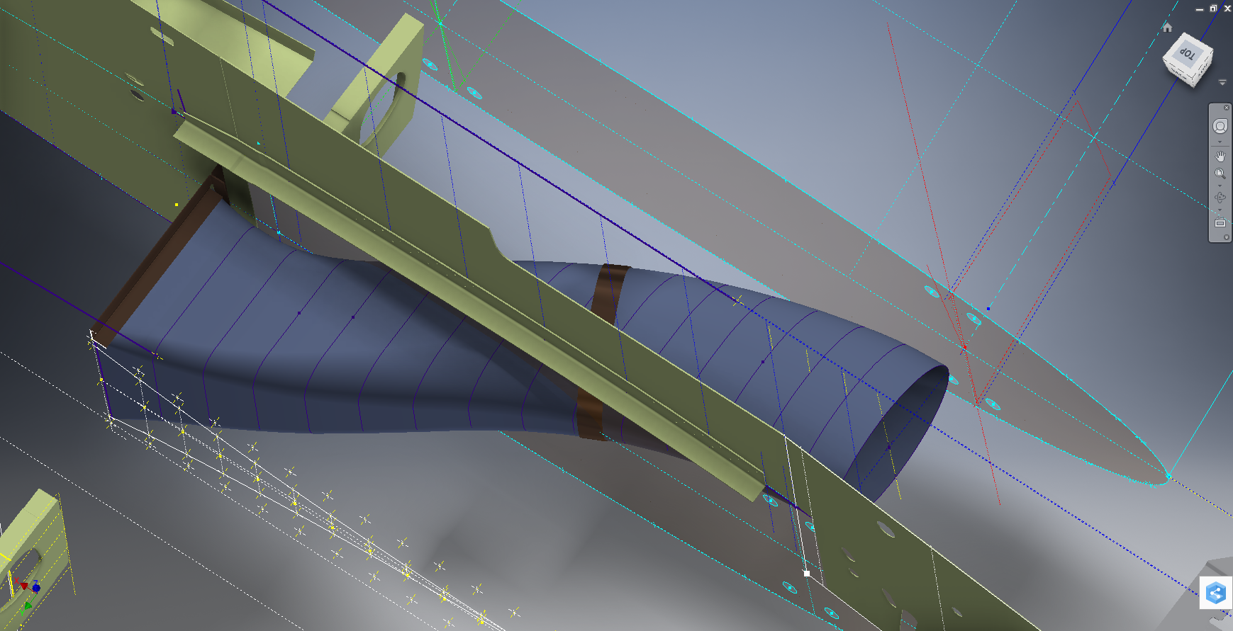
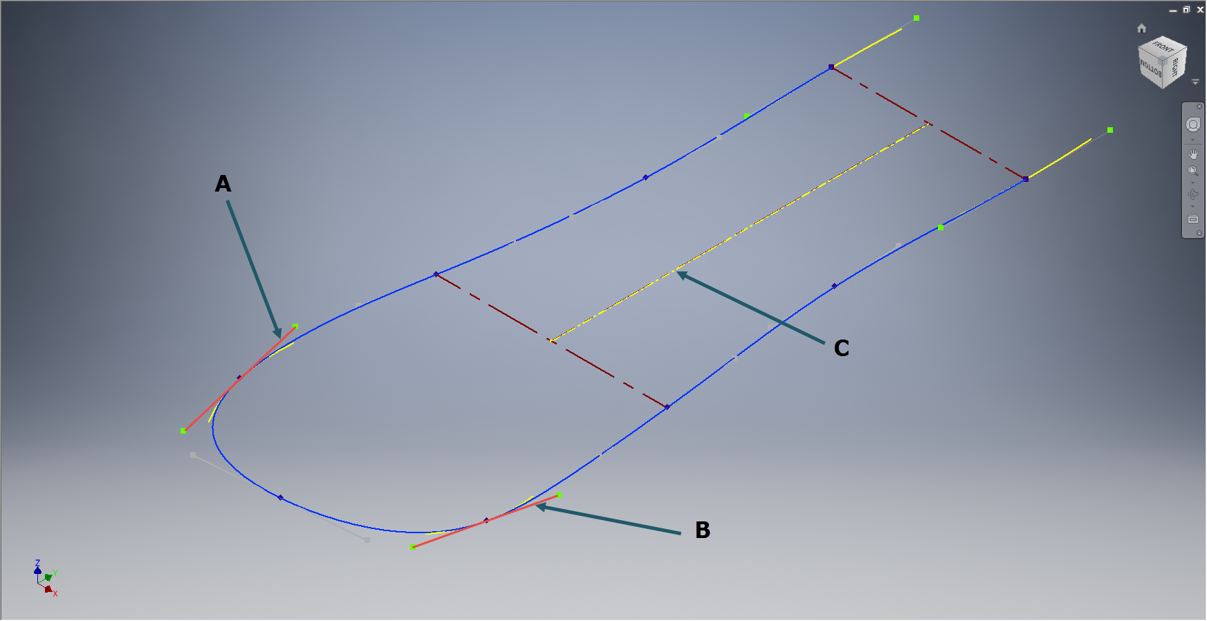
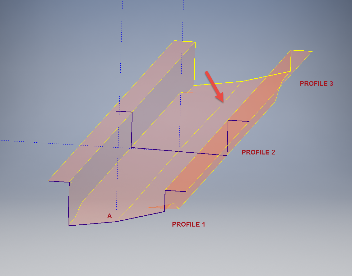
This is the lower level fuselage cross member that has a built in twist to align with the connecting frames at both ends. The model consists of 3 profiles with the 2 outer ones containing a small angular deviation in the centre at point A. Normally I would loft the profiles to create the finished surface but this projects the deviation throughout the length giving us 2 surfaces; which does not look good.

I therefore deleted the resulting 2 base surfaces and simply replaced them with a boundary surface. I’m sure you will agree the result is a much smoother gradation of curvature; that matches expectations.


Mustang P-51 B/C Ordinates

Mustang P-51 B/C and P-51 D Ordinates:

P-51BC Layout

I have had a number of requests for the ordinate spreadsheets I developed for the Mustang P-51 B/C and D fuselage, cowl, cooler and air intakes, so I have decided to make them available to all; which could save you considerable time and effort.

The ordinates are listed on 10 separate Excel workbooks with 18 spreadsheets for all known ordinates from manufacturers data. The ordinate listings are in both mm and inches with the X,Y,Z coordinates extrapolated from this data-set for ease of transferring to a suitable CAD system. The total points listed are literally thousands.

P-51 D Layout
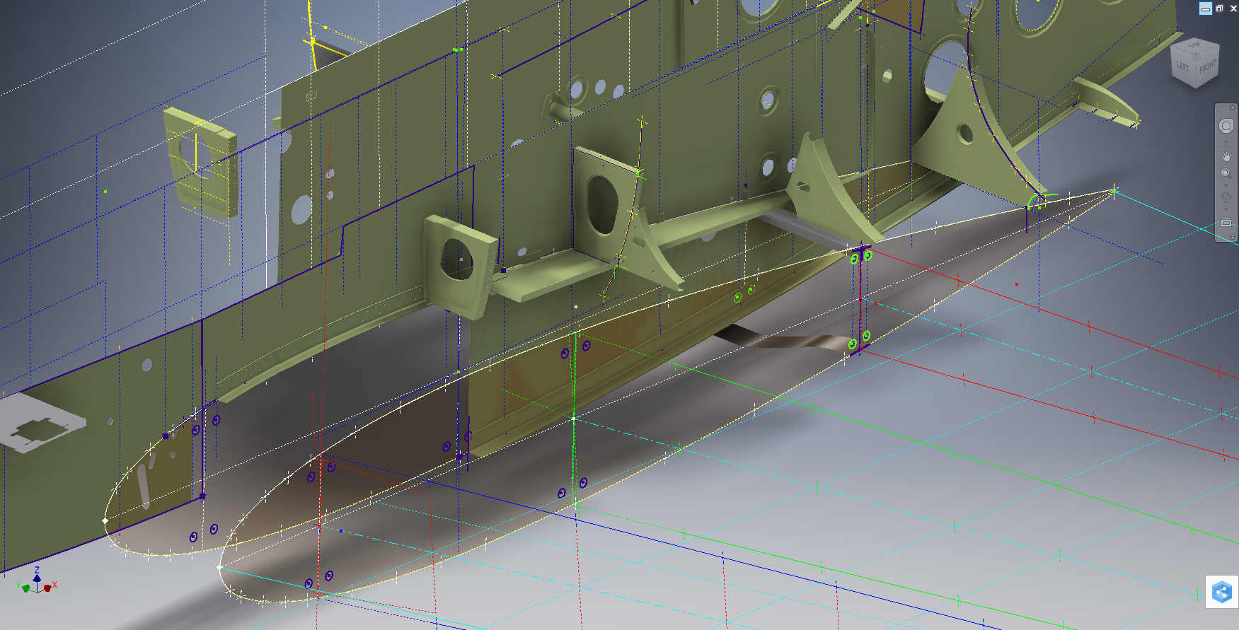
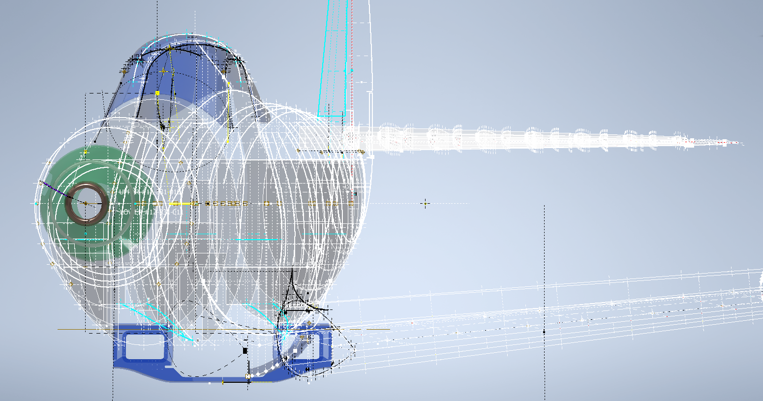
102-00005: Fuselage (BC main)
102-00006: Fuselage (forward to cowl)
102-00007: Removable Scoop (fuselage, Int and Ext)
102-00008: Coolant Radiator Duct (Aft Section)
102-00008: Coolant Radiator Duct (Fwd Section)
102-00008: Oil Radiator Duct (Aft)
102-00009: Carb Air Scoop (Cowl)
106-00006: Wing (P-51D)
73-00006: Wing (P-51BC)
 
+ Autocad DWG Fuselage Frame & Wing Profiles P-51 B/C and P-51D (ref only)
NAA Master Dimensions Report (wings, fuselage, landing gear).
Include scans of original source documents for reference.
 
The spreadsheets are not locked or protected so you can manipulate the core data to suit your own applications.
The P-51D fuselage profiles are reference only due to being mathematically generated based on original NAA methods and thus are not verified.

This represents a huge number of hours worked, meticulously listing each ordinate individually and then creating cad drawings to check the ordinates and derive the ordinates that are unclear on the manufacturers’ drawings.

2016-06-04_23-33-26

The ordinates for the P-51D wings comprises 2 sheets; the first listing the tabulated data as per the original manufacturer drawing and the second extrapolated to compile the X,Y,Z coordinates for input into CAD.

P-51D WING ORDINATE

P-51 Wing Profiles

Update 20 Aug 2019:

The spreadsheets now include the OLEO undercarriage and general tidy up of datasheets for consistency. Now probably the most comprehensive and complete dimensional study of the P-51 B/C and D. 2018-09-20_22-45-40

Horizontal Stabiliser and Fillet Ordinates layout:

Mustang P-51 BC

Sample data for P–51B/C and P-51D;

For further details see this more descriptive post or send me an email to HughTechnotes@gmail.com 

Autocad Inventor: Splines

Spline Technote:

Splines are an absolute necessity when developing the finished profiles from the ordinate points; which occasionally throws up some unexpected results.  Invariably at some point we need to manage the curvature of the splines in order to achieve the desired result.

2015-06-09_10-15-47

The image shown here is a screenshot from the NAA P-51 fuselage station profiles, which shows clearly the ideal curvature for each station.

This image can be overlayed in CAD to serve as an aid to achieve the correct spline curvature.

Actually manipulating the curvature of a spline needs to be done in a manner that achieves symmetrical results on both sides of the fuselage station profile.

I was working on the tail-end profiles, which were giving me grief as the ordinates points were not sufficient to achieve anything close to the curvature I needed on the lower section.

2015-06-09_13-26-35

In Inventor we have constraints for symmetry, which are normally applied when working on a sketch to ensure that changes on one side of a model are reflected exactly in the other.

Using this same technique I activated the spline curvature handles (A&B) on each of the  points I wanted to be symmetrical (about center at C) and applied the constraint accordingly to the handles (red).

2015-06-09_17-29-44Now when I adjust one side of the curve the other side automatically reflects the changes.

I should note that the majority of curves generated from the ordinate points are usually very good; requiring very small if any adjustments; so its quite practical to spend some time in the areas where they are not so good.

At some stage the profiles will be lofted as a surface which would then be analysed to verify curvature and alignments.