NAA P-51D Mustang: Project Cad Technote Multi Body Parts
The process of developing these drawings into accurate 3d models relies on maintaining the hierarchy according to the original NAA drawings, even if sometimes it gets a tad confusing when dealing with what constitutes a “sub-assembly” as I mentioned before.
The sub-assemblies I described as “Part Assemblies” as the assembly unusually comprises a fully detailed part inclusive of additional items like bearing, spacers etc.
I have reviewed my approach to how I deal with this and thought it may be prudent to write a quick note on this technique.
I am utilising the multi-part feature within Inventor for this, which allows you to model separate solid parts within a single part file and then create an assembly that comprises some or all of these solids.

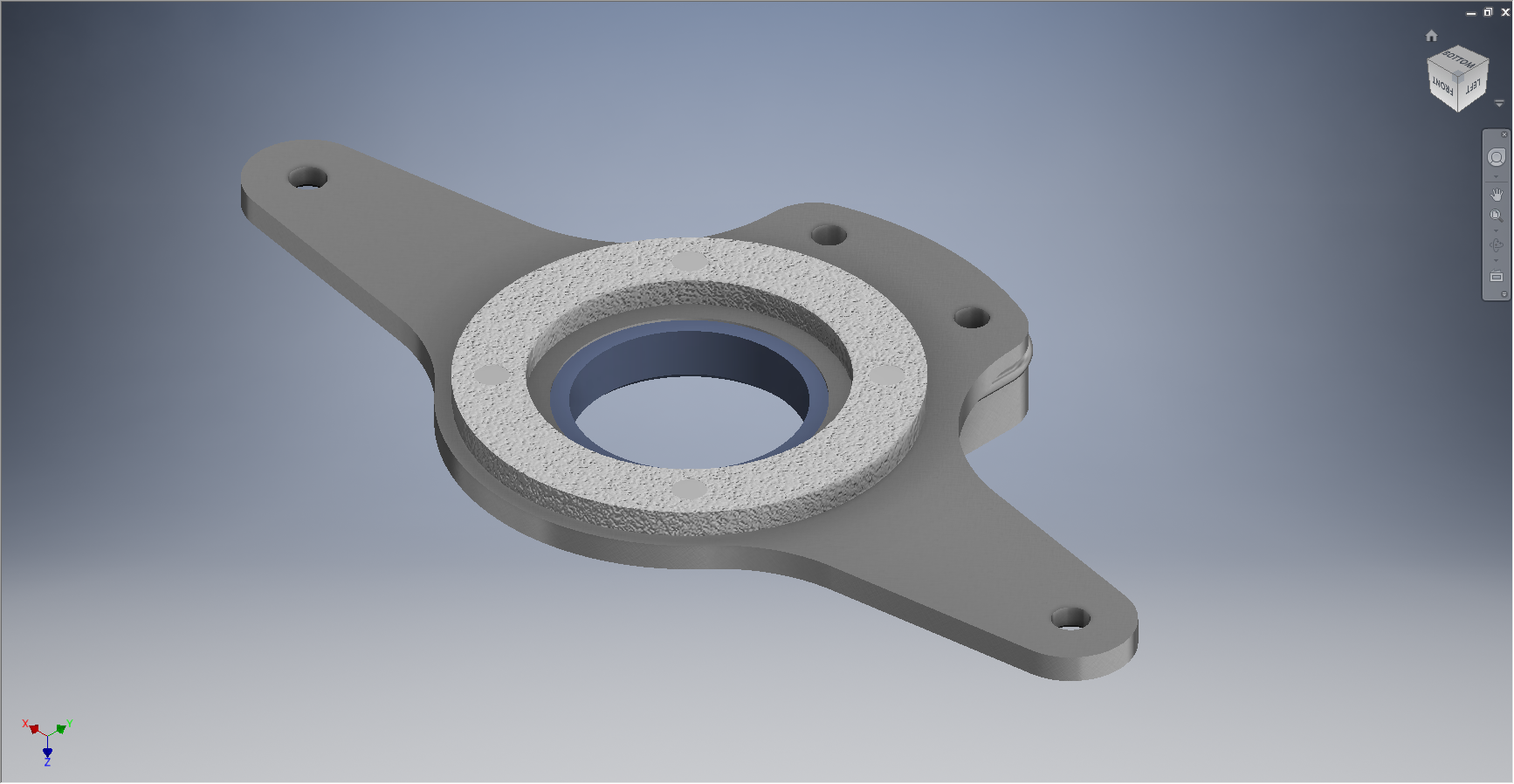
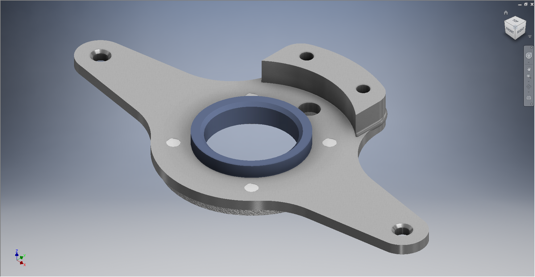
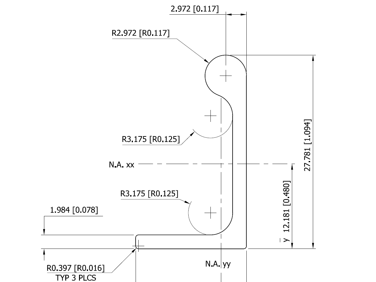
This is a scrap view from the NAA drawing showing an assembly that has 2 configurations based on varying paired angles with spacers and rivets as shown.
Each of these items has a suffix added to the part number i.e -1, -2, -3 etc.
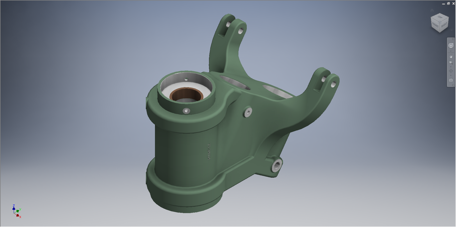
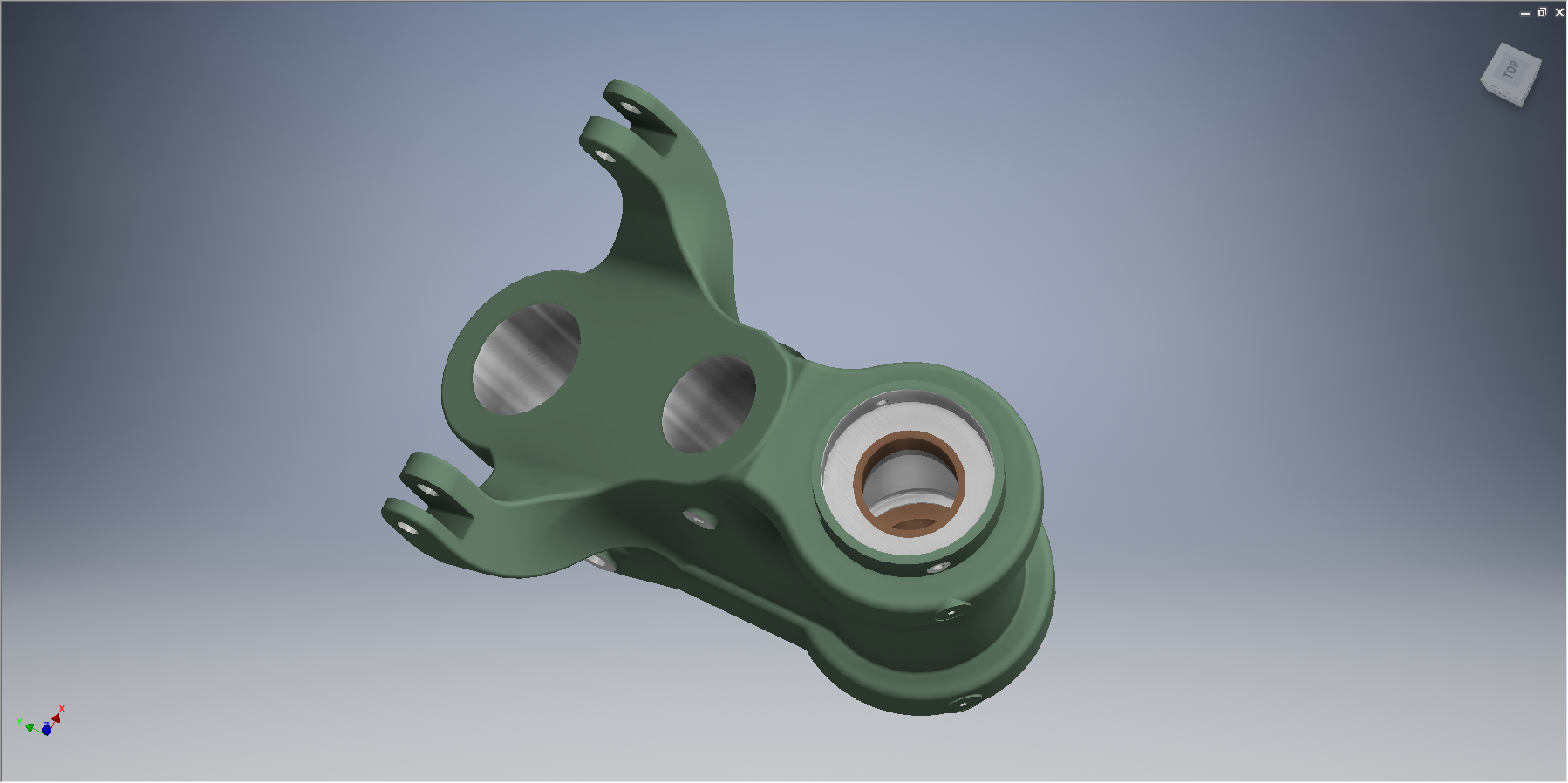
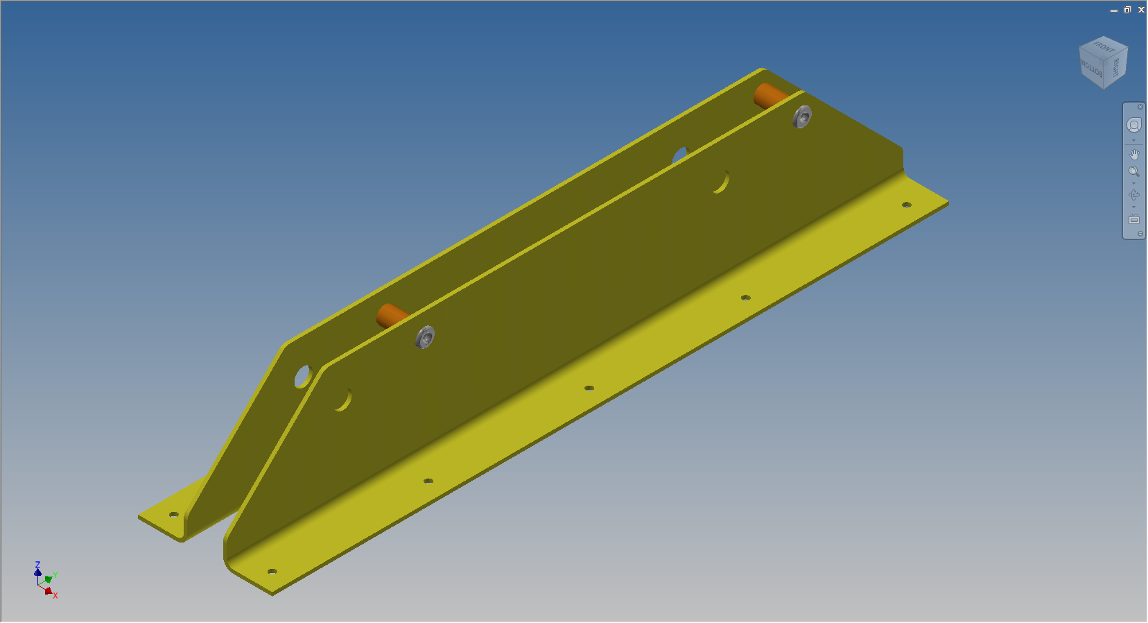
These images give you some idea of how I have modeled this, with the first image showing the configuration of items 2 & 3 and the second showing the configuration of item 2 & 4; all in one cad part file.

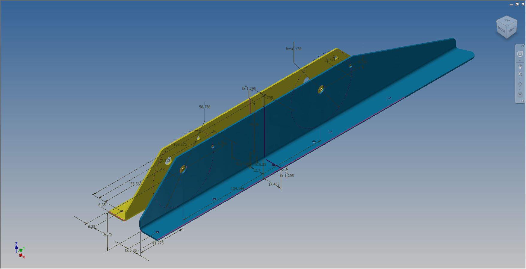
The beauty of working with multi body parts is that you only need one set of sketches that can be shared between all 3 parts.

The sketches are dimensioned exactly as the original drawing…I mention this because I would not normally dimension from the edge of an angle section (cut edge); its not really good practice!
The image on the left shows the feature tree within Inventor; listing the 3 solids with appropriate suffixes.
The part file name (at the top) comprises the NAA drawing number with a suffix noting the archive reference.
All I have to do now is create an assembly for each of the configurations and add the relevant spacers and rivets. This is done very quickly using the “Create component” feature. The assembly number will comprise the NAA drawing number suffixed with either a -1 or a -5 respectively.
 Only assemblies created from a multi-body part will be suffixed with a numerical character, otherwise they will simply be suffixed with SA.
Using this technique we maintain the integrity of the NAA numbering system with an hierarchy that suits the CAD strategy.
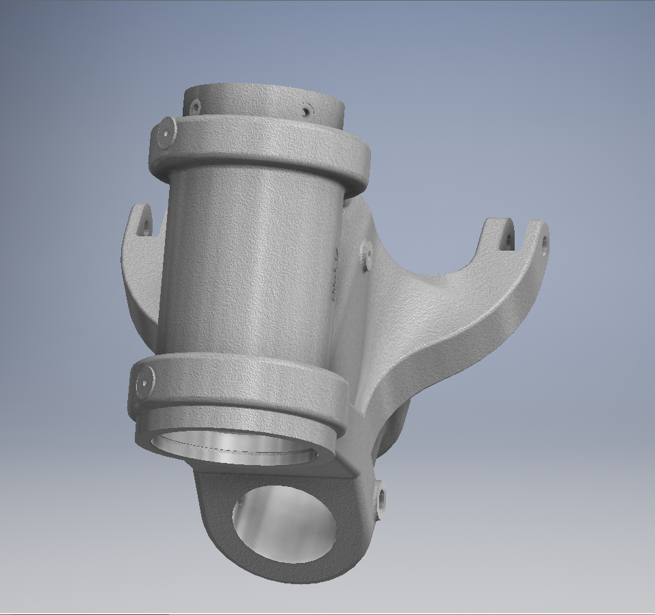
In a previous post I discussed “as-fitted” parts; like bushes; that might be press fitted and and reamed thus dimensionally different from the manufactured part, so these will still be modelled within the part file to “as-fitted” state and not brought in as a component of the sub assembly.