NAA P-51D Mustang: Landing Gear Dims

NAA P-51D Mustang: Landing Gear Dims

I am currently working on the Landing Gear geometry dimensions to check the data for accuracy. During the course of this research, I thought it may be of interest to share some Excel formula for converting angles shown in Deg Min Sec to decimal degrees and vice versa.

p-51 Landing Gear

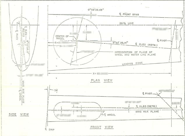
The plan angle for the OLEO Strut relative to 25% wing chord is 4° 32′ 35.14″ as shown in the above sketch which translates to 4.543094 degrees.

The accuracy of the angles and dimensions in the NAA documentation is rather good with small deviations occurring of only 0.003mm when developing this in CAD. I should note this deviation is negligible and for all intents and purposes can be ignored. However, I like to get this stuff right so I have set about developing the landing gear dimensions to be as close as possible to be exact.

As I have already developed the cad geometry I measured the same angle above from the CAD system which is now giving me 4.54309673 degrees.

In Excel:

excel table

Starting from the left; in column A; I have input the angle from the cad system, then systematically converted to Deg, Min, Sec in separate cells and then converted back to a decimal angle in column E.

The equations for each cell are as shown below:

p51 Landing gear eq

Just enter the equation in the cells denoted; so for the first equation, this would be in cell B2. The latter equation works fine without parenthesis, which I included just to keep the equation tidy.

The Landing gear geometry will be recorded in a separate spreadsheet and added to the P-51 Ordinate Package. Mustang P-51 Ordinates

P-51D LG

Technote: Icosahedron Edge Calc

Technote: Icosahedron Edge Calculation:

Geodesic geometry is rather interesting and occasionally quite challenging. I have recently been involved in a project to explore construction options for a structure based on an Icosahedron form. Although the basic geometry was created using Inventor I was curious about the underlying mathematical formulae pertaining to this type of geometry. I also like to be able to verify key dimensions in the 3d model by separate calculation.

One site I would recommend for calculating this stuff is Rechneronline which provides various options for calculating based on known criteria, an example of which I have shown below.

2017-04-20_00-36-10

The formula provided are comprehensive but lacking specifically the formula I was looking for to calculate the edge length for a given radius. The fourth formula in the list does include the value (a) which is the Edge Length and therefore can be transposed to determine the value we need.

Here I have rewritten the fourth formula with the value (a) shown as (L) for clarity.

2017-04-20_00-30-49

To determine the value (L) the transposed formula would be thus:

2017-04-20_00-31-02

This is a small snippet of information that I hope may be of some use for anyone interested in Geodesic geometry.  I should note that the 4 is a multiplication of the sum of the parenthesis and not a power to 4 superscript.

To use this in Inventor the formula can be entered as follows in the parameter dialogue box as a user parameter called “EdgeL”:

2017-04-20_02-15-02

The resulting Model value verifies the “d112” dimension from the 3d model.