Technote: Inner Workings

Technote: Inner Workings:

Working on the controls and instruments for the P-39 spawned a plethora of questions about how these controls actually worked. So I endeavored to incorporate the inner workings in the Trim Tab Control CAD models. This was specifically to get a better understanding of how they work. This was not a mandated requirement. The initial work scope was replicating the external components for a static display P-39 restoration.

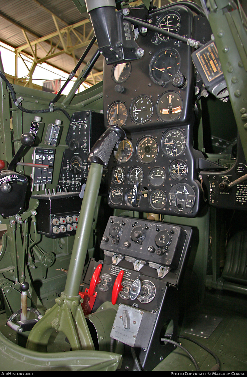
Often enough in museums and private collections, we only see the external controls. For many, this is all they want to see. But what if we also see the internal gears, pulleys, shafts, and bearings to understand how they operate? This is exactly where I now want to go with my future projects.

The Trim Tab controls for the Elevator, Rudder and Aileron are already modelled for the P-39 including the internal components. These dials and controls are currently being manufactured for the restoration project. The decision has now been made to incorporate the working mechanisms as functional replicas. This is great and will actually have some form of function, however, the mystery of operation still eludes the operator. I want to take this a step further and produce desktop models with Clearview casings so that the internals are visible. The exact method is still under review. It will mainly comprise 3D printing techniques for the main components attached to perspex casings.

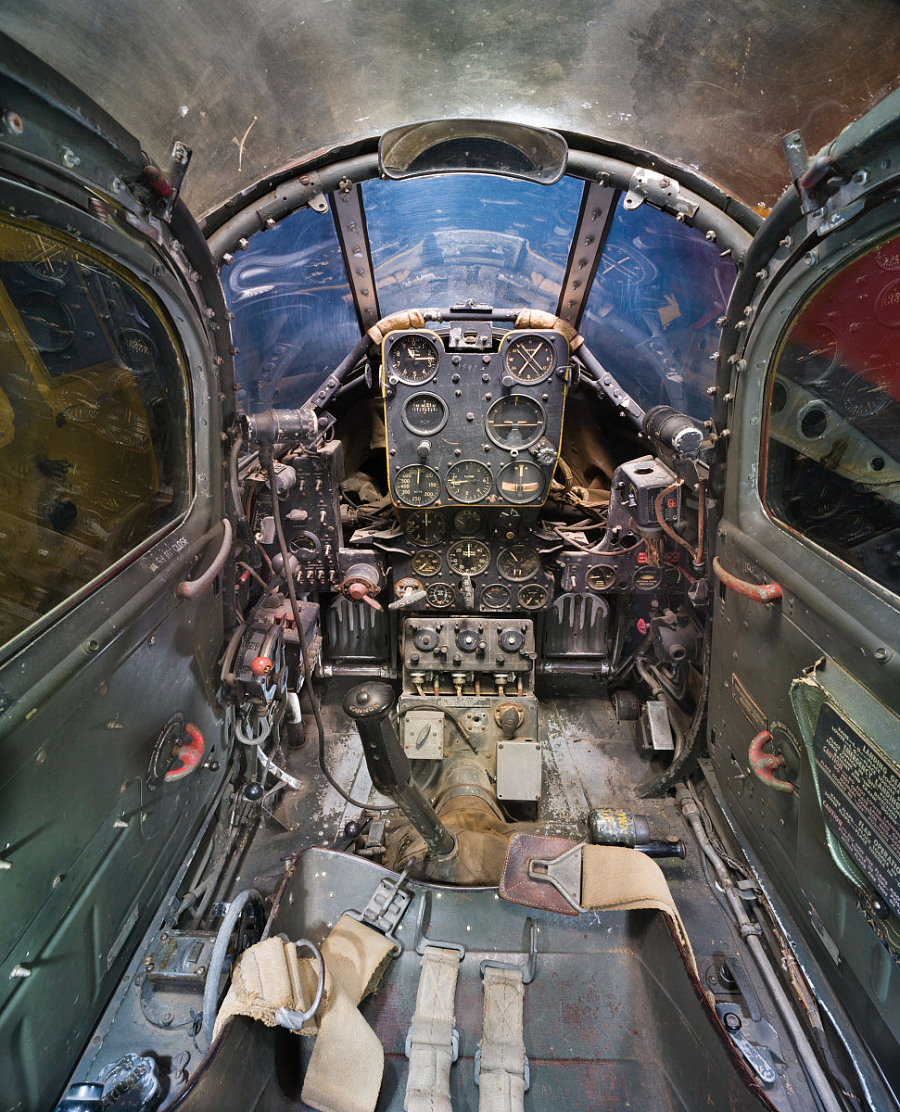
The dials for all 3 controls are similar with the Rudder and Aileron dials operated by a control knob (not shown) and the Elevator Tab controlled by a wheel as shown. At the base of each control dial there is a sprocket for a short Roller Chain which in turn is attached to operating cables. Out of curiosity I decided to have a look at other aircraft to see how alternative mechanisms were developed for the P-51 and the FM2.

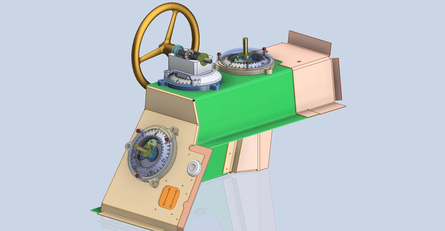
For the P-51 the Trim tab controls are comparable in their operation with the internal gearing arrangements but differ slightly in design.

The dials for the Aileron, Elevator and Rudder are all similar to the CAD model shown. The Elevator and Rudder have cable drums attached to a long shaft for direct cable operation whilst the Aileron has a chain sprocket similar to the P-39 Trim Tab controls.

The plan for the P-51 is to fully model all the components in the assembly shown, complete with cables and chains to simulate operation.

A small point of interest; the various aircraft designed by the same manufacturer often share common parts; for example the NAA drawings for the B-25 share the same Trim Tab control knobs as the P-51 and listed accordingly. For some reason, the P-51 drawings do not reciprocate.

If you can’t find drawings for a particular part, check collections for other aircraft by the same manufacturer. Occasionally, this can be worthwhile. Similarly, with Grumman, many parts were shared with the FM2 and the Grumman Goose.

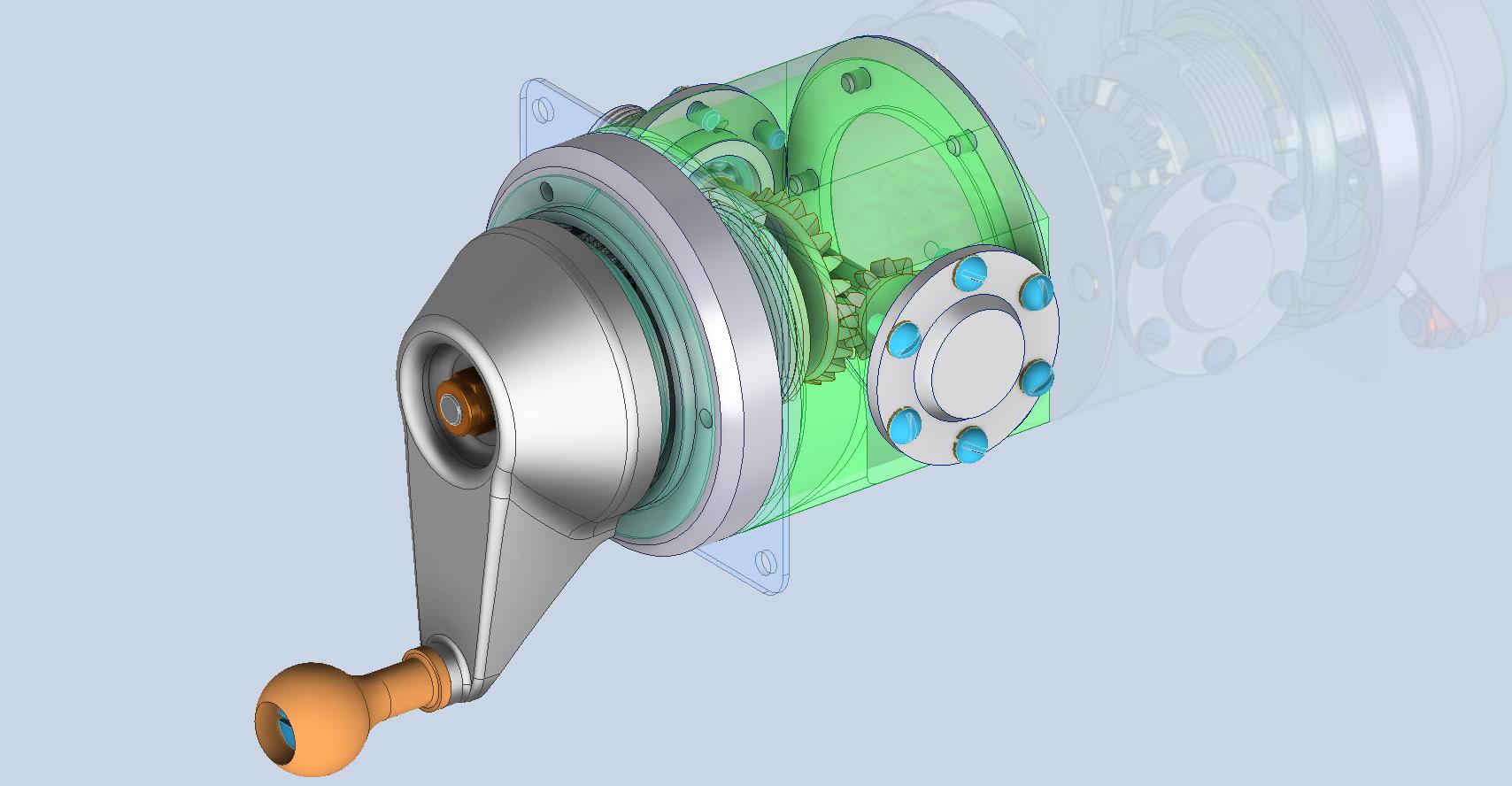
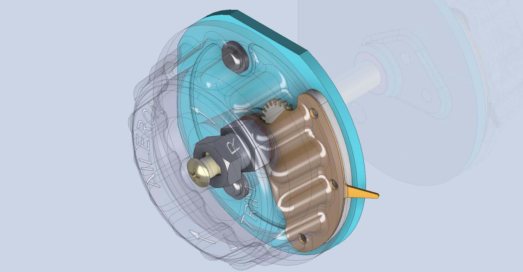
The above model is the FM2 Elevator Trim tab control, the main body of which is typical for the Aileron and Rudder on Grumman drawing 13690. The Grumman Goose has similar controls shown on the Grumman Drawing 13693. Shared components across the various aircraft are listed on the Grumman FM2 drawings.

This Trim Tab control for the FM2 is probably the most complex I have studied so far…requiring very fine manufacturing tolerances. I am not entirely sure yet how this works as there is a complex array of tabbed washers that act as stops for the dial in both directions; it is unclear at this stage how they should be configured…I will get it worked out in due course.

A lot of work to do on these projects which will definitely keep me busy through 2025.

F4F/FM2 Wildcat Canopy

F4F/FM2 Wildcat Canopy:

I have taken a break from the wing development whilst I await more information. So I have switched my attention to resolving the Canopy layout for the F4F/FM2 and true to form I have yet another bunch of questions. I often wonder how on earth they actually managed to build this aircraft.

First of all, we have a layout drawing showing the canopy dimensions…at first glance, it would appear that this will be a straightforward task. However, this is not the case.

We have a number of key dimensions that don’t quite add up…the dimension at “1” is shown as 29.25″ and the dimensions at “2” is 29/875″ but when you compare that with the offset dimensions from the Fuselage Station locations at “3” and “4” there is absolutely no way that “1” and “2” can be correct. The depth dimension at “5” is presumably along the line that would otherwise be defined by the dimensions “1” and “2” but as those dimensions are incorrect then what is this actual dimension relating to?

So I need to figure out what is going on here and therefore I thought I should check the track locations which should provide clarity and verification.

We do have a drawing that details the track components but there are no setting out dimensions for the track relationship to the fuselage. The only other drawing that shows the track is the Structural Assembly drawing…alas that does not help either. The fuselage section above the cockpit shelf is as shown highlighted in yellow. It shows the track and a number of frames that in my opinion are very important aspects of the design but what you see is the only information we actually have. You would think that something as important as a canopy track would be critical to warrant a detailed layout showing the correct alignments and setting out points…there is nothing there! I literally sat here one day reviewing every single drawing in my archive…all 8775 of them to find useful information.

It gets even more interesting as we continue this quest.

The forward section of the canopy has no location information so there is no context as to where this actually resides in relation to the fuselage. Furthermore, although we do have the dimensions for the windshield itself there is absolutely no setout information for the side and top glass surfaces. This is again an area that will require full 3D development, similar to what I had to do with the horizontal and vertical stabilizers. However, I have run into problems with that as well. At Sation 2; the key to getting this correct; is an offset dimension (highlighted in yellow) which is noted as 2.781″ or 2.834″ depending on whether you take into account insulation….so ideally in an “as fitted” condition you have to wonder what the correct fitted dimension should be.

As you can see I have started the 3D development of the cockpit and canopy to hopefully realize pertinent information from individual part drawings and fitting details to determine the missing information and verify the setout for the canopy. This is a lot more work than I anticipated but other than just giving up on this project it is my only option.

I have also reached out to various companies and organizations to try to source more information that will help establish the key parameters I am currently missing. This can be expensive and the reason why I rely heavily on your support so that I can find the answers to these important issues.

I am very close to finalizing the ordinate/dimensional study for the FM2 so it would be a real shame to give up at this stage.

Please help fund these projects so I can find answers for you. Get in touch as usual to hughtechnotes@gmail.com