Grumman F6F Hellcat: Ordinates:

Grumman F6F Hellcat: Ordinates:

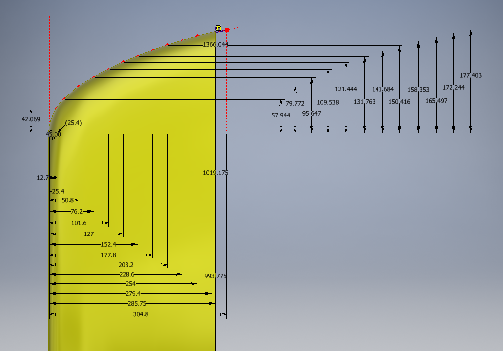
I have come across some interesting information that has provided some clarification of the cowl ordinates. This has enabled me to further the progress of the F6F Hellcat project.

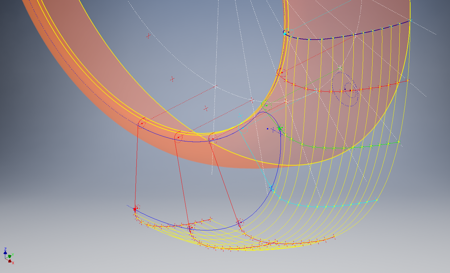
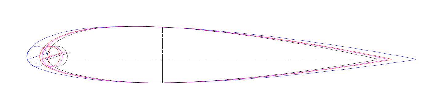
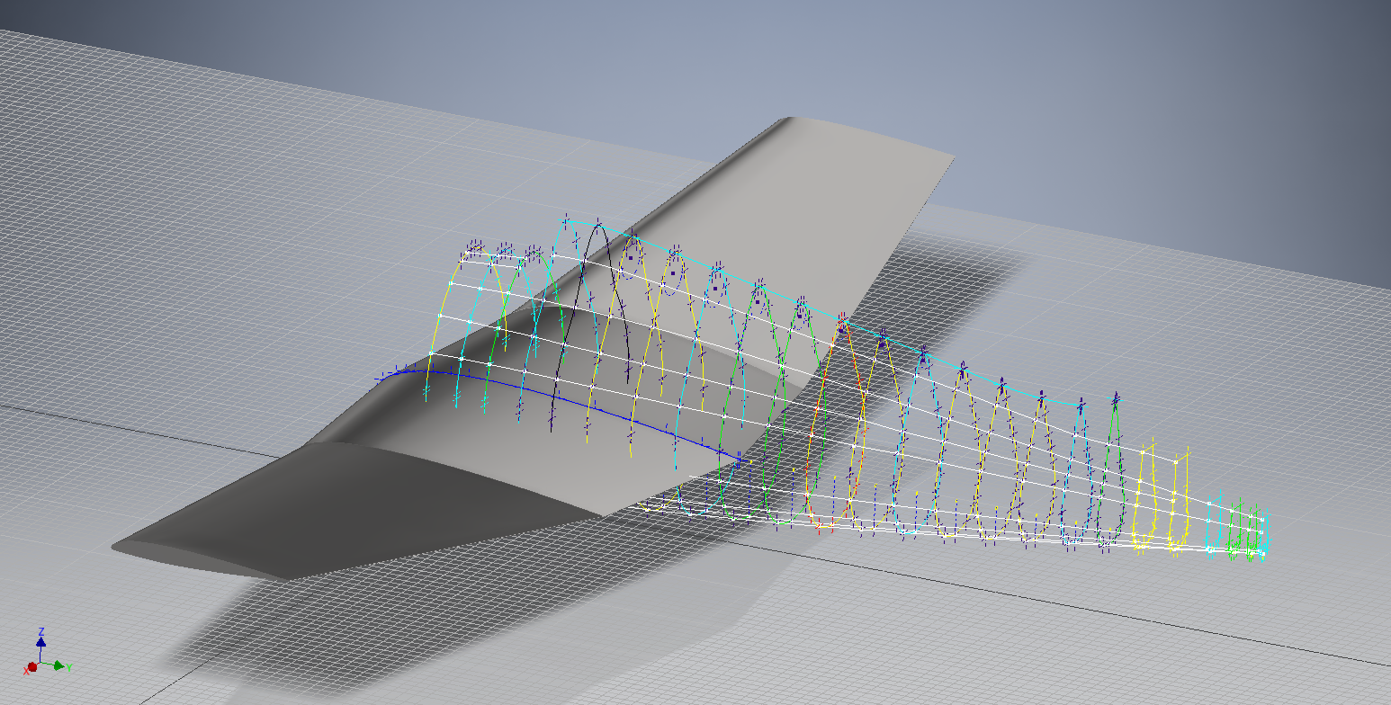
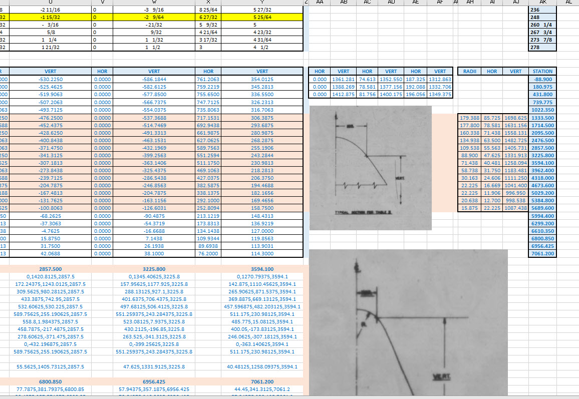
I have also verified the fuselage ordinates which I have subsequently updated. This project is now looking rather good with wings, front nose ring, air scoop, cowl and of course the fuselage ordinates now complete.

F6F-3

As you can see some preliminary work has also been done on the tailfin which will be closely followed by the horizontal stabilizers and eventually the canopy.

It is unlikely that there is sufficient information to fully complete the Tailfin and Horizontal stabilisers ordinate datasets due to the lack of dimensional data for the tail components. At this stage, the best I can do is locate the 2d plans for this area and hopefully return to this project at a later date when more information becomes available. It has been a challenge getting this far with the project.

Hellcat Ordinates/CAD datasets.

Now available online; a comprehensive package comprising detailed spreadsheets (mm and inch) with supporting Grumman ordinate blueprints, Autocad DWG and original Inventor assembly and part files. The entire package covers 90% of the aircraft geometry. See previous posts for detailed discussions on the development.

For all enquiries please email me for details at hughtechnotes@gmail.com.

Grumman F6F Hellcat: Cowl Ordinates

Grumman F6F Hellcat: Cowl Ordinates:

I may have been a tad over-optimistic in my previous article on the F6F ordinates when I mentioned there was a good chance the Grumman ordinate data would be complete. The one exception is the cowl, although there is an ordinate drawing for the cowl the table itself is just a black blob, completely illegible. However, I checked the part drawings that make up the cowl which is quite well detailed so I made a start on the nose spinner ring.

The spinner ring main model is fine and here it is derived into the air scoop construction model. The construction requires numerous contour lines as each ordinate needs to be manually checked due to the poor quality of the original Grumman drawing scan.

Cowl nose ring3

This ordinate drawing is not deliberately blurred by me, this is how it actually looks like. The main dimension is almost legible just the fractions that are problematic. The process will require evaluating each contour line and curvature check, both horizontal and vertical as shown in the above image.

I am hopeful of achieving a good result with this model which will probably take a few days to complete.

Update 27th August:

F6F Cowl Nose Ring2

I have now determined the correct ordinates for each of the seven profiles. Notice the lower profiles have been artificially extended to the center ring, which will give me better results when lofting. After lofting a surface the plan then is to remove the mouth of the air scoop (blue) and apply the finishing flange to the inner edge.

F6F Cowl Nose Ring80

The ordinates are recorded in a spreadsheet with the x,y,z coordinates extrapolated as I previously did for the wings and fuselage.

Update: 12 Sept 2018:

Cowl Ring Cowl Nose setout dimensions verified.

F6F Ring Cowl Nose

Ordinate Dataset Completed: Wings, Fuselage and Front Air Scoop.

The F6F archive of scanned Grumman documents comprises over 7000 drawings in PDF.

Grumman F6F Hellcat: Wing Ordinates

Grumman F6F Hellcat: Wing Ordinates

I wrote an earlier article on my work with the F6F fuselage ordinates which I have recently updated. Whilst revisiting the archive I also came across the Grumman wing ordinate drawings and decided to develop those as well. I was reluctant to do this as the original drawings were not that great.

Thankfully it was not as bad as I first suspected, though it has taken me over 7 hours to painstakingly enter each ordinate manually to tabulate the ordinates in Excel.

F6F Wings

I still have to interpolate the data to generate the appropriate X, Y, Z coordinates; set out from the 35% chord; which I will endeavor to do over the next few days.

F6F wings 2

To verify the ordinate dimensions the following equations are applied. The chord length is for any wing chord whilst the LER is only applicable from station 75 to station 252.

f6f calcs2

To be honest the F6F Hellcat was not even on my to-do-list but a conversation with a colleague about the F6F performance characteristics prompted me to have a closer look at the archive. Surprisingly it is very possible that this archive may have sufficient information to generate an entire aircraft ordinate set, which is quite rare.

f6f

I will update this post when the wing model is complete, so come back soon.

Update August 23:


I have checked the Centre section profile for accuracy and noticed one point out of alignment by 2mm towards the leading edge. Removing this point allowed the natural curvature of the spline to define an acceptable profile as shown. The curvature check shows that this curve now matches the Leading Edge Radius.

The trailing edge extends beyond the 100% Chord by 5/8th inch on the centre section (Station 0) which tapers to zero at Station 252. Drawing a straight line segment from the Trailing Edge Radius results in perfect alignment with the spline.

Centre Section Stations:

f6f ctr section

Outer Panel Stations:

F6F outer wing

It is not unusual to have a few rogue points from the tabulated ordinate data which is why it is important for a detailed analysis like this.

And here, at last, the complete wing assembly:

f6f wing assembly