My Project Plans For 2024

My Project Plans For 2024:

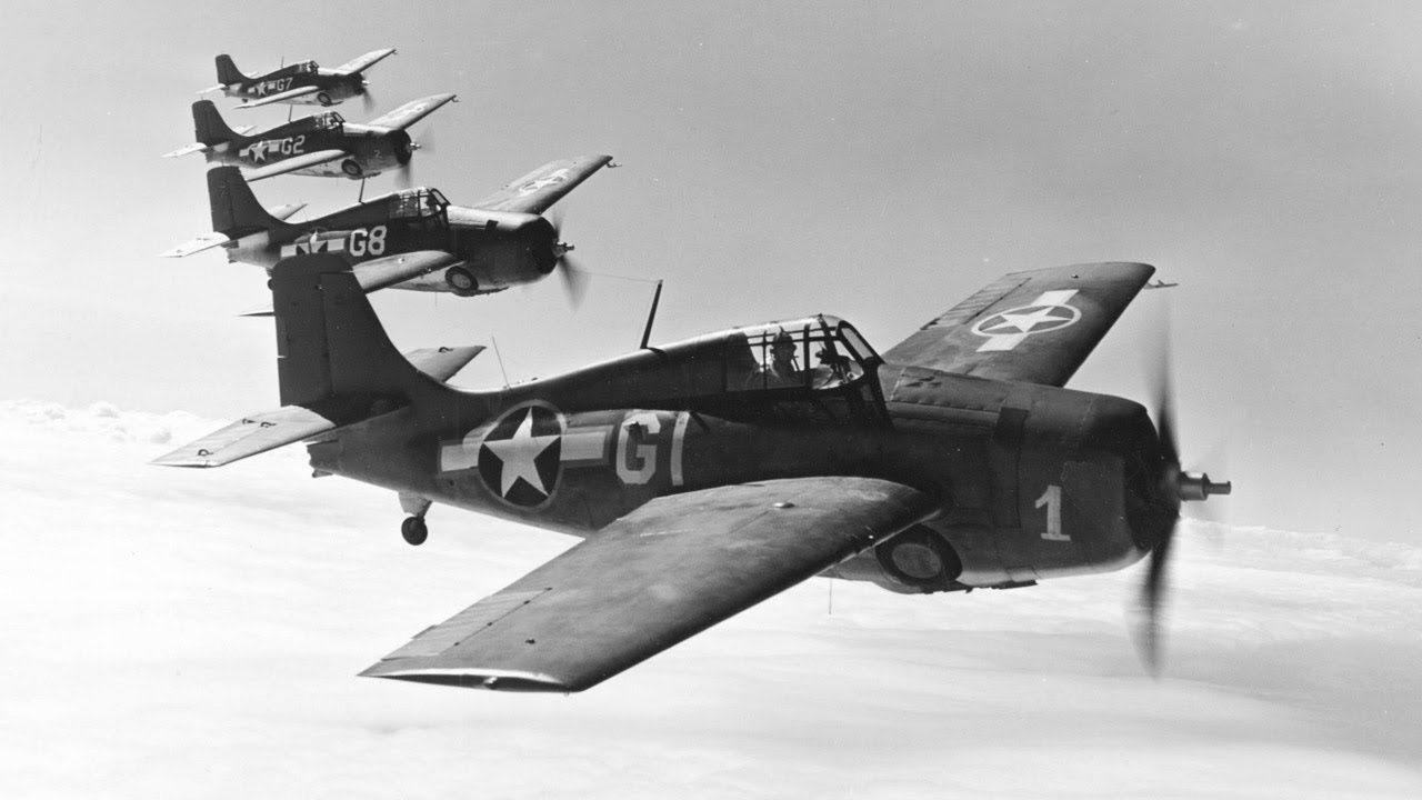
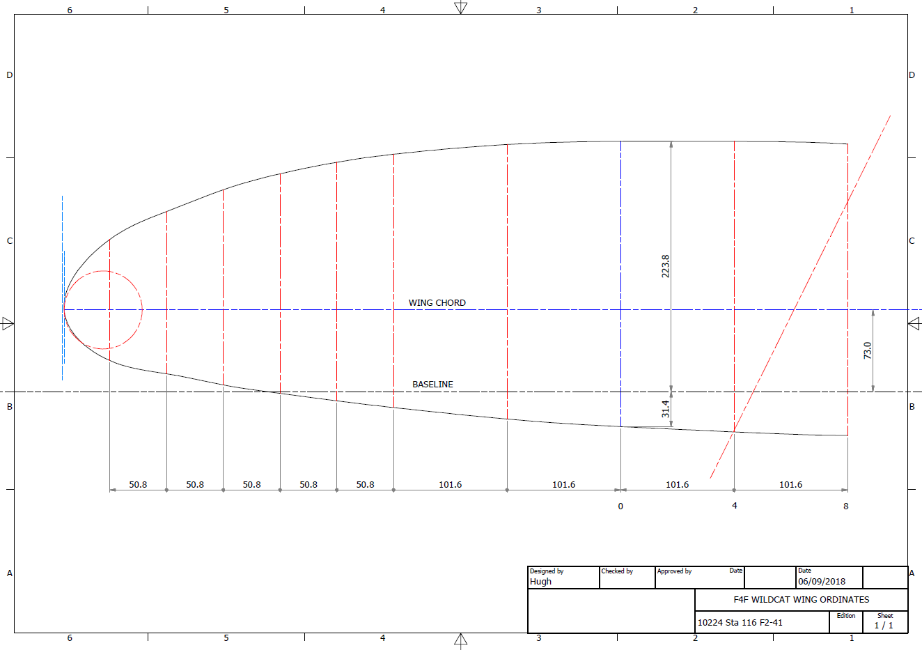
The primary project for 2024 will be the F4F/FM2 Wildcat development. I aim to have a highly detailed structural model at either 1:10 or 1:15 scale 3D printed by the end of the year. Due to the requisite accuracies, this will be MSLA resin printed. My work is simply to produce the most dimensionally accurate aviation models in 3D CAD and accordingly fully documented.

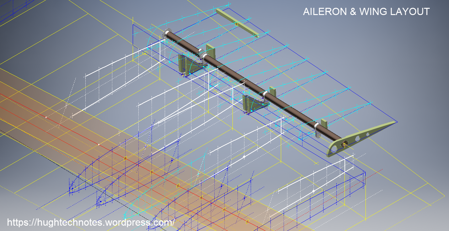
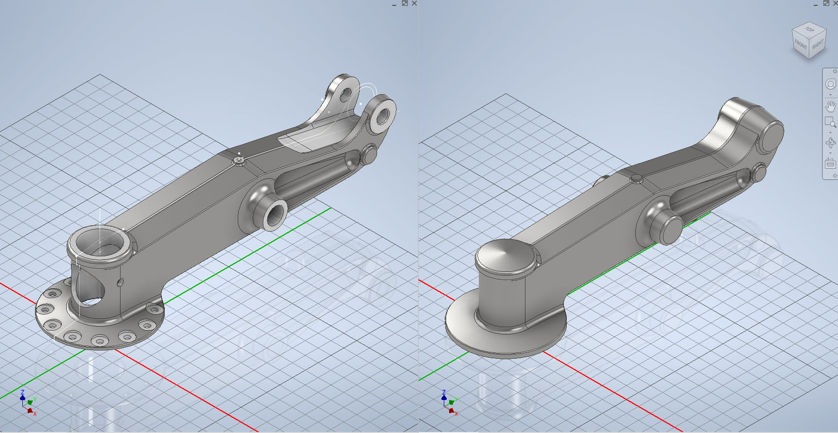
I have recently started building the Landing Gear for the F4F which is shown below; this is the axle part # SP597. The image on the right is the forged model which is derived for machining into the part on the left.

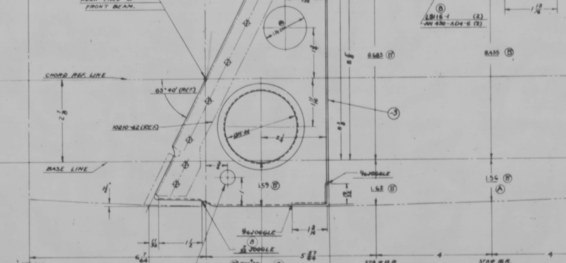
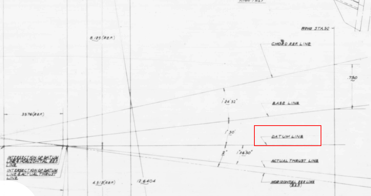
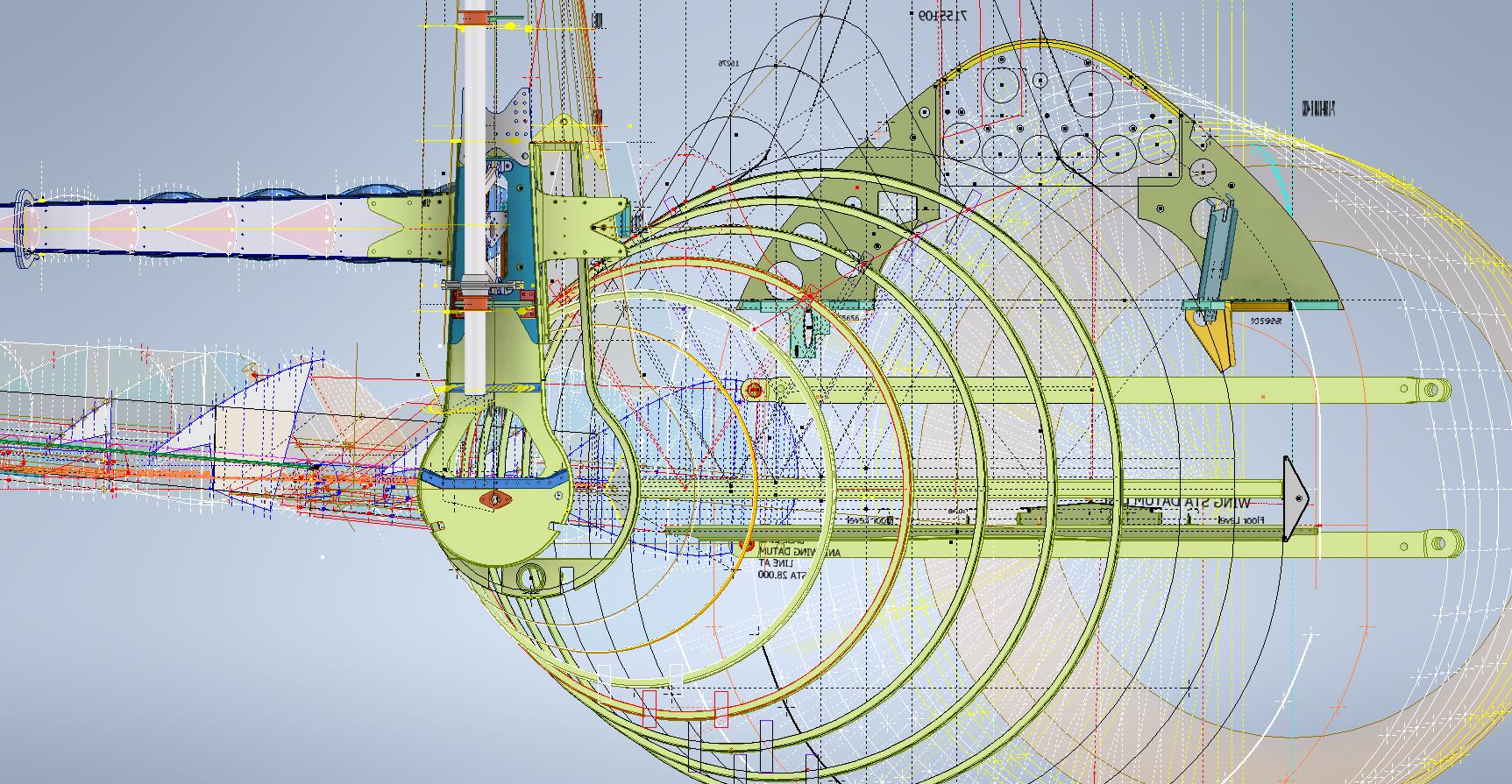
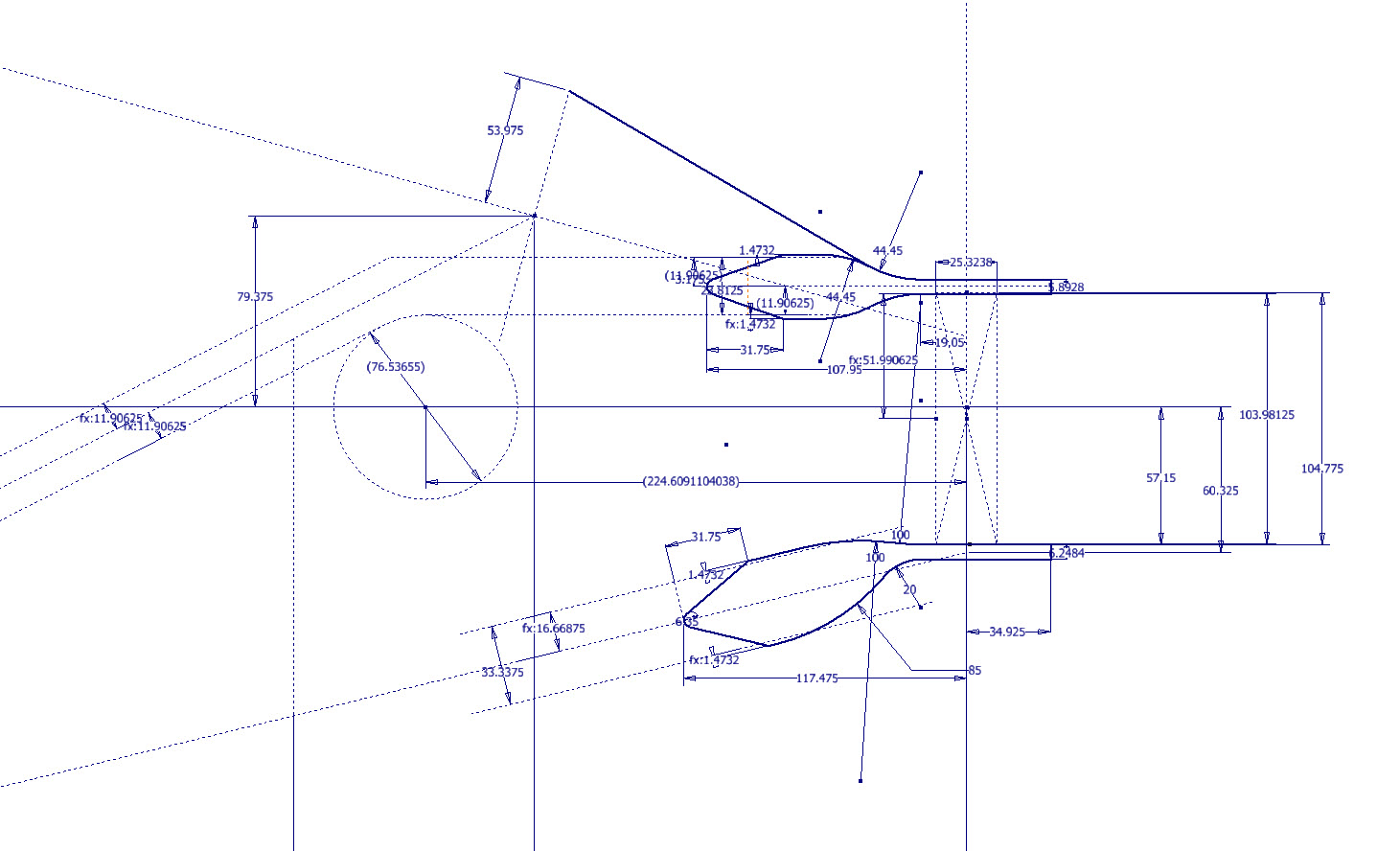
Another example is again the Landing Gear; this time the Lower Drag mechanism. Through exhaustive research, I can go from an almost illegible blueprint to a clear sketch on the right. This is why I do what I do.

The other aircraft I will be revisiting is the P-38 Lightning as some aspects of that project warrant further research. For both aircraft, I will be visiting the collections at RAF Cosford and Shuttleworth later this year to hopefully fill in some of the blanks.

The projects will also involve updating my blueprint archives to make it easier to search for drawings initially by renumbering all 8000 plus drawings inclusive of drawing numbers. I have already started this for the F4F Wildcat which was helped enormously by some clever folks on YouTube. https://youtu.be/I9ffWZ_Bt6o?si=OEog79e-XaRUZz7K

The first portion of the numbering sequence is the original scan reference followed by the actual drawing number. The An Parts library will also be updated with additional conversions for use in other CAD systems.

2024 will no doubt be a busy year for me with the 1:10 scale printed model being the biggest challenge.

I hope that you will continue to support my endeavors throughout this year. Happy New Year.

F4F/FM2 Wildcat Canopy

F4F/FM2 Wildcat Canopy:

I have taken a break from the wing development whilst I await more information. So I have switched my attention to resolving the Canopy layout for the F4F/FM2 and true to form I have yet another bunch of questions. I often wonder how on earth they actually managed to build this aircraft.

First of all, we have a layout drawing showing the canopy dimensions…at first glance, it would appear that this will be a straightforward task. However, this is not the case.

We have a number of key dimensions that don’t quite add up…the dimension at “1” is shown as 29.25″ and the dimensions at “2” is 29/875″ but when you compare that with the offset dimensions from the Fuselage Station locations at “3” and “4” there is absolutely no way that “1” and “2” can be correct. The depth dimension at “5” is presumably along the line that would otherwise be defined by the dimensions “1” and “2” but as those dimensions are incorrect then what is this actual dimension relating to?

So I need to figure out what is going on here and therefore I thought I should check the track locations which should provide clarity and verification.

We do have a drawing that details the track components but there are no setting out dimensions for the track relationship to the fuselage. The only other drawing that shows the track is the Structural Assembly drawing…alas that does not help either. The fuselage section above the cockpit shelf is as shown highlighted in yellow. It shows the track and a number of frames that in my opinion are very important aspects of the design but what you see is the only information we actually have. You would think that something as important as a canopy track would be critical to warrant a detailed layout showing the correct alignments and setting out points…there is nothing there! I literally sat here one day reviewing every single drawing in my archive…all 8775 of them to find useful information.

It gets even more interesting as we continue this quest.

The forward section of the canopy has no location information so there is no context as to where this actually resides in relation to the fuselage. Furthermore, although we do have the dimensions for the windshield itself there is absolutely no setout information for the side and top glass surfaces. This is again an area that will require full 3D development, similar to what I had to do with the horizontal and vertical stabilizers. However, I have run into problems with that as well. At Sation 2; the key to getting this correct; is an offset dimension (highlighted in yellow) which is noted as 2.781″ or 2.834″ depending on whether you take into account insulation….so ideally in an “as fitted” condition you have to wonder what the correct fitted dimension should be.

As you can see I have started the 3D development of the cockpit and canopy to hopefully realize pertinent information from individual part drawings and fitting details to determine the missing information and verify the setout for the canopy. This is a lot more work than I anticipated but other than just giving up on this project it is my only option.

I have also reached out to various companies and organizations to try to source more information that will help establish the key parameters I am currently missing. This can be expensive and the reason why I rely heavily on your support so that I can find the answers to these important issues.

I am very close to finalizing the ordinate/dimensional study for the FM2 so it would be a real shame to give up at this stage.

Please help fund these projects so I can find answers for you. Get in touch as usual to hughtechnotes@gmail.com

F4F/FM2 Wildcat Wing Questions 2

F4F/FM2 Wildcat Wing Questions 2

I have given this article the title of “Questions 2” as moving on from my previous post on the FM2 wing, I have identified another anomaly that I cannot explain…another chapter in the development of the FM2.

This relates to the wing trailing-edge ribs that cover the main flaps. Normally, when you set out a win,g the wing chord is divided into percentages which would then provide a straight line segment on the surface when lofted between root and wing tip profiles.

For the Wing Trailing Edge rib profiles, this is not the case. At the wing 80% chord line, the top surface calculates with minimal deviation, as one would expect, similarly at the extreme wing tip. However, between 85% and 90% rib chords the deviation is not as expected. The contours at 85% and 90% trace a curve where you would expect a straight line.

What appears to be happening is that the wing TE ribs are dimensioned at various stations from the main Rib Sta 0. At stations 48, 52, 56, and 60, the offset dimension from the Baseline is the same for each rib at each of those locations. The end result is that the wing top surface is actually perpendicular to the wing root chord and does not follow the transition lines you would expect on a conventional wing loft. The transition lines at chords 85% and 90% are curved as you can see from the calculated offset tables below, which would normally be expected as a straight line.

At 80% and 95% chords respectively the wing top surface is for all intents and purposes a straight line as you would expect. The residuals column in the above tables shows the necessary correction offset for the selected point to align with the calculated Best Fit Line in millimeters. It could be argued that the offsets are no greater than +/- 1mm, which is not very much, but the flap ordinates are as shown and could have easily been dimensioned to a 1/64th inch had the draughtsman intended to show something other than they did. This alone demonstrates deliberate intent. So far I have identified alignment issues with the Flaps and Ailerons in my previous post, and this anomaly just adds more questions.

I know that this plane was originally conceived as a BiPlane, which explains the 5 datum lines we have for the wings and I am curious whether that design decision introduced a number of key aspects from which these questions have arisen. The truth is at this stage, I do not know, though the Flaps can possibly be explained; everything else is a mystery.

I have searched and read many forum discussions on the FM,2 and as far as I kno,w none of these issues have been identified or discussed… even the fact that the wing tip NACA profile is not a typical 23009 I suspect should have raised some red flags. Identifying and finding answers for design issues like this is part of the reason why I do what I do.

Grumman F4F/FM2 Wildcat Update

Grumman F4F/FM2 Wildcat Update:

Following on from my previous posting regarding the Excel Transpose function; wherein I mentioned the updates to the Grumman F4F/FM2 Cad/ordinate dataset; I thought I would share a few screenshots of progress so far.

As you can see the aircraft is partially 3D modeled…there is actually a good reason for this other than the fact I enjoy the 3D modeling! I have found that on the main assembly layout drawings, the dimensions are often shown to one side of the spar whereas the actual connecting part is defined to the other side. To ensure I get this stuff right I would model the main spar to correct material thickness and check alignments. Admittedly I did get a bit carried away with modelling some of the ribs.

The wing is probably the most complex assembly to do due to the main ribs being in 3 parts…the leading edge, mid-section, and the trailing edge. Each profile will be recorded separately; as per the Grumman drawings and then compiled to provide full rib profiles at each station. The wing also has 5 datum lines that are occasionally misidentified in the part drawings which can be really frustrating alongside incorrectly placed dimensions…generally wrong vertical dimensions are associated with the wrong rib station, more common than I would like.

Still some work to do to finish these main areas as well as the cockpit canopy, fuselage, and front cowl. I haven’t looked at the undercarriage as yet… development of that will be dependent on available information…we will see!

It is not my intention to fully 3D model this aircraft but where it helps check associativity between parts then I will. The project will fully develop all key profiles for ribs and frames which will be fully documented on Excel spreadsheets as a permanent dimensional record. I plan to have this update completed by the end of September.

The aim of these cad/ordinate datasets is to produce the most accurate dimensional records available anywhere for the various aircraft…nothing is assumed or taken for granted.

If you can help me with the spiraling costs of these projects please consider making a small donation. As usual for all enquires please get in touch at hughtechnotes@gmail.com

Grumman F4F Wildcat: Wing Ribs:

Grumman F4F Wildcat: Wing Ribs:

Recently I received an email asking if I had done any work with the Grumman F4F Wildcat. As I do have an archive for this aircraft it was indeed on my to-do list. This inquiry prompted me to have a closer look at the archive to see what information was available to derive a working ordinate dataset.

F4F Wildcat

Similar to the P-39 the archive does not contain tabulated data but the part drawings do have the ordinate dimensions. Working to derive an ordinate dataset from part drawings as you can imagine is quite intensive work as you first have to collate the drawings and then develop the profiles in CAD and then extract the point data to a spreadsheet. A complete reversal of the normal process.

The work I was doing for the F6F Hellcat previously was not a priority task so I decided to do some development on the F4F Wildcat, starting with the wings. This threw up a few surprises as the wing rib dimensions were not relative to the wing chord as you would normally expect, instead, they were from a Base datum line. I had not seen this before and it transpires that the reason for this is because the wing ribs are actually not perpendicular to the wing chord. They are in fact perpendicular to wing datum line.

F4F Wing Ribs

This next image shows a simplified sketch of how the dimensions are shown on the Grumman drawings. Note also that the vertical divisions are dimensions fore and aft of the “0” line (which I take to be the vertical datum) and not percentage breakdown of the cord length as expected.

F4F Wing Ribs2

This raises all sorts of questions as to why Grumman designed the wing structure in this manner. I cannot think of any performance or manufacturing benefit in doing so. You can also see in this scrap view from an actual Grumman drawing how the dimensions are to the baseline and not the chord line.

F4F Wing Ribs3

I posted a similar question on the WW2 Aircraft forum, so hopefully, someone will enlighten me on this unusual design feature.

Update: Solved!

The wing ribs are perpendicular to the Wing Datum line, which is 1.6 degrees from the Thrust Line (essentially the design horizontal axis) that aligns with the fuselage Thrust Line. It transpires that the various wing components are dimensioned relative to any one of 5 different datums depending on their function.

2018-09-16_01-23-03

Update Sept 2018: Work in Progress:

F4F Aileron 2

2018-10-06_19-18-41