Technote: Excel Transpose Row to Col.

Technote: Excel Transpose Rows to Columns:

I am currently updating the F4F (FM-2) Wildcat Ordinate dataset which required transposing Excel Rows to Columns so I figured I should write a quick Technote on the process involved.

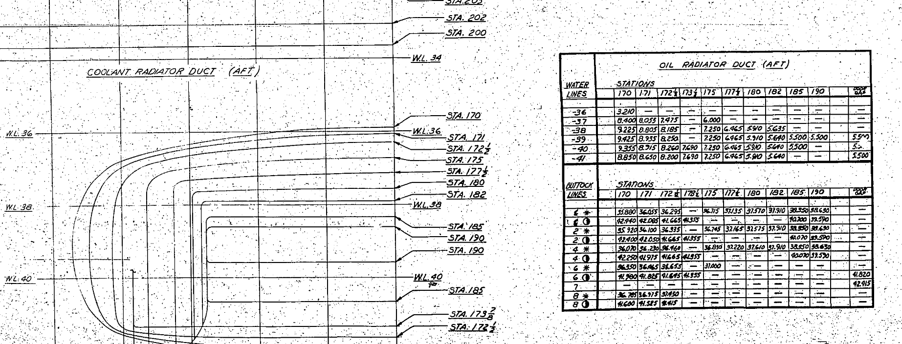
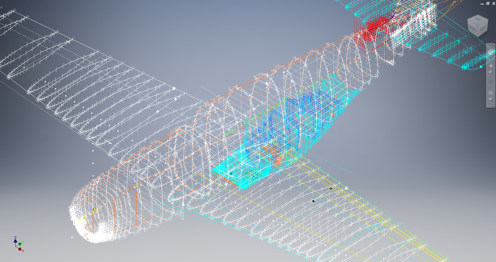
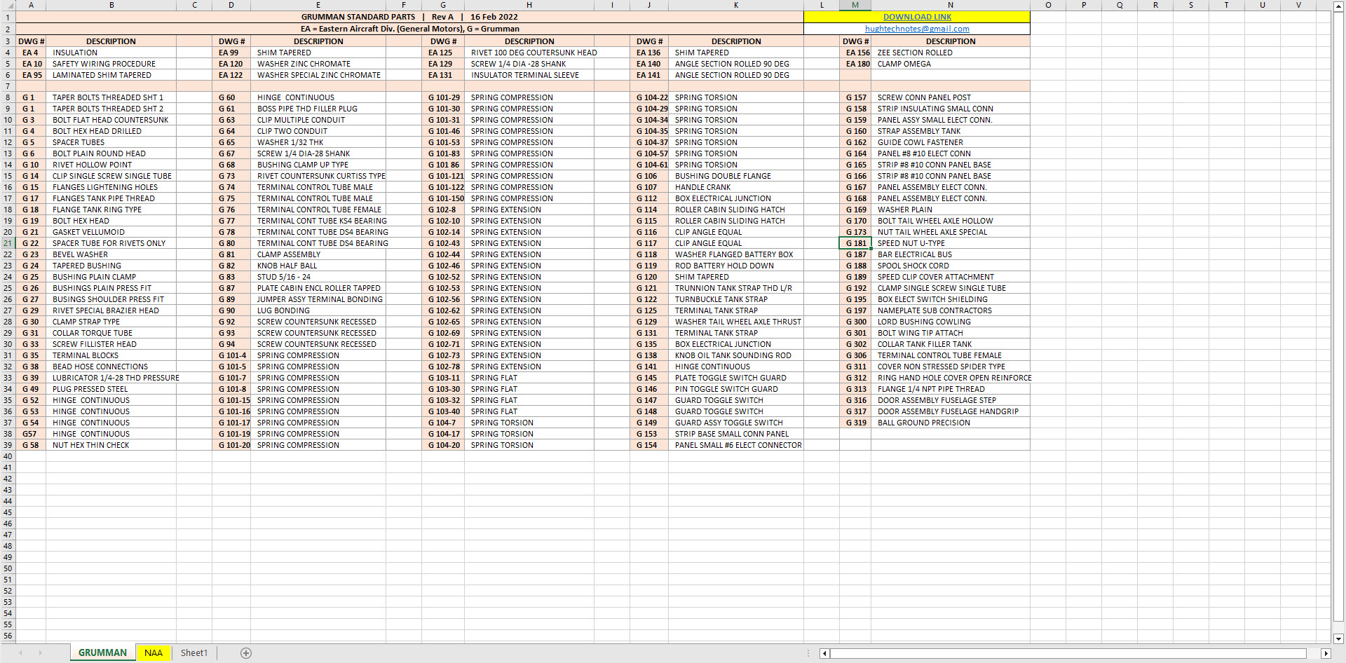
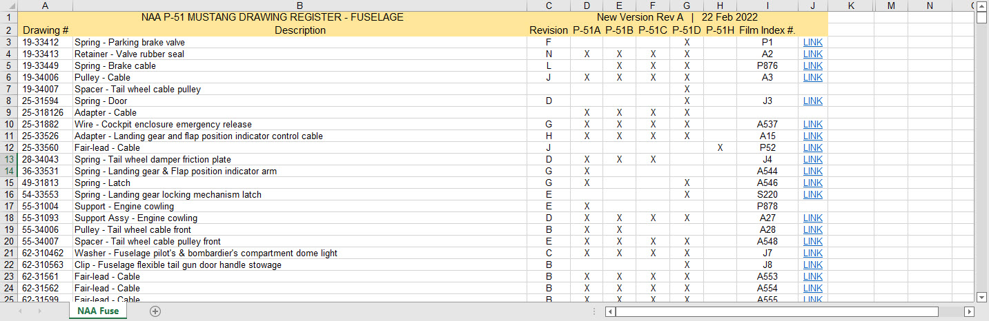
Before I get into the detail it is necessary to appreciate that I could have saved myself a bunch of work if I simply created the table in the first place with the columns and rows reoriented to better suit the required end goal. When I develop these tables it is important that the layout is the same as the original data so that ongoing cross-referencing and updating are much easier to achieve. As you can see in the screenshot of the original drawing the tabulated information is not very clear, in fact, some of it is completely illegible… which incidentally is the primary reason why I do this in the first place…initially, I develop the coordinates as best I can and then create the profiles whereupon any variations can be visualized and therefore corrected…essentially working from what we know to determine what we don’t know.

Getting back on track. What I need to do is to create a live link to the rows (highlighted) but in a columnar format to list the required X, Y coordinates for each profile. You could of course just simply copy the rows and use the Paste Special function to transpose the values to a column…however, the copied data is not linked so any changes will not be apparent in the column values. The best way I found is to use the INDEX function.

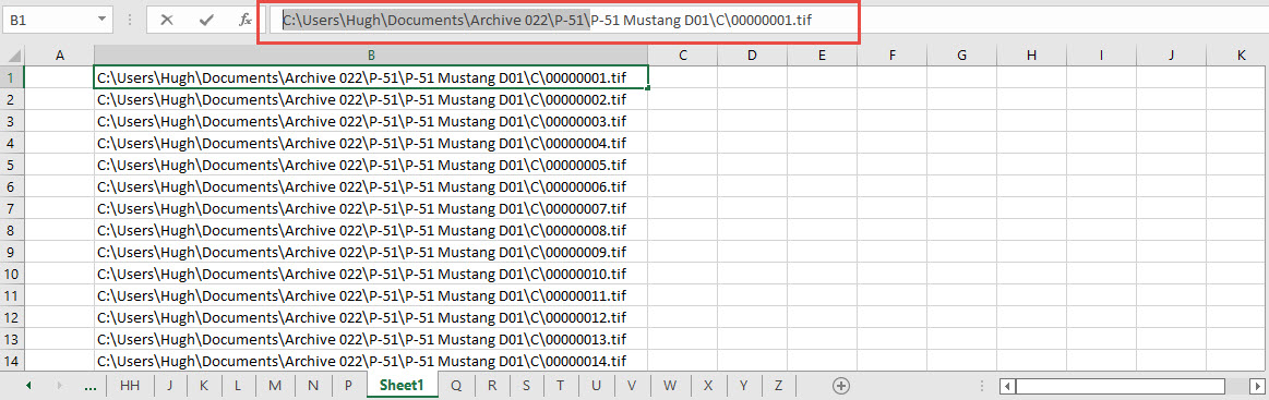
With the INDEX function, you first need to establish a range of values to be indexed…in this case, it is the values from the table shown in the red border… which give us the range from L64 to P90 (press F4 to lock that in).

The value A1 after the Column and Row values is related to the first entry in the range…it does not relate in any manner or form to the actual cell A1. I have shown alphabetically in the first image above how this A1 would change according to the values selected. So you would write this formula at the top of the column where you want the values transposed, select this cell, and use the + sign at the bottom right to pull the values down. For each column you would have a different starting point…for example, in the very first column (X-Coord) the Formula would be written as follows:

It is alphabetically the 3rd row from the first selected cell in the specified range and numerically in the first column. For each group of values you need you would adjust the starting point of the selection to the first value in the row required. When you get the CAD/Ordinate dataset for the F4F Wildcat the spreadsheet is fully editable and you will see for yourself how this was done.

As usual for further details get in touch hughtechnotes@gmail.com

Fastener Library Update: AN/MS Standards

Fastener Library Update: AN/MS Standards (Updated Jan 2024)

Over the years I have been further developing my AN (Army/Navy) or MS (Military Standard) parts library and only this morning did I eventually get around to uploading all the new files.

This is the list of Standard Fastener Parts now currently in the library…over 300 parts.

I have decided to make these files available as the original Inventor iParts. I was getting requests for different conversions to STP, Parasolid etc, and also at different scales…doing all that on request takes a lot of time. Don’t be put off by the fact that they are Inventor files as Inventor is readily available as a 30-day trial product which gives you several options for working with these parts. You can even install a Read Only version of Inventor

It is really simple to work with these files…let me show you. For a start, an iPart is actually a normal IPT part file inclusive of a table of parameters so you can generate multiple variations of the part in one file.

Part Conversion: I would assume that many people who don’t use Inventor will wish to convert to a file format more suited to their application.

You can tell you have an iPart when the icon next to the part name in the model browser is shown as a table. To convert the file you simply expand the table folder; select the part or multiple parts and select generate files which will create a single IPT part file for each variant. This is placed in a subfolder named the same as the iPart filename. From there you can open this part file and Export whatever model format you want. Alternatively, if you would like to build your own version in a different CAD system it is useful to use the underlying sketch which can be Exported from this model; as shown in the second image which you can link separately to the Excel spreadsheet.

Table Editing: As I mentioned the part has an internal parameters table a bit like the format used by Excel which is fully editable. For the majority of the Library Parts, I also include the Excel table as a separate file.

Accessing the Table is as simple as right-clicking on the “Table” text and selecting what editing option you want…either “Edit Table” (which opens the part table itself) or “Edit via Spreadsheet” which will open this same table in Excel. When you save the table in Excel it will revert to the Cad Part file and update the model with any changes. Making changes is much easier in Excel where you can add new variants of the part or amend existing ones. The dimensions are all in inches but if you bring this part into an mm metric part it will automatically adapt the inch dimensions to mm…so you can be assured that the part will be correct regardless of which units you use.

These part libraries include the most commonly used sizes so you can add to this as you desire. A copy of the original specifications is also included for reference. If you are looking for Aviation-related specifications then check out this free site: http://everyspec.com/library.php.

This library is included in all the CAD/Ordinate datasets and is now also available as a separate package. See this page for more details: https://hughtechnotes.com/resources/

Manufacturers Standard Drawings:

Included in the many blueprint archives are manufacturers’ Standard drawings, some of which are commonly shared specifications between various aircraft by the same manufacturer. I have a spreadsheet listing those standards for both Grumman and North American Aviation. This is available free at this link:

Manufacturers Standards (NAA and Grumman)

In the top right-hand corner of each worksheet is a link to a separate download area where all those standard drawing files are stored. As usual, the spreadsheet is fully editable so you can add to the data record as you find more information. I am sure you will find this is a beneficial resource by having all these important standards in one location. If you find these useful please consider a small donation to help support my work.

New Project: Standard Part Libraries

New Project: Standard Part Libraries

Many moons ago I started a project to develop libraries of Aeronautical standard parts according to the various National and International standards pertinent to aircraft design and maintenance noted in this article.

https://hughtechnotes.wordpress.com/2015/07/26/naa-p-51d-mustang-standard-part-models-specs/

Using the original standards from the wartime era and the updated, often replacement standards, I figured it would be a good idea to develop this project further. I am aware that there are many different CAD systems so it would be folly to just develop this for just one product.

The above products are currently available in the Resources Tab of this blog and though included with the Mustang P-51 Ordinate/CAD dataset are standard for many aircraft of this era and accordingly are available separately. This existing collection is already very comprehensive with over 300 parts modelled and listed, though these are in line for an overhaul and update.

Moving forward with this project I will develop the configuration spreadsheets exactly as per the original specification tables set out plus any additional dimensional data that will be required for modelling. This will be accompanied by a DWG file as a template to use when developing your own equivalent of an iPart. Essentially putting together a dataset that anyone can use regardless of what CAD system they are using.

Additionally, standard metal work profiles will also be developed and produced in a similar manner.

There is a catch: This will take a while to do and probably won’t be ready until October. Typically the study will comprise a basic dimensioned drawing exactly as per the reference Standard with accompanying spreadsheets. There will be separate spreadsheets for each part number in a collective Standard, though there may be only one drawing. For example AN21 THRU AN37.

The way to use this dataset; regardless of the CAD system; is to first develop the part model naming the parameters as defined in the spec (you can use the DWG for your sketch template). In this example, the first 2 columns are generic to the specific CAD system with the first column being a unique value. From LENGTH to Dim P, in the table, these are the main geometry parameters. The Hole1 column has values “Suppress” or “Compute” which is an instruction to exclude or include the hole. The Thread parameters are defined as a Designation and Class which are standard integral parameters; those names may vary accordingly. Typically in Inventor, they can be found in the iParts Author as follows:

Once you have your Part modelled, open the iParts author and set up the first line of the table…you just need the first line at this stage Close the Author and open the table in Excel and copy the contents of the provided spreadsheet data tables above… ignore the header/titles. The iPart table will now be updated with all the above variations. It does not matter if your part template is Metric or Inches as the part dimensions are predefined as inches and will automatically recalculate depending on your template standards. You can of course already do this with the existing iParts but they are not inclusive of dimensioned drawings…so you have a bit more work to do referencing the actual standards for parameter names. That’s what this project work is designed to do…essentially finish with full documentation.

These spreadsheets and CAD profiles will enable anyone to very quickly develop a standard library in their own CAD system…an important resource and time-saving endeavour. I should note the actual AN and MS standards are available online for anyone that wants to access them. I have provided a link below to my previous article on this subject.

https://hughtechnotes.wordpress.com/2022/02/17/technote-manufacturers-standard-parts/

Update 27th July 2022:

Blimey, this is quite an awesome task…I envy those that build the standard libraries in the many CAD systems that contain thousands of parts…this will definitely take a long time.

Many of the parts are relatively straightforward like Bolts, Castle Nuts, Clevis Pins etc that require nothing more than basic dimensioned drawings. Occasionally though many parts will require additional sketches to clarify the profiles, like this AN667 Terminal Fork End. Also in similar cases, the model will be dimensioned to As-Fitted/Swaged for use in assemblies. You can basically ignore the Scale as all the DWG versions of these drawings will be 1:1 according to the part number actually modelled.

This is a list of the Specifications I am currently working on. Many of these are updated versions of the existing standards available on the CAD Resources page. The updates include marginal improvements to the 3d models, additional data and verification of listed dimensions. The data sets also include dual part numbers where an item has been updated to a newer standard the new designation is noted alongside the old.

It is very important to get this stuff right, to ensure the part designations and representations are correctly defined in the assemblies. Have you ever tried to figure out assembly configurations from the NAA assembly drawings or picked your way through the Parts catalog just to identify a single connection for a clevis, nut and bolt, turnbuckle or whatever…it is time intensive. It was this desire to bring clarity to these assemblies that I created the P-51 Mustang cad models shown below, which incidentally was the catalyst that drove the development of these Part libraries.

Get in touch with any inquiries at the usual email. hughtechnotes@gmail.com

Technote: P-51 Mustang Drawing Register Updated

Technote: P-51 Mustang Drawing Register Updated

There seems to be a theme developing here…following on from my efforts to organise the chaos of large blueprint collections I endeavoured to continue my efforts with a long-overdue update to the P-51 Drawing register.

The P-39 Airacobra register was a breeze by comparison to this P-51. That was only a matter of 4-5 hours of work which was aided by the fact the drawing filenames were already fully described…all I had to do was add the Film Index numbers alongside the filenames. The P-51 on the other hand only had obscure filenames that were somewhat inconsistent…which meant this exercise ran into a few days. Occasionally my enthusiasm tends to thwart common sense!

Getting back to the P-51 Drawing register. The update is now inclusive of hyperlinks contained within the excel spreadsheets that will open the associated drawing. This is a huge step forward in managing and working with such a large archive and though it took ages it is a major improvement.

As you can see LINKS have been added to the right column (J) with hyperlinks recorded in column L. This column is hidden but can easily be viewed by using the option to UNHIDE. The Film Index reference is the actual microfilm reference hard coded onto the original film which differs from the actual filename that was generated when the film was scanned.

I should note at this stage that a number of folders in the archive will require renaming as Excel does not like #hashtags in naming conventions. The download section includes a word document describing the file-naming convention.

The hyperlinks are plain text entries originally copied from the development process that utilised the Vlookup function referencing a separate spreadsheet. I had considered including the separate spreadsheet in the download section but I think that just over-complicates things. About that development process!! It may be prudent to provide a quick overview of how things were developed.

The Development Process (briefly)

The initial process was to extract the filenames from Windows Explorer and deposit those records into a separate spreadsheet. The way to do this is to select all the files in the folder and click the Copy Path option in the windows explore toolbar.

Paste this into a spreadsheet and then remove the first part of the path (highlighted) so the location parameters now become a relative path to the root folder. This was done using the Replace (CTRL+H) function by copying the highlighted portion and applying a null space to all of the records.

This is now the actual hyperlink path which we need to associate with the actual Film Index. As mentioned above the Film Index is recorded on the scanned images and therefore a fair amount of manual intervention is required to record this value in column A. Using the Vlookup function necessitates that we use the column on the left for the value sought to return the value on the right. As you can see from the many tabs on this spreadsheet I filtered out all the filenames from every folder and then proceeded to populate the column in each case with the Film Index number…that drove me nuts!

There are several ways of accessing the values using Index and Match or even Indirect in conjunction with Vlookup…but we shall stick with the simple option of using Vlookup.

The Vlookup function asks for an initial lookup value; in this case “I10” then it asks for the corresponding Table Array; essentially the array of data from which to search. In this example, the array is defined as the values from the spreadsheet called “FILELIST” Tab “A” from cell A1 to B1043. The “2” refers to the column from which to extract the value you are seeking…which refers to the second column. “False” is for an exact match to the value in I10.

The Link is simply the =HYPERLINK function referencing the value in column K with a text value defining the label “LINK”.

You can combine the HYPERLINK function with the VLOOKUP in one formula like this…though it does take a fraction longer for the link to open.

That’s the basics of how this was done. using Indirect in conjunction with Vlookup enables you to search for the tab designation from a tab list that would look through the entire spreadsheet for the sought value. I didn’t think this was necessary for this exercise.

I mentioned the folder name changes that are required for this to work. The 3 main folders should now be changed to P-51 Mustang D01, D02 and D03.

The updated drawing registers will be available for download this evening so watch this space for an update.

As usual, the spreadsheets are fully editable so you can adapt the data to suit your own requirements. I would note that the Vlookup formulae are not embedded within these drawing registers as the hyperlinks are just copied text values and not live links. The recordset “FILELIST” is not available for download but if you would like a copy to play around with Vlookup or similar then please just drop me a line.

Update (earlier than expected)

The updated P-51 Mustang Drawing Registers are now online and available for download. Please let me know any comments or feedback.

This folder also includes the Aviation Manufacturers Standard Parts file which I am trying to consolidate as they tend to pertain to more than one aircraft.

Comments or feedback as usual to hughtechnotes@gmail.com

Technote: P-39 Airacobra Drawing Register

Technote: P-39 Airacobra Drawing Register

Another project that is long overdue is a drawing register for the P-39 Airacobra. This will be an Excel spreadsheet complete with drawing number, description and a link to the actual drawing file.

Assuming you have the P-39 folder arrangement as default the links will work fine.

The spreadsheet contains multiple worksheets each designated according to the folder name. The names are tabbed along the bottom to open each worksheet. The links will open the connected file in Adobe Acrobat so make sure you have the Acrobat Reader as a minimum.

The spreadsheet is still work in progress which hopefully will be available for free download this evening. The spreadsheet needs to be deposited in the root P-39 folder.

Update:

This file is now available for download at https://drive.google.com/drive/folders/145VzPBQg74mIoKFLQzShrW7fwn4EIJ7V?usp=sharing

The spreadsheet is fully editable so you can adapt it for your own project. I should note that columns G and H are temporarily hidden columns that contain the hyperlink address…so don’t be alarmed when they suddenly pop up when you are developing your own adaptations.

To HIDE or UNHIDE a column, select the column header, right-click and select the option from the menu.

Technote: Manufacturers Standard Parts

Technote: Manufacturers Standard Parts:

Every aircraft manufacturer has libraries of standard parts in addition to the MIL specs that are used for their various aircraft designs. These vary considerably covering a wide number of standard parts like bolts, nuts, washers, hinges, screws, grommets, extrusions etc, etc.

When I was working on the P-51 Mustang Tailwheel mechanism I was forever jumping back and forth looking for the various standard parts which was a nightmare due to the large number of files in the archive. This was further complicated as the file names were the scan numbers and not the drawing names. So I figured it was time to get this stuff organised.

I have worked through the archives for the Grumman F4F Wildcat and F6F Hellcat and extracted the Standard Part drawings and renamed them with the correct drawing designations. I have also done a similar exercise for the NAA P-51 Mustang.

The actual drawing filenames have been adjusted slightly to make sorting easier (by group) and make the names more legible. Where for example we have 1E48; this is denoted as 1E-48…the 1E is the alpha-numeric group designation with the numerical sequence suffix. This just makes it easier to read when you have hundreds of files in the same folder.

The excel spreadsheet is a register with the different manufacturers’ part drawings listed on separate sheets in one workbook. This is tabbed along the bottom of the spreadsheet. It is envisaged that each set of drawings as listed will include a download link to an online resource to access the files. This download link for the collection of standard part drawings is located on the top right of the spreadsheets.

The NAA Part Drawings also include the previous specification identifier as some of the earlier blueprints still refer to this number.

This is an evolving project and will be continually updated as more information becomes available with the inclusion of other manufacturers data. Currently, over 400 part drawings are registered. For further information please drop me a line at hughtechnotes@gmail.com.

Update: This file Revision A containing the Standard Part drawing links for Grumman and NAA is now available for download here. https://drive.google.com/drive/folders/1KQbn8FNCwKO8xODLlPB3jTAExa3qygZJ?usp=sharing

Footnote: If you are looking for MilSpecs; as discussed in a previous post; then check out these resources:

https://quicksearch.dla.mil/qsSearch.aspx

http://everyspec.com/MS-Specs/MS2/MS21000-MS21999/

P-51D Mustang: Conic Formula in Excel

P-51D Mustang: Conic Formula in Excel

A quick technote on entering a conic formula in MS Excel spreadsheets. Getting the correct syntax is critical to achieving correct results.

I am updating the ordinate datasheets for the P-51 B/C and D models to incorporate new information using the various conic formula according to the curve type. Typically with these equations, there are a number of constants to be established to input to the final quadratic formula.

excel formula 2

test equation
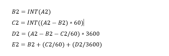
The original formula for one of the constants “P” is given as shown (1). If we enter the formula as prescribed in a hand calculator it will evaluate correctly but will not work correctly in Excel in this format. So we need to tell Excel to essentially divide everything in the top line by everything in the bottom by adding parenthesis as shown (2).

The bottom line shows the actual input in the excel formula bar (3).

We are continually working on updates to the Ordinate and Cad package so watch this space for new articles. There will also be in-depth tutorials on interrogating ordinate information to find max-width, tangents and matched second-degree curves as well as updates on detail drawings.

P-51 Ordinate & CAD

P-51 Ordinate & CAD Package: 

A comprehensive overview of the Ordinate/CAD package for the P-51 Mustang B,C and D aircraft. This package is the result of over 2 years of extensive research and development incorporating everything I know about the ordinate information pertinent to the P-51 Mustang; now available for download.

Fully Dimensioned Layout Drawings (Autocad 2d):

These are my CAD files that you can use for your own projects. These files are being made available for personal use only and not for commercial gain. Detailed layouts, fully dimensioned.

51j

engine mount revb

Tip 1: The Engine Mount drawing is a good starting point when setting out your CAD model. This will establish the fuselage datum points, Thrust line, Engine mount locations, and Firewall.

The dimensions for this have been triple checked. Incorporates information extrapolated from 6 different documents.

Tip2: Did you know you can work with inch and mm dimensions in the same model. If you happen to be using an mm template and wish to input inch dimensions then just type in the value followed by the unit type; either or in. So for 1 3/8in enter exactly as shown including space and vice versa if working in the inch template and using mm just quote mm units.

Over 228 Autocad 2D Point Profiles Derived from Spreadsheets:

These are my CAD files (DWG) that you can use for your own projects incorporating the point data. These files are being made available for personal use only and not for commercial gain. 2D profiles of all frames for wings and fuselage.Ordinate DWG profile

Ordinate Spreadsheets: 1000’s of Ordinate Point Coordinates (mm and inch):

These are my Excel spreadsheet files that you can use for your own projects. These files are being made available for personal use only and not for commercial gain. All ordinate points painstakingly entered by hand in both mm and inches. Data is sorted and extrapolated to derive 3d coordinates for direct input into most CAD systems.

Original Military Specs AN & MS (fair share) with Dimension Spreadsheets:

Standard specifications and dimensions for parts including turnbuckles, bolts, nuts washers etc. 3D CAD models of these parts are available separately as a collection; refer to the CAD library tab. Relevant parameters are recorded in spreadsheets that can link to CAD models.

2019-10-06_17-03-01The full Ordinate/CAD dataset will literally save you 100’s of hours of tedious work and is available online. For further information please send an email to hughtechnotes@gmail.com 

This Ordinate/CAD dataset is only available from my blog. All work and research were done by me. All spreadsheets and DWG files are fully editable.

Models on CGTrader:

Alongside the ordinate and dimensional research I also have a large number of professionally prepared 3D CAD models for the P-51 Mustang now available for download on CGTrader.These include the Tailwheel assembly for the P-51 Mustang. All parts, including all internal components, nuts, bolts, washers, and pins modeled to original standards. Tailwheel CAD assemblies on CgTrader:

P-51 Mustang TW Shock

exit These CAD models include fully itemized layouts for each assembly.se

As usual please get in touch at the following address for all inquires HughTechnotes@gmail.com 

NAA P-51D Mustang: Landing Gear Dims

NAA P-51D Mustang: Landing Gear Dims

I am currently working on the Landing Gear geometry dimensions to check the data for accuracy. During the course of this research, I thought it may be of interest to share some Excel formula for converting angles shown in Deg Min Sec to decimal degrees and vice versa.

p-51 Landing Gear

The plan angle for the OLEO Strut relative to 25% wing chord is 4° 32′ 35.14″ as shown in the above sketch which translates to 4.543094 degrees.

The accuracy of the angles and dimensions in the NAA documentation is rather good with small deviations occurring of only 0.003mm when developing this in CAD. I should note this deviation is negligible and for all intents and purposes can be ignored. However, I like to get this stuff right so I have set about developing the landing gear dimensions to be as close as possible to be exact.

As I have already developed the cad geometry I measured the same angle above from the CAD system which is now giving me 4.54309673 degrees.

In Excel:

excel table

Starting from the left; in column A; I have input the angle from the cad system, then systematically converted to Deg, Min, Sec in separate cells and then converted back to a decimal angle in column E.

The equations for each cell are as shown below:

p51 Landing gear eq

Just enter the equation in the cells denoted; so for the first equation, this would be in cell B2. The latter equation works fine without parenthesis, which I included just to keep the equation tidy.

The Landing gear geometry will be recorded in a separate spreadsheet and added to the P-51 Ordinate Package. Mustang P-51 Ordinates

P-51D LG

Mustang P-51 B/C Ordinates

Mustang P-51 B/C and P-51 D Ordinates:

P-51BC Layout

I have had a number of requests for the ordinate spreadsheets I developed for the Mustang P-51 B/C and D fuselage, cowl, cooler and air intakes, so I have decided to make them available to all; which could save you considerable time and effort.

The ordinates are listed on 10 separate Excel workbooks with 18 spreadsheets for all known ordinates from manufacturers data. The ordinate listings are in both mm and inches with the X,Y,Z coordinates extrapolated from this data-set for ease of transferring to a suitable CAD system. The total points listed are literally thousands.

P-51 D Layout102-00005: Fuselage (BC main)
102-00006: Fuselage (forward to cowl)
102-00007: Removable Scoop (fuselage, Int and Ext)
102-00008: Coolant Radiator Duct (Aft Section)
102-00008: Coolant Radiator Duct (Fwd Section)
102-00008: Oil Radiator Duct (Aft)
102-00009: Carb Air Scoop (Cowl)
106-00006: Wing (P-51D)
73-00006: Wing (P-51BC)
 
+ Autocad DWG Fuselage Frame & Wing Profiles P-51 B/C and P-51D (ref only)
NAA Master Dimensions Report (wings, fuselage, landing gear).
Include scans of original source documents for reference.
 
The spreadsheets are not locked or protected so you can manipulate the core data to suit your own applications.
The P-51D fuselage profiles are reference only due to being mathematically generated based on original NAA methods and thus are not verified.

This represents a huge number of hours worked, meticulously listing each ordinate individually and then creating cad drawings to check the ordinates and derive the ordinates that are unclear on the manufacturers’ drawings.

2016-06-04_23-33-26

The ordinates for the P-51D wings comprises 2 sheets; the first listing the tabulated data as per the original manufacturer drawing and the second extrapolated to compile the X,Y,Z coordinates for input into CAD.

P-51D WING ORDINATE

P-51 Wing Profiles

Update 20 Aug 2019:

The spreadsheets now include the OLEO undercarriage and general tidy up of datasheets for consistency. Now probably the most comprehensive and complete dimensional study of the P-51 B/C and D. 2018-09-20_22-45-40

Horizontal Stabiliser and Fillet Ordinates layout:

Mustang P-51 BC

Sample data for P–51B/C and P-51D;

For further details see this more descriptive post or send me an email to HughTechnotes@gmail.com