Technote: Complex Surface Hole Location

Technote: Positioning Holes in Complex Surfaces

When detailing the skin panels for aircraft it can be quite daunting trying to locate a series of holes accurately at a specified distance from the edge of the panel. Typically fillets to wings and horizontal stabilizers and transition pieces to vertical stabilizers are all complex surfaces.

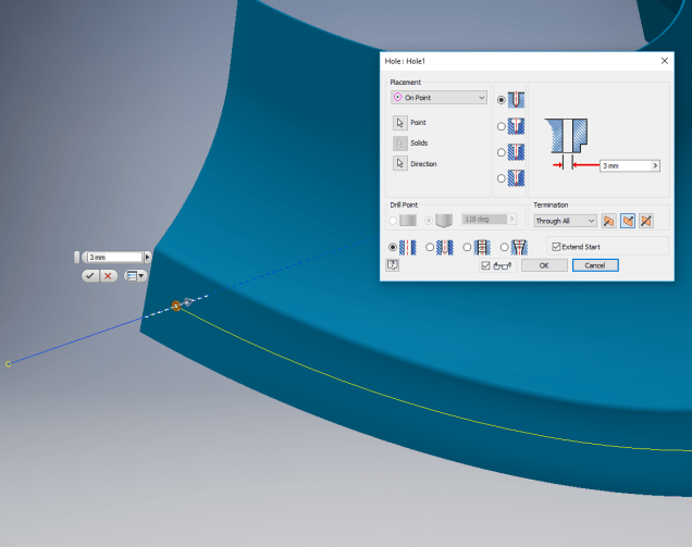
In this example, we need a series of holes located 17.5 mm from the top and bottom edges. As you can see the surface at the top and the flange angle at the base varies.

The location of the first hole, top and bottom, is aligned vertically so we first create a workplane to determine the horizontal position of the first hole. Ultimately we will use a 3d intersection curve for the centre line of the holes which must first be determined by sweeping a circle profile sketch along the edge as a surface with the radius set to the required edge distance. Using a circular profile for the sweep ensures that any intersection point on the surface will be at the specified edge distance.

This swept surface is then trimmed to the first work plane to define the start point of the 3d surface intersection curve as shown.

The resulting 3d spline represents the line of the hole centres at 17.5mm from any point along the edge of the fillet.

We then apply a point and an axis (perpendicular to the surface) at this point to determine the hole direction. I suspect because it is not a regular surface the hole feature will not allow me to select the surface for direction. Use “Extend Start” when creating hole.

2017-07-11_10-03-21

To pattern the hole along the spline and be perpendicular to the surface create the array as shown below. Be sure to select the extended options for “Direction 1” and “Adjust”.

2017-07-11_10-04-34

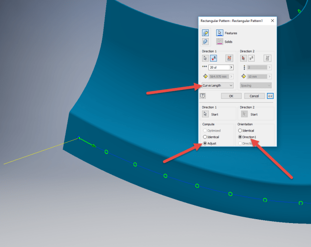
Do the same for the top array of holes, resulting in 2 sets of holes aligned with the surface at 17.5 mm from the edge.

2017-07-11_10-07-10

This works for the vast majority of riveted panel connections where locally there is a degreee of flatness between the matching parts. In instances, where there is extreme curvature of the connecting faces the radius of the extruded circle would have to be adjusted accordingly.

Grumman F6F Hellcat: Ordinates

Grumman F6F Hellcat: Ordinates

I am without access to a Cad system for a few weeks so I decided to spend time reviewing my archive collection. Whilst looking through the many aircraft in the archives I came across some interesting information for the Grumman F6F Hellcat.

F6F-3_Hellcat_11_of_VF-2_on_the_catapult_on_board_the_carrier_USS_Hornet_CV-12_May_6_1944

The archive consists of a substantial number of the Grumman drawings, varying in quality from very good to very poor, though I should clarify the latter relates to only a small number of drawings. This archive includes ordinate tables for the wings and fuselage so I figured it might be a worthwhile project to attempt to decipher and create a set of ordinate spreadsheets as I have done previously for the Mustang P-51.

Hellcat ordinates

Though I rather like this aircraft it was not a priority project on my to-do-list, but having spent today studying the Grumman drawings this could turn out to be a rather challenging project.

Fuselage Work in progress:

hellcat ords 2

Update:

hellcat prelim 2
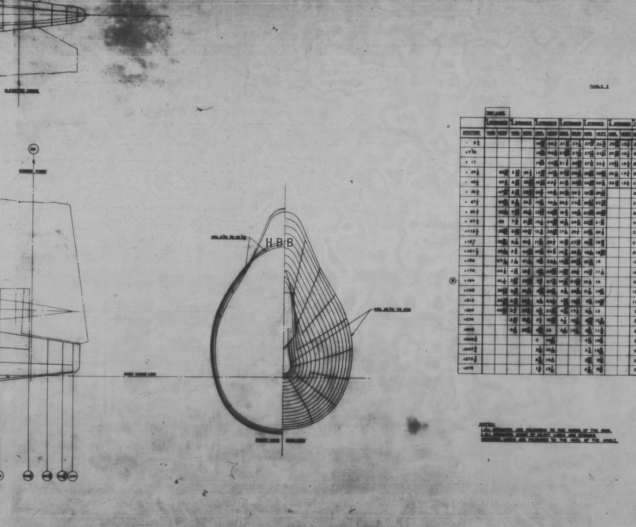
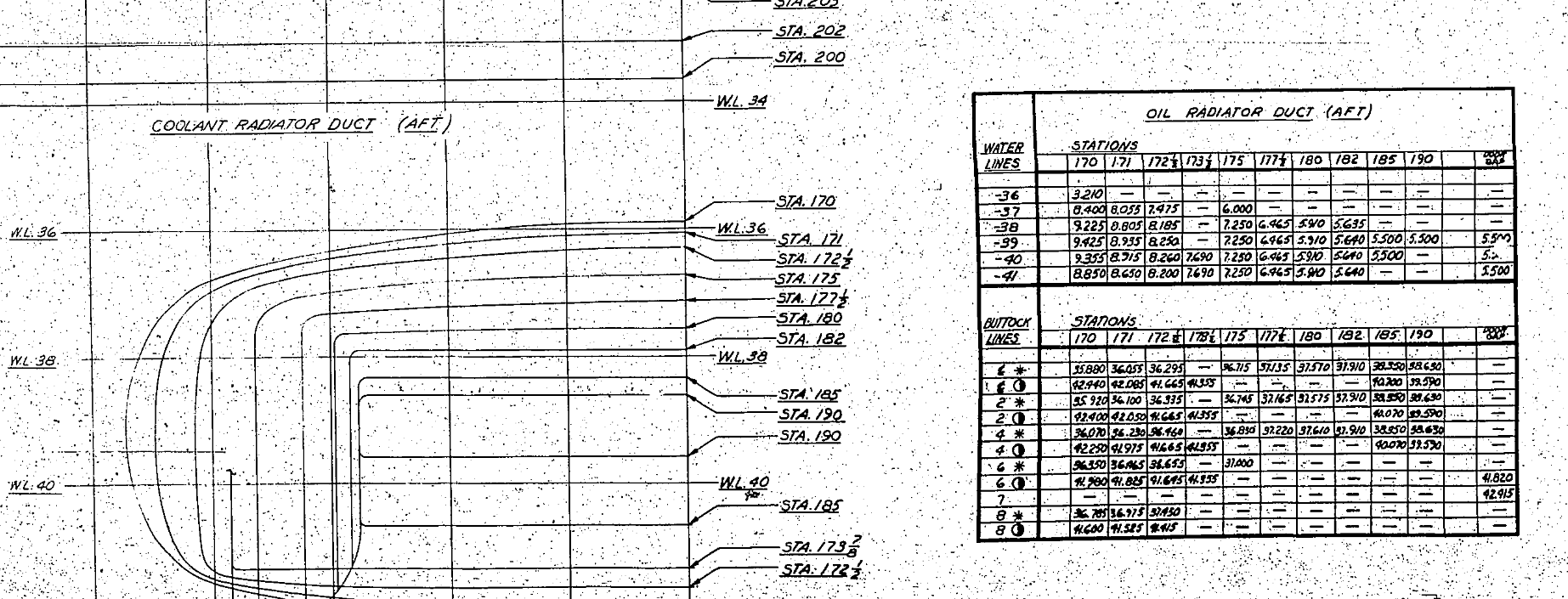
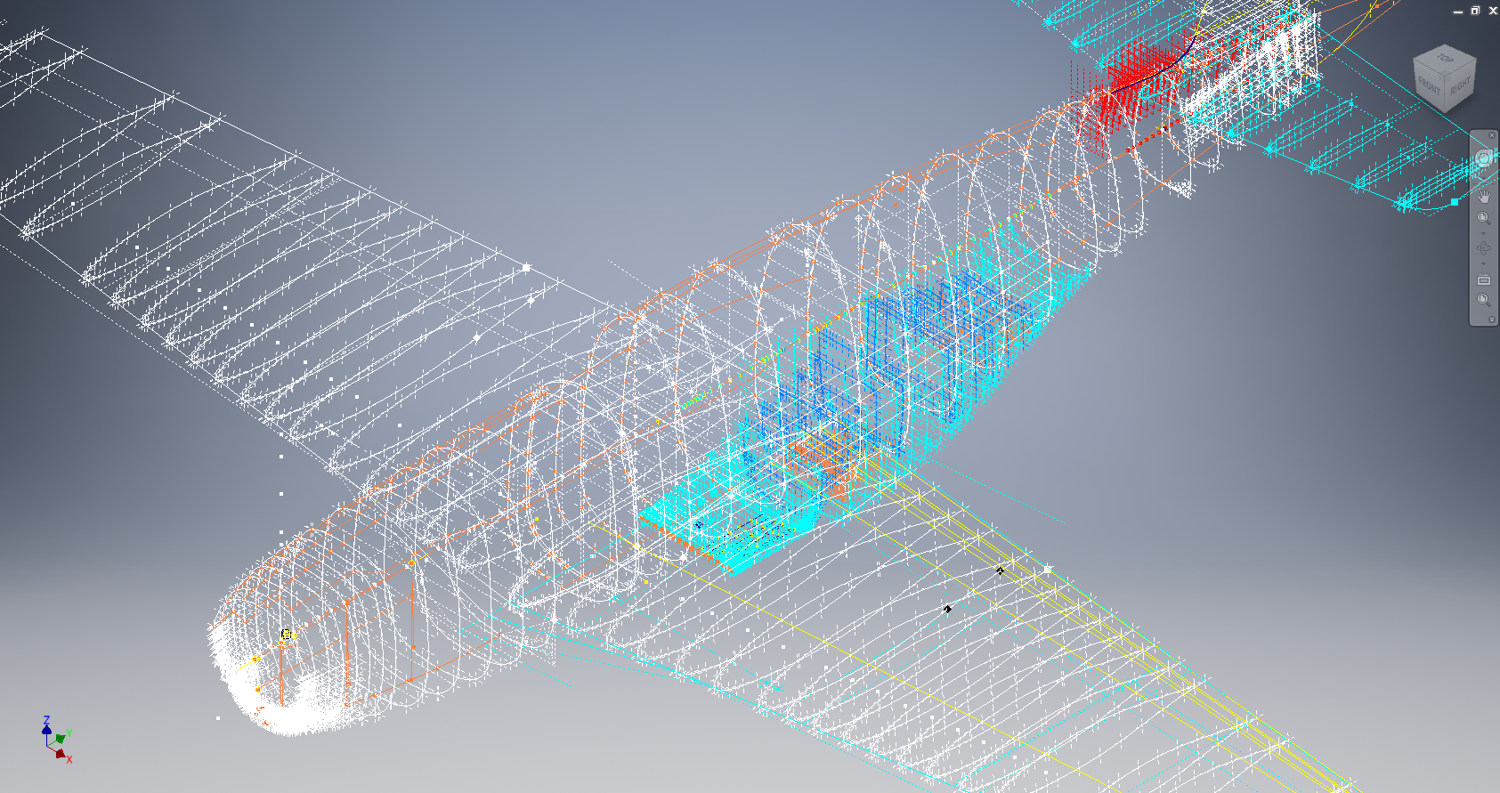
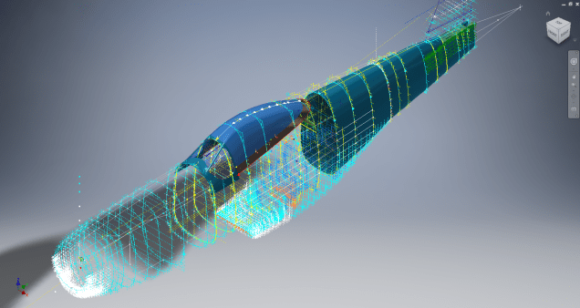
I have managed to obtain a trial copy of the Inventor LT so I can now move ahead with this project. This first interpretation of the fuselage profiles is actually not bad at all. A few macro adjustments will be required to get the profiles correct, mainly due to the quality of the archive where roughly 10% of the values are very difficult to read.

Each point represents the ordinate of the longitudinal stringers which I will profile to assess the alignment and curvature as an aid to finalizing the frame ordinates. Perfecting the frame ordinates can become quite tricky at this stage, requiring constant referencing of the original drawings including the frame structures themselves which often provide additional information that can assist with this process.

NAA P-51D: Master Lines Plan

NAA P-51D Mustang: Master Lines Plan

The P-51D project is progressing well with further developments on the fuselage frame profiles. I now have a comprehensive Master Lines Plan incorporating additional information obtained from mathematical analysis, drawings, reference documentation and geometric developments. I have updated and remodeled the underside Oil Cooler Air intakes, canopy, windshield, rear fuselage and fuselage tail-end. As part of the remodel the groups of ordinates for each frame for the Oil Radiator Duct, Coolant radiator Duct and Removable Scoop are now contained on their own respective work-planes. This will make it much easier to micro manage the final mold lines.

Fuselage Master Lines Plan (P-51D overlaid on P-51 B/C):

2017-07-01_14-32-09

Test Lofts and developments:

2017-07-01_14-30-24

Front Views (note the Canopy Profile update from the previous article):


A month ago I was not sure how much could be achieved given the limited amount of information at hand but with due diligence and detailed research, it is quite amazing what can be accomplished.

With this template, it is now technically possible to accurately develop a CAD model for the entire fuselage structure and mechanical components for the P-51D, which would be great; but I often wonder what the value of such an undertaking would achieve, other than being a darn interesting thing to do and a test of CAD modeling skills.

Having achieved this significant milestone the time is right to conclude the work on the Mustang P-51D and P-51 B/C projects. I may continue with the P-39 project but as always I am keen to explore the options for the more obscure extinct aircraft as described in Operation Ark.

2017-07-01_00-15-20

If you are planning on developing your own Master Lines plan a good place to start would be with the 1000’s of ordinates points cataloged and recorded on the spreadsheets here: Mustang P-51B/C Ordinates which also includes the wing ordinates for the P-51D and vertical stabilizer.

NAA P-51D Mustang: Wing Ordinate Rev

NAA P-51D & B/C Mustang: Wing Ordinate Major Update:

Thanks to Roland Hallam, I am now in receipt of new verifiable information that has prompted a return to the P51 project and a major update to the wing ordinate data sheets.

2017-05-21_15-46-57

Many of the blanks have now been filled in and new additional information added. The above image is a snapshot of the work in progress. The groups highlighted in blue are checked verified dimensions, the red values are those that have changed and those areas remaining in white have prompted an interesting conclusion. Up until now, it was presumed that the wing profiles for the P51D and P51C were the same with the exception of the wing root, however, closer inspection would now suggest that a few rib locations are also slightly different which requires further investigation.

I am still working through the new information and dissecting what is relevant to the P-51D and the P-51B/C variants. This will probably take me a while to evaluate but I am confident that this will result in the most comprehensive dataset yet compiled for the P-51 wings.

I had not expected to return to the P51 project at this time but I’m sure you will agree this is an exciting development.

Sopwith Pup:Wing Brackets

SopwithPup: Wing Brackets

This was not meant to have been a study in its own right, but out of curiosity I couldn’t help but wonder if there was enough information to actually build an accurate 3D model.

I was also curious why I had received a number of help request emails from my friend about this particular aircraft…so I decided to have a closer look. His latest query was regarding brackets similar to the one I mentioned in my previous post but specifically the centre section connecting brackets to the wings.

The left bracket belongs to the centre section and the right bracket is the connecting bracket for the wing that slots into the centre section bracket.

sp-009

The bracket dimensions are such that the centre bracket sits proud off the centre spar whilst the wing bracket is embedded in the wing spar, so technically they should just fit into one another without too much problem!! That’s the theory but the reality is it doesn’t quite align with expectations.

sp-03

This image shows the actual clear dimensions within the top and bottom rib flanges which replicate the perimeter dimensions of the wooden centre spar. In order for the centre section bracket to connect to the spar we would have to notch the top and bottom rib flanges to get it to fit. The horizontal dimension can vary (highlighted) but we will be restricted by the vertical dimension. I can’t imagine why anyone would want to notch the top and bottom flanges as this diminishes its strength. Plus there’s another issue with this…

sopwith-pup06

This preliminary model shows the problem where the centre spar is actually set back one inch to facilitate the incoming connecting bracket from the main wing. Ideally, we need to fully assemble the centre section and have it fitted to the aircraft and aligned prior to fitting the wings, but how can this be done if we can’t screw the rib flanges to the spar? I think in this instance I would shape the wooden spars in such a manner as to facilitate fitting of the flanges and mating with the wing spars.

I have done some research on this and it appears to be a known issue with some clever blokes just redesigning the connectors to make it work better or tapering the wing spar to good effect as shown below.

sdasmpup

It looks as though the wing spar is tapered with a smaller bracket sized to fit within the centre bracket. That would work and likely an improvement implemented in the workshop. A very rough preliminary study could look something like this…

…it does need a lot more work but I don’t have a lot of time to develop it further right now!

The design in many respects seems a little rough and ready, but we have to remember in those days they were under a huge amount of pressure to get these aircraft built and get them into the field. The life expectancy of these aircraft was only six weeks so replacements had to be shipped out in rather a quick time.

No disrespect either to Tom Sopwith and his engineers, these things actually flew rather well regardless of the vagaries of the design and what may seem to be annoyances to us may well be things they would naturally deal with in the workshop without any hassle.

It is very tempting to continue developing the Sopwith Pup but to do so efficiently would require setting out the basic geometry for the entire aircraft, identifying the anomalies and determining suitable resolutions as close as possible to the original design intent. I’m not sure I have the time nor the inclination to do so.

This has been a welcome distraction from the P-39 Airacobra project and will likely feature in a few more posts as I will surely continue to receive help requests from my good friend.

Mustang P-51 B/C Ordinates

Mustang P-51 B/C and P-51 D Ordinates:

P-51BC Layout

I have had a number of requests for the ordinate spreadsheets I developed for the Mustang P-51 B/C and D fuselage, cowl, cooler and air intakes, so I have decided to make them available to all; which could save you considerable time and effort.

The ordinates are listed on 10 separate Excel workbooks with 18 spreadsheets for all known ordinates from manufacturers data. The ordinate listings are in both mm and inches with the X,Y,Z coordinates extrapolated from this data-set for ease of transferring to a suitable CAD system. The total points listed are literally thousands.

P-51 D Layout102-00005: Fuselage (BC main)
102-00006: Fuselage (forward to cowl)
102-00007: Removable Scoop (fuselage, Int and Ext)
102-00008: Coolant Radiator Duct (Aft Section)
102-00008: Coolant Radiator Duct (Fwd Section)
102-00008: Oil Radiator Duct (Aft)
102-00009: Carb Air Scoop (Cowl)
106-00006: Wing (P-51D)
73-00006: Wing (P-51BC)
 
+ Autocad DWG Fuselage Frame & Wing Profiles P-51 B/C and P-51D (ref only)
NAA Master Dimensions Report (wings, fuselage, landing gear).
Include scans of original source documents for reference.
 
The spreadsheets are not locked or protected so you can manipulate the core data to suit your own applications.
The P-51D fuselage profiles are reference only due to being mathematically generated based on original NAA methods and thus are not verified.

This represents a huge number of hours worked, meticulously listing each ordinate individually and then creating cad drawings to check the ordinates and derive the ordinates that are unclear on the manufacturers’ drawings.

2016-06-04_23-33-26

The ordinates for the P-51D wings comprises 2 sheets; the first listing the tabulated data as per the original manufacturer drawing and the second extrapolated to compile the X,Y,Z coordinates for input into CAD.

P-51D WING ORDINATE

P-51 Wing Profiles

Update 20 Aug 2019:

The spreadsheets now include the OLEO undercarriage and general tidy up of datasheets for consistency. Now probably the most comprehensive and complete dimensional study of the P-51 B/C and D. 2018-09-20_22-45-40

Horizontal Stabiliser and Fillet Ordinates layout:

Mustang P-51 BC

Sample data for P–51B/C and P-51D;

For further details see this more descriptive post or send me an email to HughTechnotes@gmail.com