P-51 Ordinate & CAD Package:
A comprehensive overview of the Ordinate/CAD package for the P-51 Mustang B,C and D aircraft. This package is the result of over 2 years of extensive research and development incorporating everything I know about the ordinate information pertinent to the P-51 Mustang; now available for download.
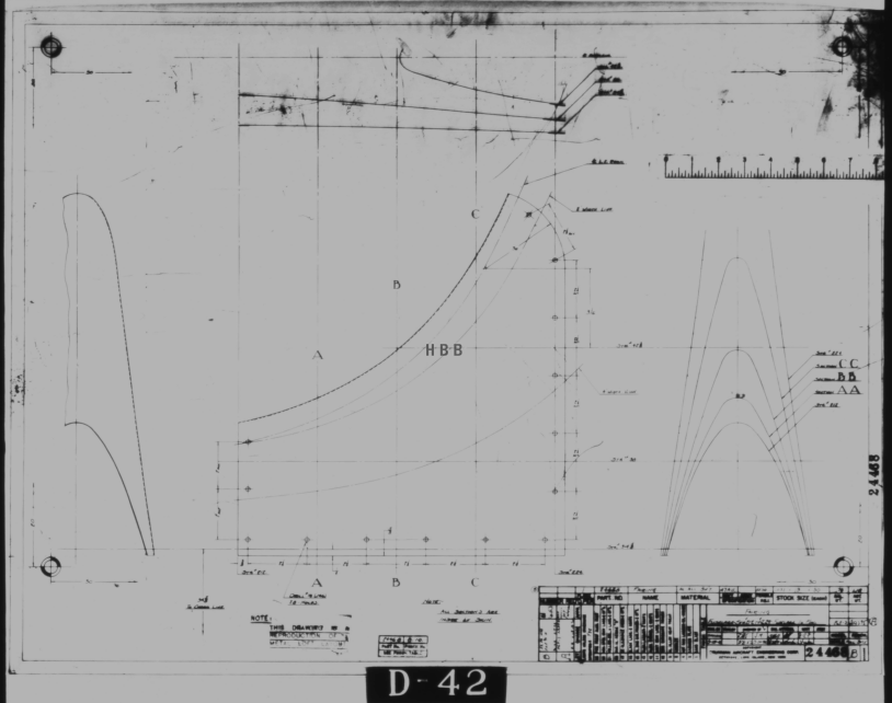
Fully Dimensioned Layout Drawings (Autocad 2d):
These are my CAD files that you can use for your own projects. These files are being made available for personal use only and not for commercial gain. Detailed layouts, fully dimensioned.


Tip 1: The Engine Mount drawing is a good starting point when setting out your CAD model. This will establish the fuselage datum points, Thrust line, Engine mount locations, and Firewall.
The dimensions for this have been triple checked. Incorporates information extrapolated from 6 different documents.
Tip2: Did you know you can work with inch and mm dimensions in the same model. If you happen to be using an mm template and wish to input inch dimensions then just type in the value followed by the unit type; either “ or in. So for 1 3/8in enter exactly as shown including space and vice versa if working in the inch template and using mm just quote mm units.
Over 228 Autocad 2D Point Profiles Derived from Spreadsheets:
These are my CAD files (DWG) that you can use for your own projects incorporating the point data. These files are being made available for personal use only and not for commercial gain. 2D profiles of all frames for wings and fuselage.
Ordinate Spreadsheets: 1000’s of Ordinate Point Coordinates (mm and inch):
These are my Excel spreadsheet files that you can use for your own projects. These files are being made available for personal use only and not for commercial gain. All ordinate points painstakingly entered by hand in both mm and inches. Data is sorted and extrapolated to derive 3d coordinates for direct input into most CAD systems.


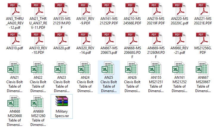
Original Military Specs AN & MS (fair share) with Dimension Spreadsheets:
Standard specifications and dimensions for parts including turnbuckles, bolts, nuts washers etc. 3D CAD models of these parts are available separately as a collection; refer to the CAD library tab. Relevant parameters are recorded in spreadsheets that can link to CAD models.
 The full Ordinate/CAD dataset will literally save you 100’s of hours of tedious work and is available online. For further information please send an email to hughtechnotes@gmail.com
This Ordinate/CAD dataset is only available from my blog. All work and research were done by me. All spreadsheets and DWG files are fully editable.
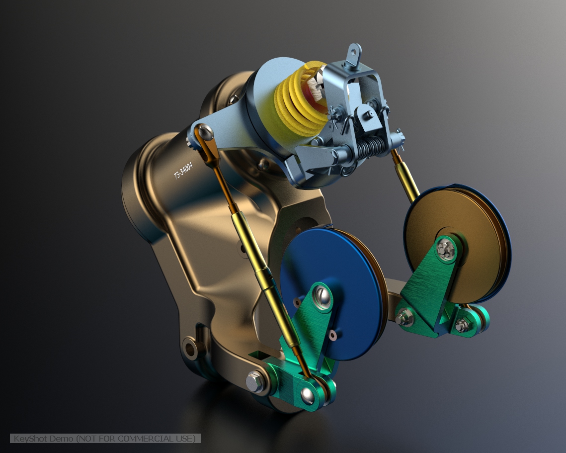
Models on CGTrader:
Alongside the ordinate and dimensional research I also have a large number of professionally prepared 3D CAD models for the P-51 Mustang now available for download on CGTrader.These include the Tailwheel assembly for the P-51 Mustang. All parts, including all internal components, nuts, bolts, washers, and pins modeled to original standards. Tailwheel CAD assemblies on CgTrader:


exit These CAD models include fully itemized layouts for each assembly.se


As usual please get in touch at the following address for all inquires HughTechnotes@gmail.com