For quick renderings that are perfect for blog posts, I typically prefer KeyShot. It provides an intuitive workflow and a large library of environments and materials. However, the trial version has some limitations: you cannot save projects or export a rendered image, except as a screenshot. When I was recently asked to produce high-quality renders of the Republic JB2 for a museum display, I was uncertain about how to accomplish this.
These products are very expensive and far exceed my budget, so I urgently needed to find a solution. That’s when I discovered Autodesk VRED. I downloaded the software along with the accompanying asset library, and to my surprise, the trial version is fully functional. It allows me to save projects and create high-resolution renders, and it runs for 30 days.
Autodesk Vred retails at around $14000, which is extraordinarily expensive, but it is aimed primarily at the Automotive industry. Consequently, the product is packed full of features and limitless options on environments, materials, lighting and camera setups. It truly is a comprehensive and, to some degree, rather complex product, so there is a steep learning curve.
Undeterred, I set to work by reviewing tutorials, YouTube videos, and various online resources. Over the course of six days, I gained a deeper understanding of the nuances of VRED rendering. While I’m not an expert yet, the test renders started to come together, culminating in the images showcased below.
These images are not final, as I still need to work on the texture mapping and apply materials to some internal components. However, they demonstrate that it is possible to achieve satisfactory results in a relatively short time. Although the product has a steep learning curve, it encourages you to deepen your understanding of materials, textures, and lighting, which ultimately enhances your grasp of rendering processes.
I highly recommend that anyone interested in creating renders try Autodesk VRED. It offers the full functionality of a high-end rendering product, including the ability to save your projects and export high-resolution renders. The availability of a 30-day trial version is exceptional—Keyshot, take note!
I want to clarify that I have no affiliation with Autodesk, but when it comes to the accessibility of professional products, Autodesk is unparalleled. I have no problems recommending worthwhile products, like this one.
This project aims to document and preserve dimensional data for historical aircraft, currently working on models such as the P-47, FM2, and Grumman Goose, alongside two glider projects. Utilizing archival blueprints—often of suboptimal quality—we employ precise digital reconstruction techniques to ensure the accuracy of aircraft structural data. The goal is to support restoration efforts, research, and educational initiatives in aviation history.
3. Objectives:
Digitally reconstruct and verify the dimensional data of historic aircraft.
Provide comprehensive documentation for restoration, museum displays, and aerospace research.
Develop methodologies for extracting accurate data from degraded blueprints.
Expand the available reference library for aviation researchers and engineers.
4. Significance & Impact:
Historical Preservation: Ensures that legacy aircraft remain accurately documented for future generations.
Educational Contribution: Supports aerospace research institutions and museums with validated technical data.
Collection and analysis of historical blueprints and microfilm archives.
Use of CAD software to recreate accurate aircraft structures.
Cross-referencing archival data with existing dimensional records.
Collaboration with restoration experts to validate findings.
6. Challenges & Solutions:
Suboptimal Blueprint Quality: Implement specialized image enhancement and measurement techniques.
Funding Limitations: Seek partnerships with aviation museums, historical organizations, and aerospace institutions.
Data Validation: Engage with experts to cross-check reconstructed aircraft dimensions.
7. Funding Request & Justification:
The project has been independently funded to date, but rising operational costs present financial challenges. Support is requested to sustain ongoing research, enhance documentation quality, and facilitate broader distribution to historical and aviation institutions.
8. Potential Collaborations & Sponsorships:
Aviation Museums: Partnerships for data preservation and restoration projects.
Educational Institutions: Opportunities for research integration and student engagement.
Aerospace Industry Experts: Validation and application of documented data.
Fellow Enthusiasts and Donors: Acknowledge contributions, engage in peer-to-peer discussion and provide technical support where applicable.
9. Conclusion:
This initiative offers a critical contribution to aviation history by preserving precise structural data of historical aircraft. With adequate funding and institutional partnerships, the project will continue advancing research and documentation efforts for aviation scholars and engineers.
—————————————————————————————————
Contact Hugh Thomson via email: hughtechnotes@gmail.com.
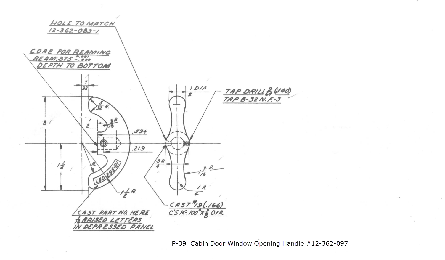
This little part at first glance seems fairly straightforward, but there are a few caveats.
It has been a while since I specifically wrote a CAD solution Technote, and this seemed to be an ideal subject for surface modeling and 3D sketching. The dimensions define the outline for the front view, which is fine, and the plan view, which details a thinning of the handle cross section.
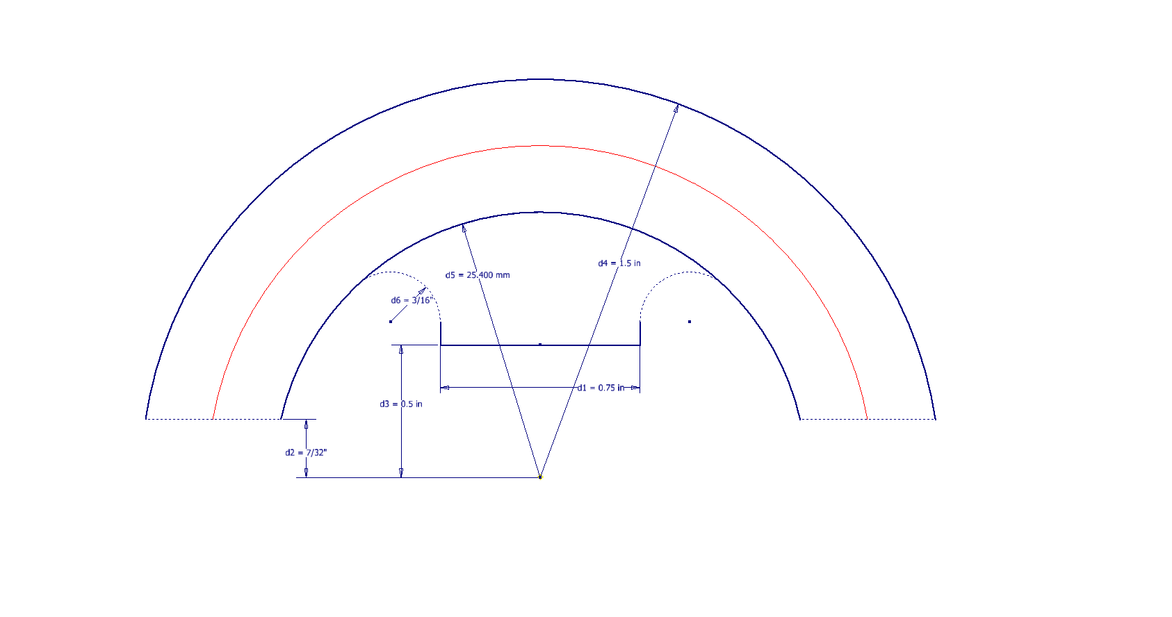
The thinning of the handle occurs in a specific plane as indicated in the plan view, while the front view maintains a consistent full depth diameter. Before diving into the modeling process, it’s important to pause and consider how to approach this design. Typically, my first step involves sketching out what is already known, which helps clarify the information we still need to gather. This initial sketching phase is crucial for laying the groundwork for an effective modeling strategy.
In each case, you’ll notice that these profiles are not closed. The base lines shown in the front view are defined as construction lines, and the end curves in the plan view are also intentional. This design choice allows the main profile lines to be used later for creating a Loft and for selecting a 3D Sketch Intersection. The center line of the arc in the front view will serve as the second selection for this 3D sketch. Additionally, note that the curves in the plan view are elliptical.
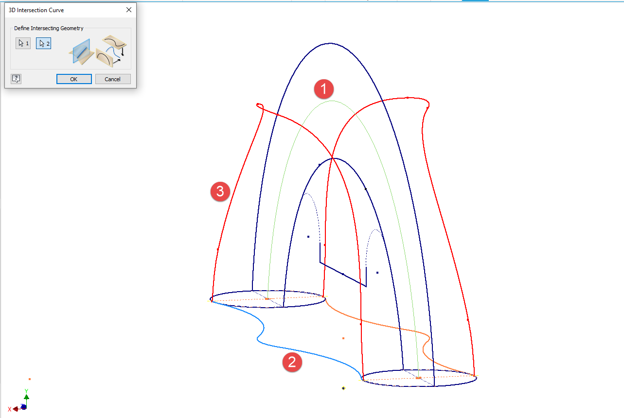
The purpose of the 3D Intersection sketch is to define guidelines for the eventual loft. Using the 3D sketch feature, we first select the center line from the front view and one curved edge from the plan view sketch. The resulting intersection will serve as the 3D path for the loft. This process needs to be repeated for both sides of the handle. The ellipses that will form the ends of the loft are created in a separate sketch from the previously mentioned plan view. This keeps them as distinct entities.
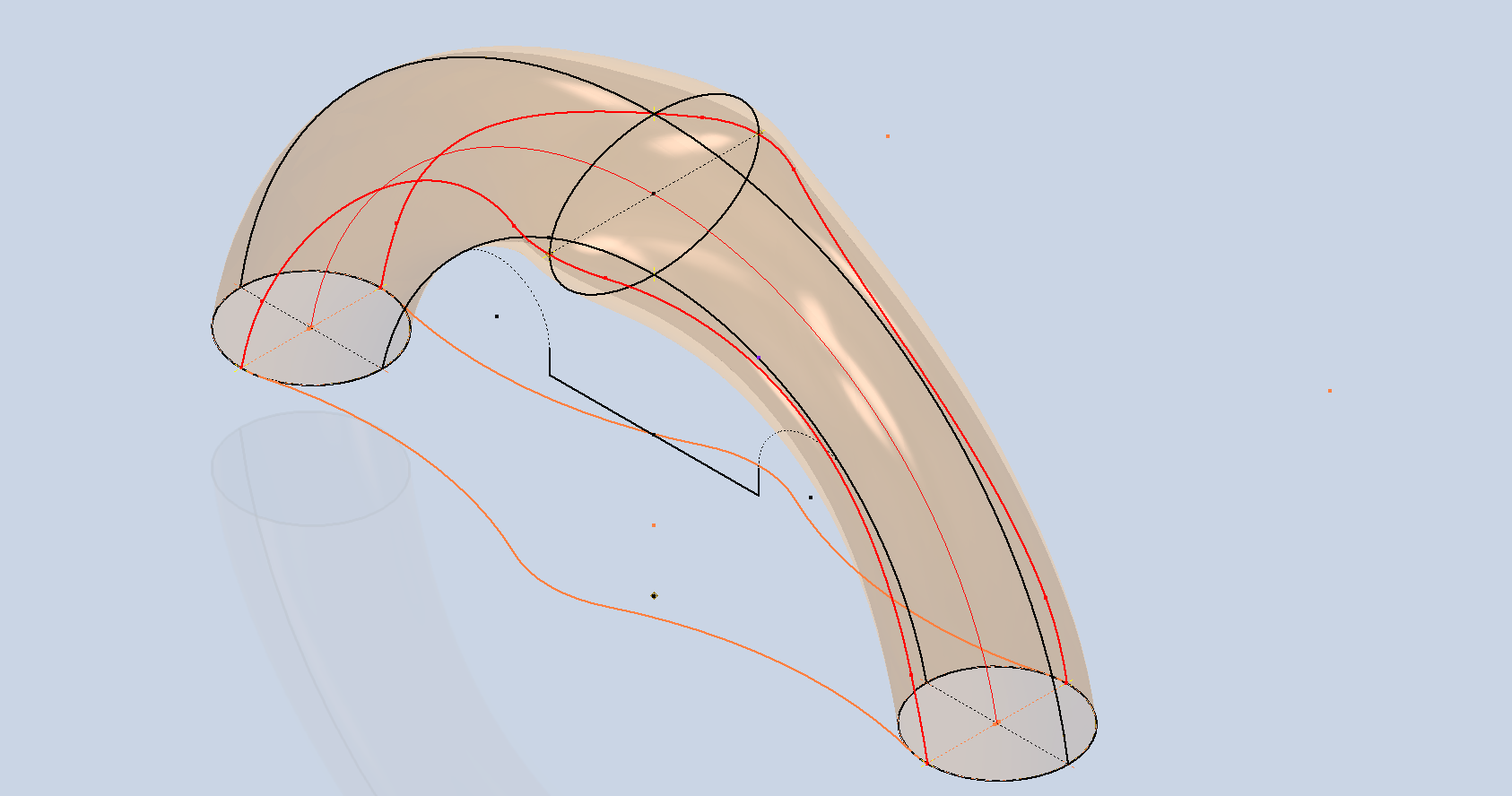
Hold on a moment; where did the ellipse in the middle of the arch come from? If we simply loft the two end profiles of the arch, as shown earlier, we can create an acceptable model, but it won’t be ideal. In the second image, where both surfaces are overlaid, you can see that this approach tends to create a diamond-like cross-section in the center. While this is not entirely incorrect, incorporating the ellipse in the center of the arch results in a much better finished surface, ensuring good continuity, as demonstrated.
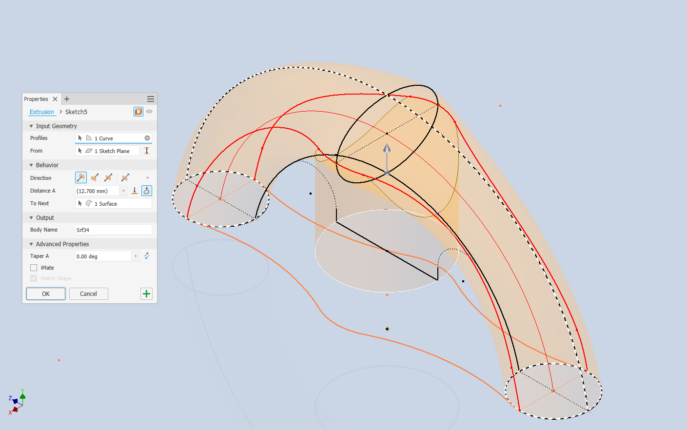
Once we have the arch lofted surface, we extrude the centre section circle to match the surface contours.
We then use this extrusion to trim the underside of the arch surface, apply patch surfaces to fill in the ends of the arch and this centre section. Then stitch everything together and we have the main solid model.
Apply a fillet as shown to the underside; note the fillet in this case is better selected as a tangent fillet and not a G2 curvature. It is often tempting to overuse the G2 fillet option as the perceived notion is that it creates a smoother finish, which by the way is correct, though in a case like this it tends to sharpen the fillet corners which is not good. Something to watch out for when applying fillets.
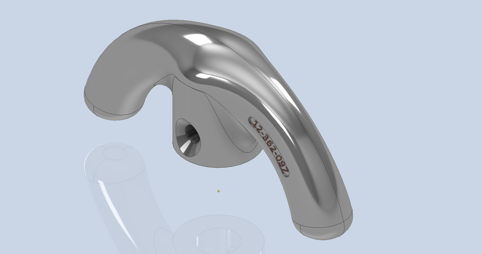
To finish up we add the holes as specified, fillet the ends of the arch (a good opportunity for a G2 fillet) and add the part identifier. The final part should look something like this:
In summary, when developing surface models, it’s beneficial to explore your options and start by creating sketches that support your plan of action. Consider using 3D intersections to define loft paths, and incorporate additional geometry as needed to maintain the circularity and continuity of the final surface.
This part is ready for manufacturing, which will probably be 3D printed for this static display restoration.
Typical Design Workflow:
Usually I would initially receive an inquiry via email from companies like Planes of Fame for a 3D CAD model of a specific part or assembly. Typically, the request includes a brief description of what is needed and not necessarily the actual part number. In this instance, it was for “the handle for operating the window glass.” I then searched through my archives to locate this item, reviewed the part’s blueprint, and checked which parts or assemblies it connects to ensure I have all the relevant information.
I will make every effort to start working on the CAD model as soon as possible, regardless of the time of day, to minimize any delays. For example, I received an inquiry about a part at 9:17 PM last night for the “P-39 Throttle Control Mount.” Following the established procedure, I was able to begin working on it relatively quickly on a Friday evening. The finished part (#12-631-027) was completed and submitted on Saturday at 11:17 AM. The final design included both the original 3D CAD model and a fully dimensioned 2D drawing, which is essential for verifying that all dimensions conform to the original blueprint.
This part will likely be 3D printed for the restoration of the static display, so the 2D drawing serves both as a dimensional check and a reference for manufacturing. If the inquiry had required a metal casting manufacturing process, the drawing would include more detailed information about part machining and the tolerances necessary for a full-metal manufactured item.
If you’re looking to bring your ideas to life with accurate 3D and 2D CAD models for replica parts, I would love to help! Don’t hesitate to get in touch hughtechnotes@gmail.com