NAA P-51D Mustang: Tail Wheel Housing
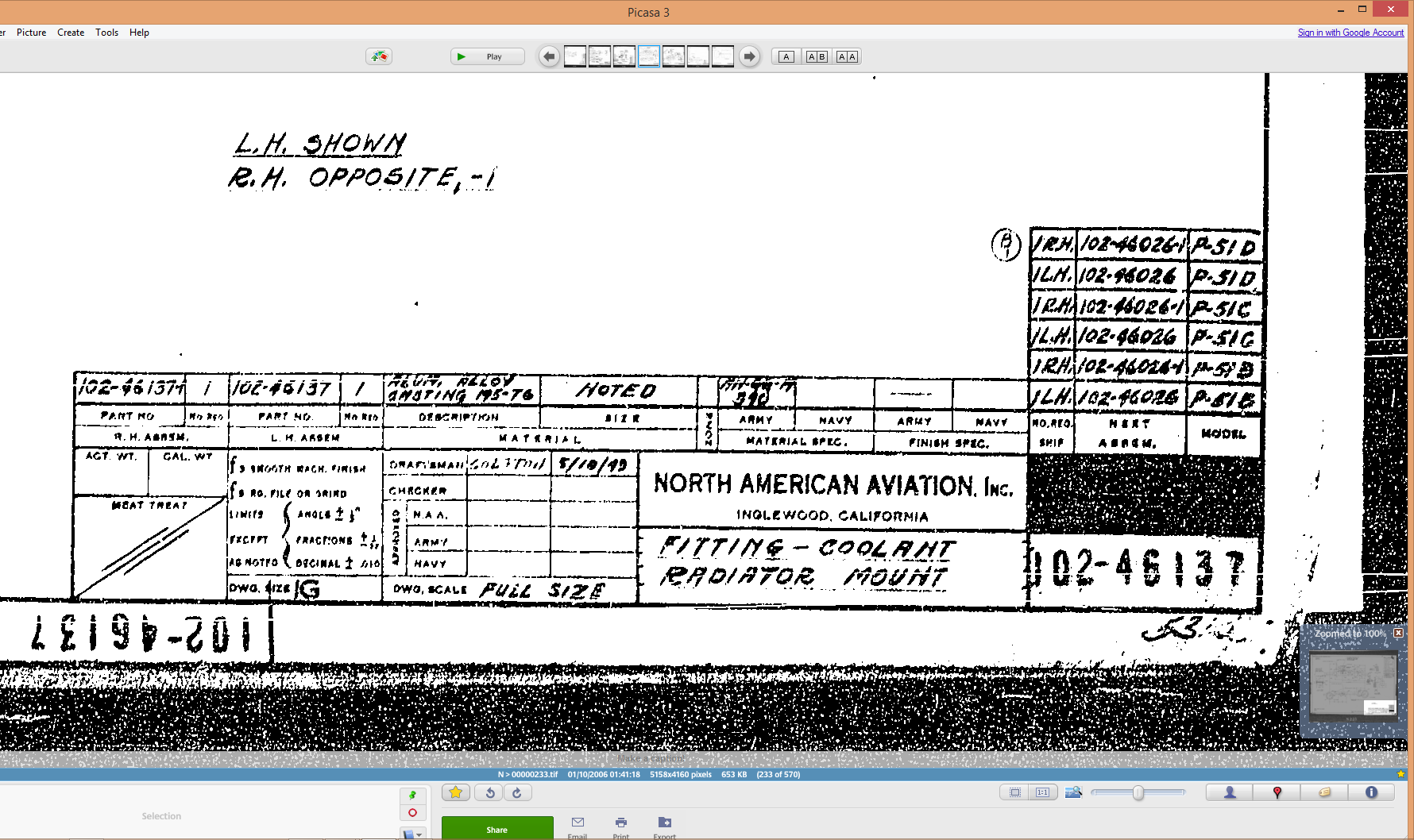
In my endeavors to develop the assembly and parts register I have made some progress determining the associations in conjunction with the listing in the NAA documents. I have started with the Tail Wheel assembly,which actually has 59 drawings for the sub assemblies and parts…it was surprising the number of drawings just for this one area!
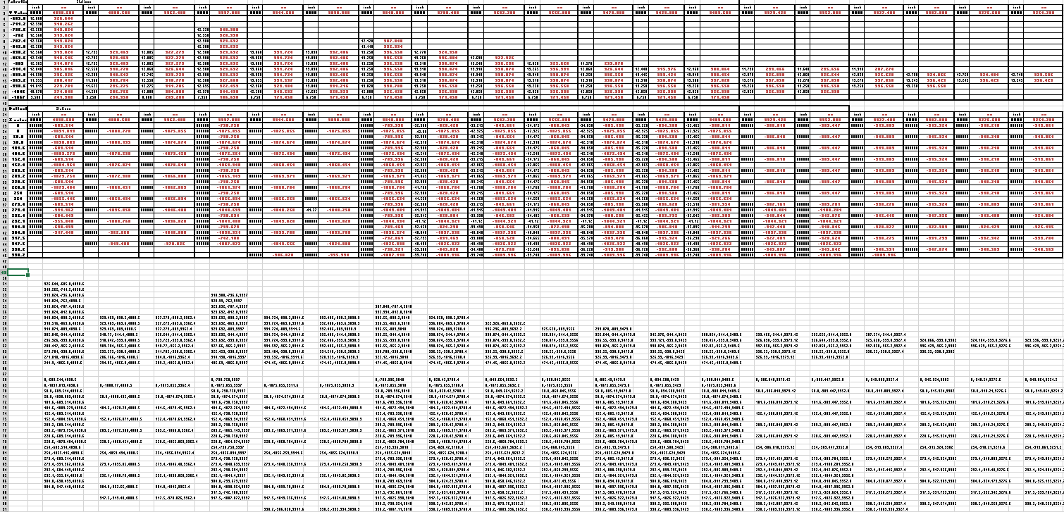
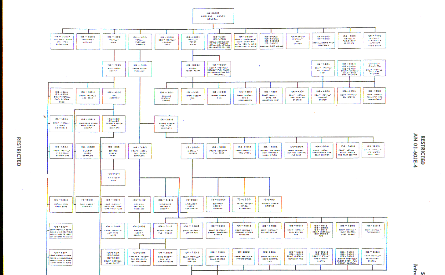
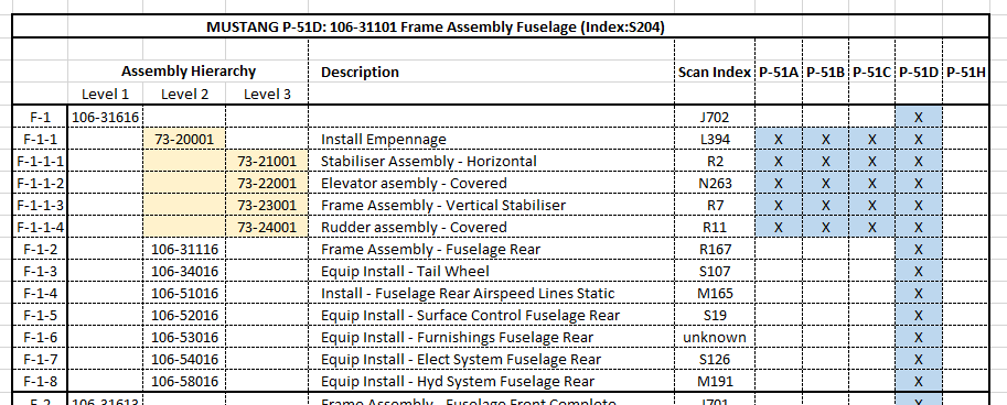
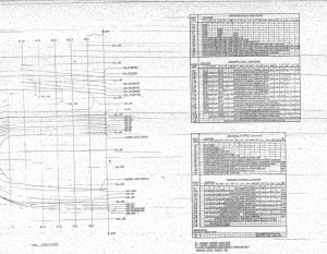
 This is a partial screen shot of the assembly register; again divided by sub-assembly level down to the individual parts.
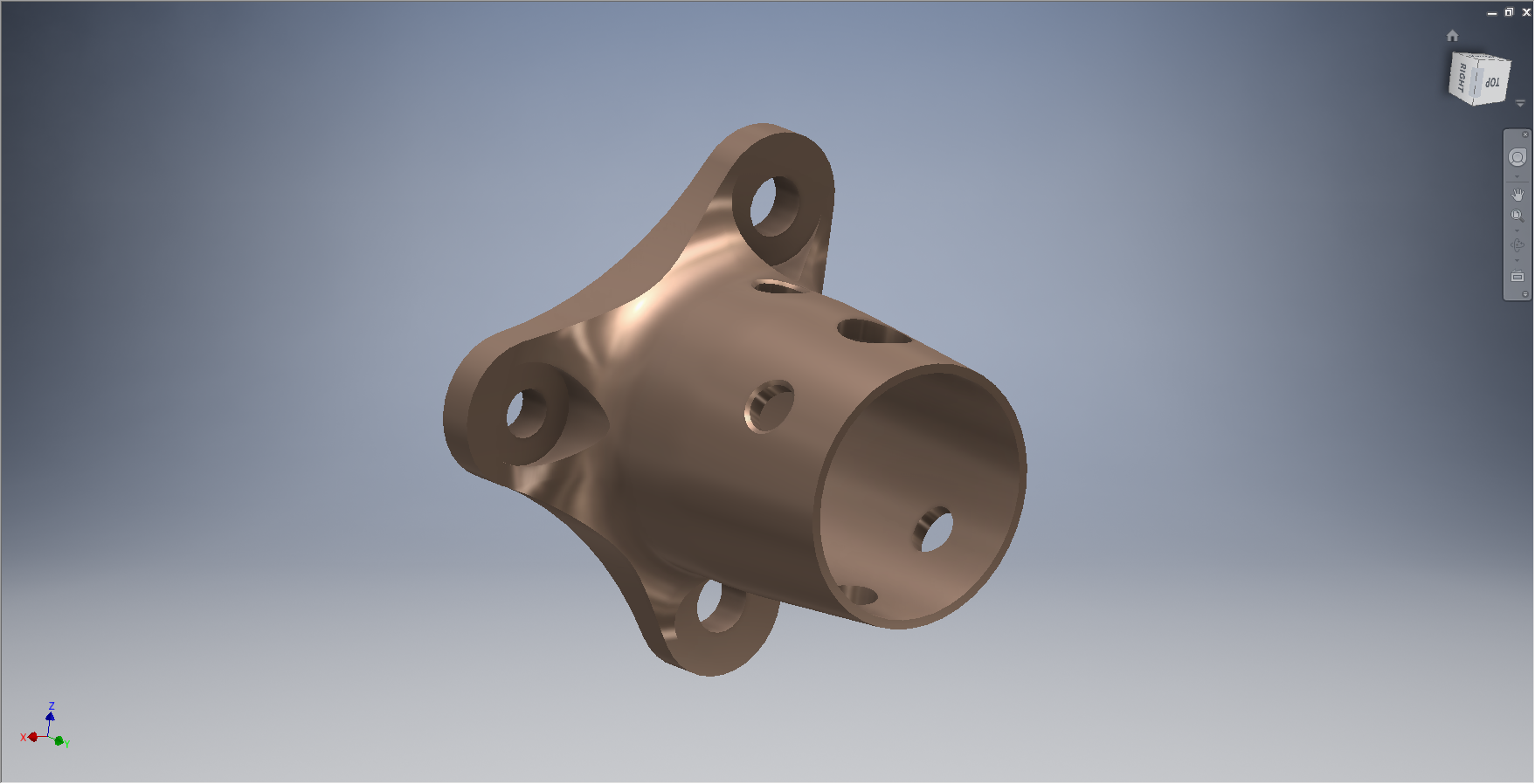
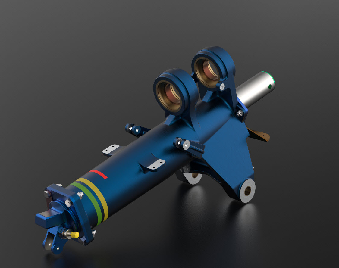
Having collated this information I started work on building the 3D Cad models, starting with the Tail Wheel Oleo Housing.
 This housing is perhaps the most difficult model in the series for the Tail Wheel and it has given me problems.
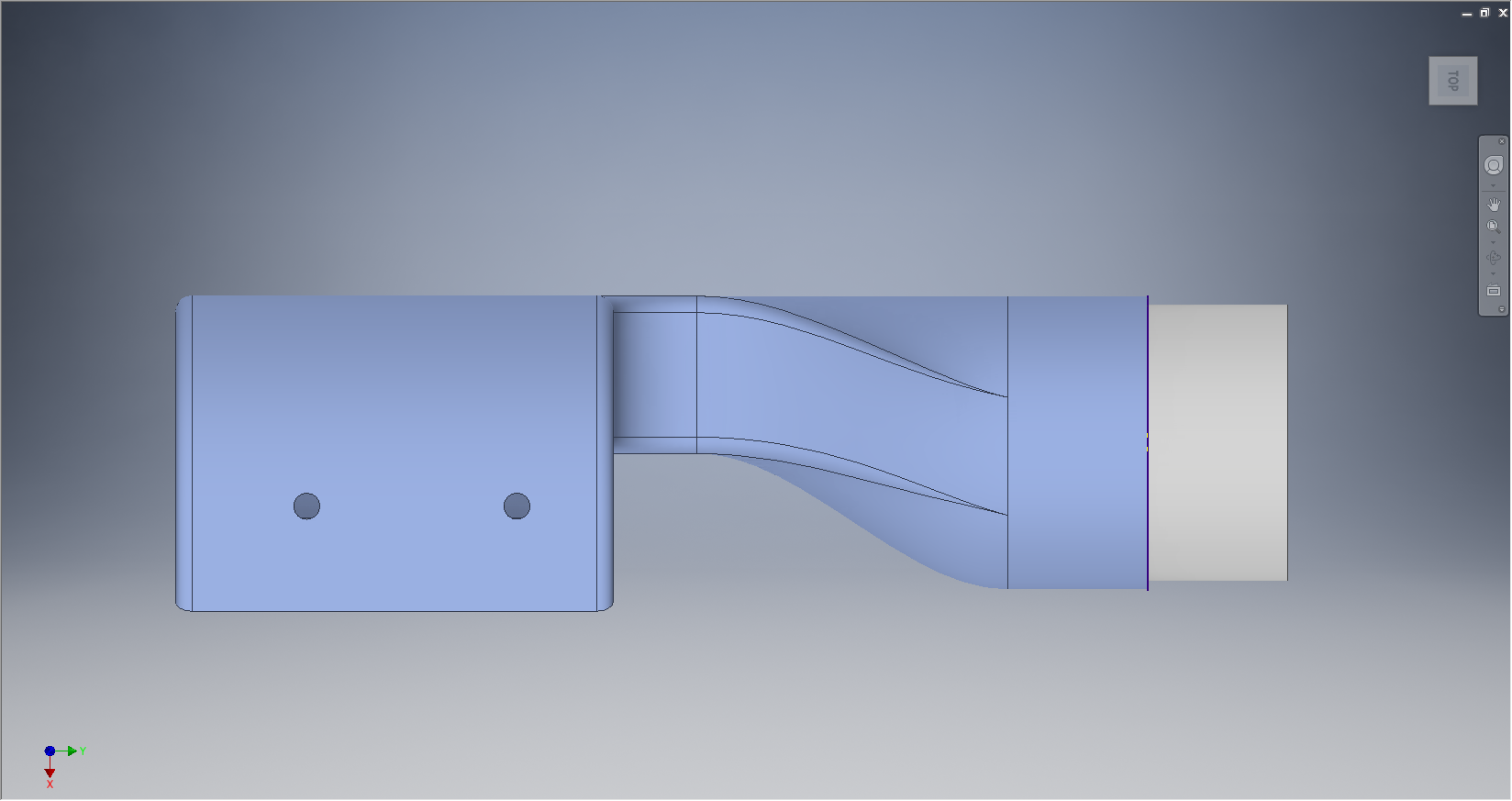
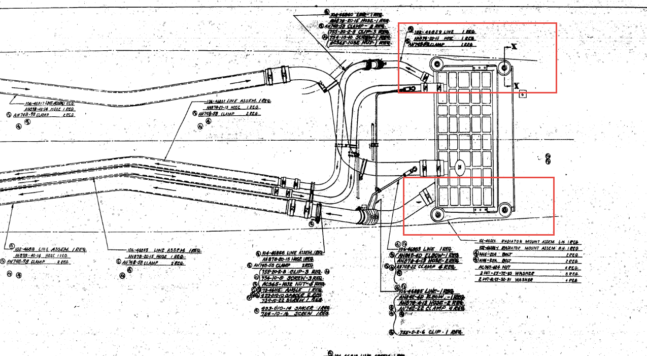
The main lower bracket struts are shown in the end view on this drawing as being tangent to the main body housing but the side view suggests that the alignment is lower than the centre and therefore not tangent. The main body is tapered from the middle of the main body so a tangent with the lower struts would be difficult to achieve…I know I tried it and the geometry was complex.
I wondered if this should be tangential as is typical of these types of castings. Sometimes its not too clear what the intent of the designer was and this drawing sure would have benefited from the inclusion of an additional section through the strut.
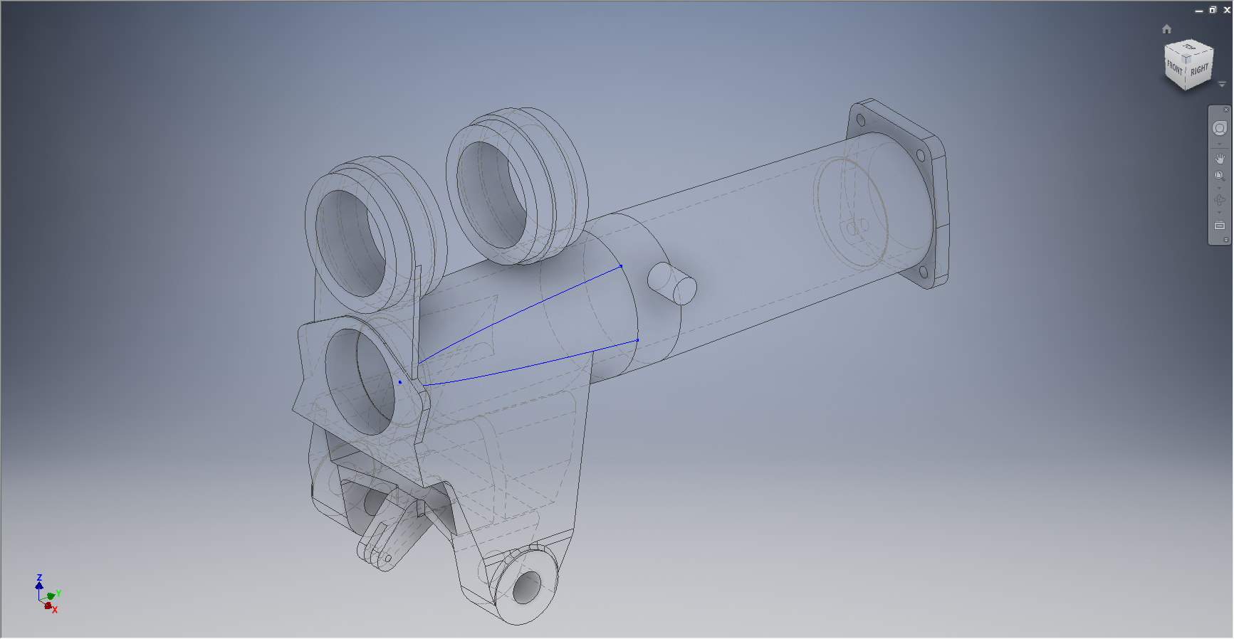
I couldn’t be sure what the intent was here and the plan view did not present any new information, however I did notice a small detail for one of the side brackets with a solitary single line that turned out to be a reference for the interface with the struts and confirmed that in fact this item is not tangent!
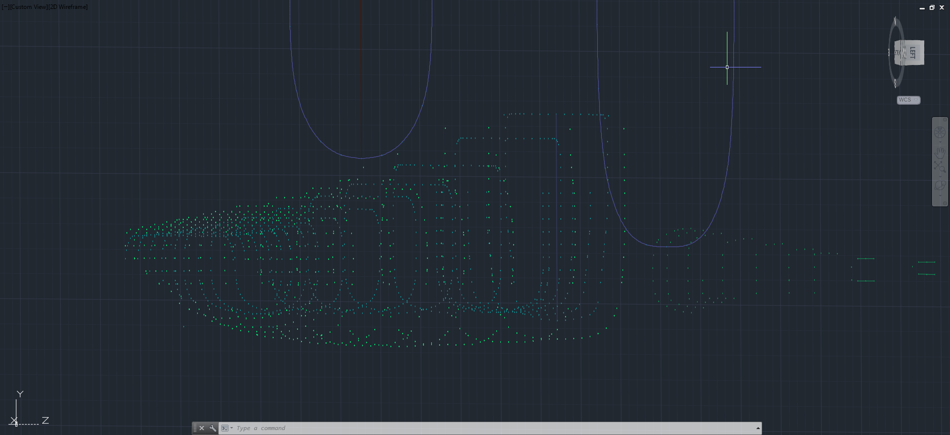
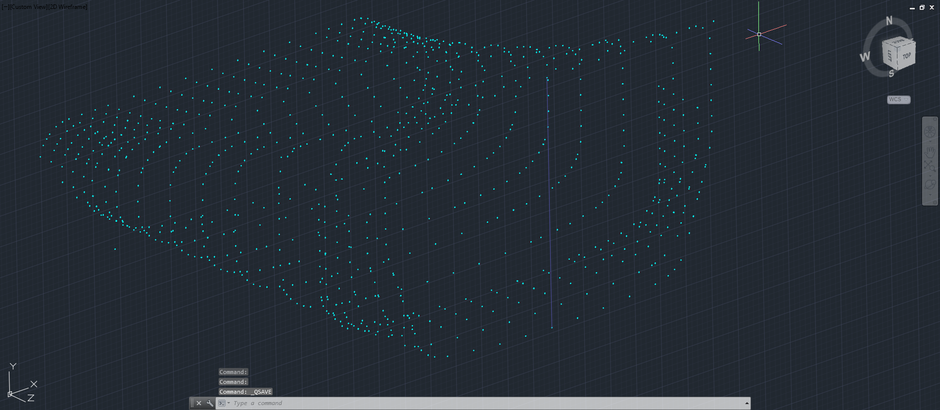
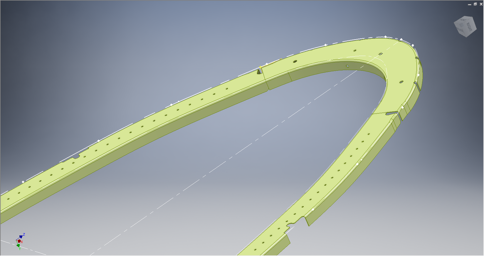
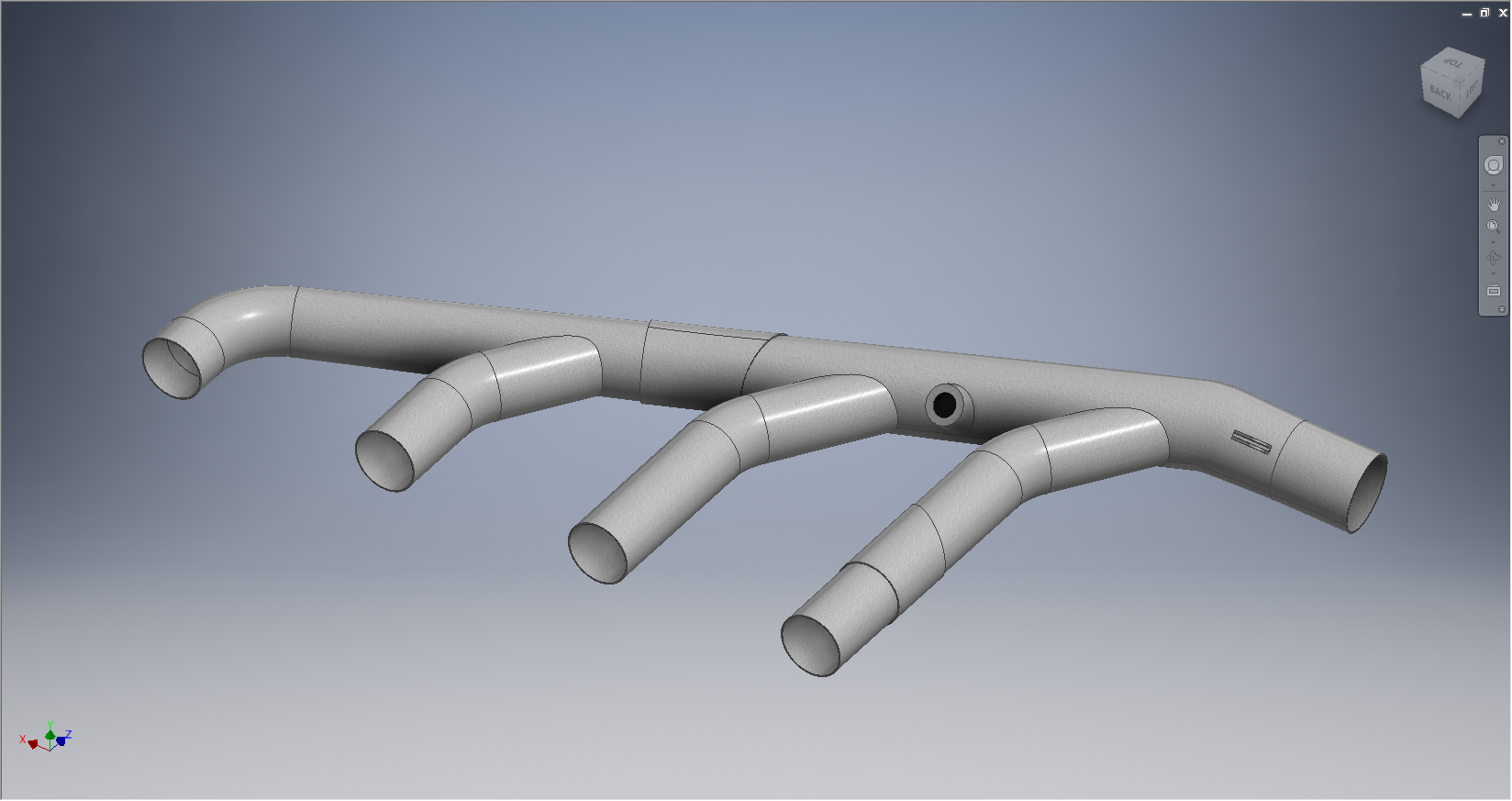
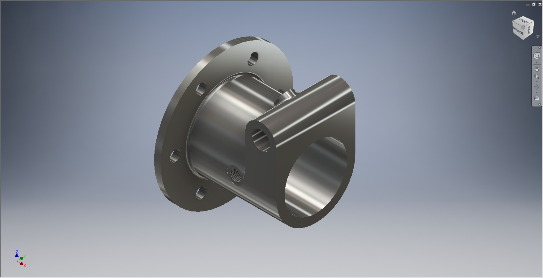
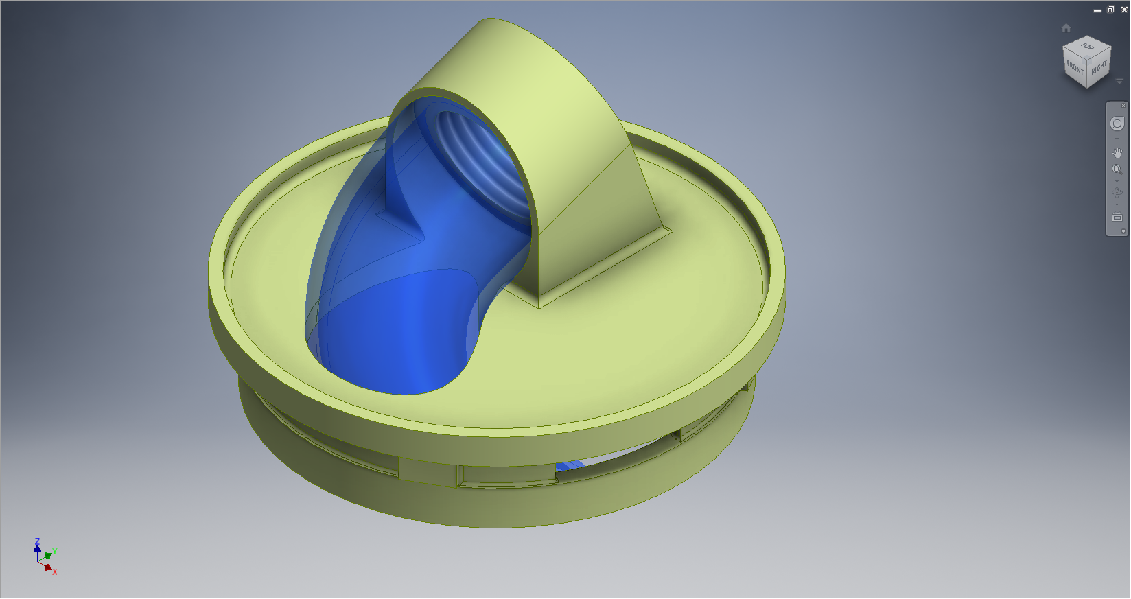
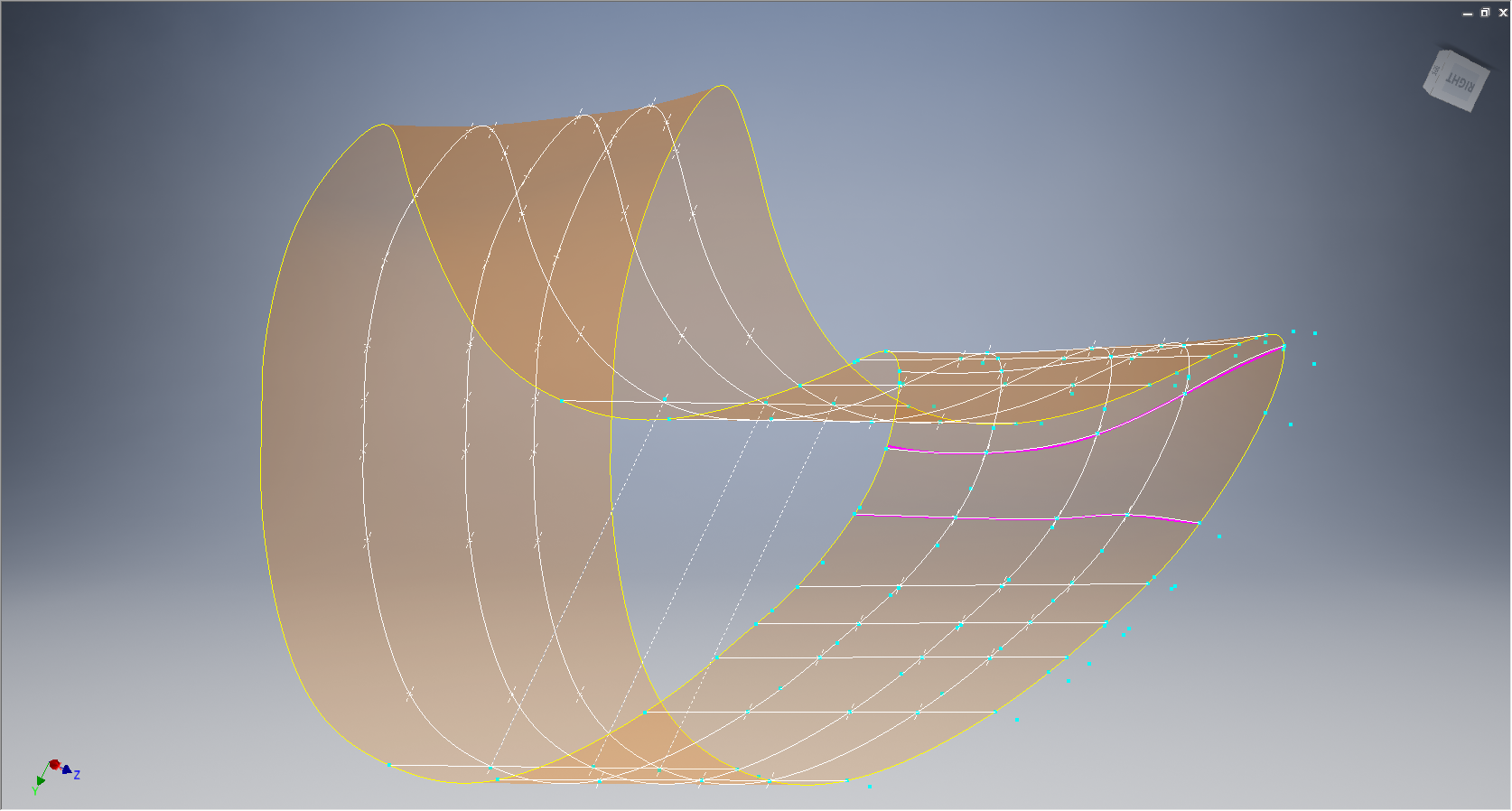
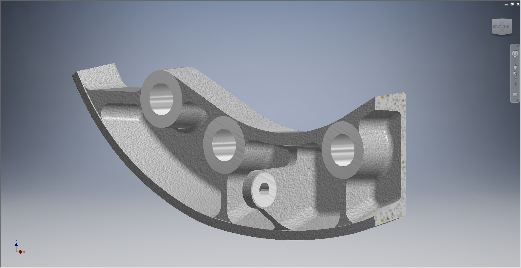
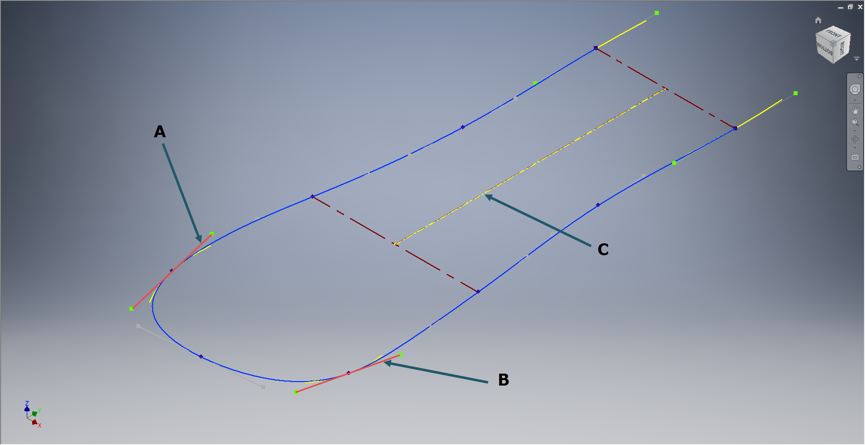
 This is the work-in-progress model which shows the generated profile of the junction between the main body and the lower struts, which satisfies the main details of the drawing.
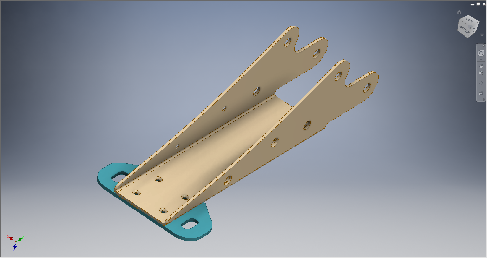
As it turns out the strut is tangent but only to the edge of the end of the main housing and not the main body itself. There is also a glimpse of a side mounting bracket which will be quite complex to model due to the nature of the curved profiles that will need to be developed individually and then lofted to define the final surfaces.
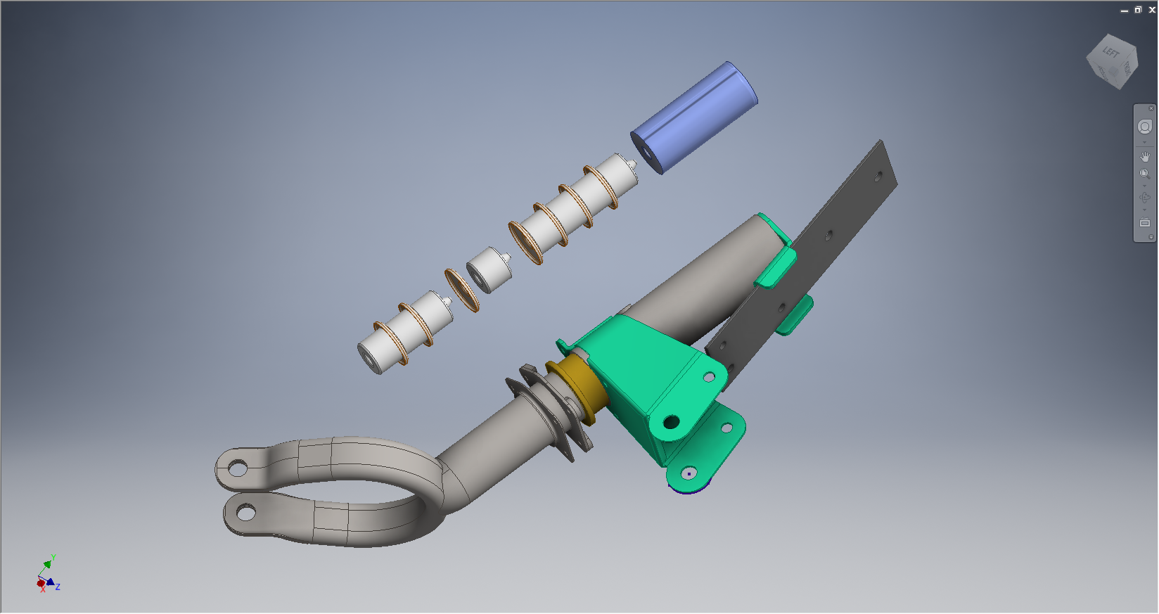
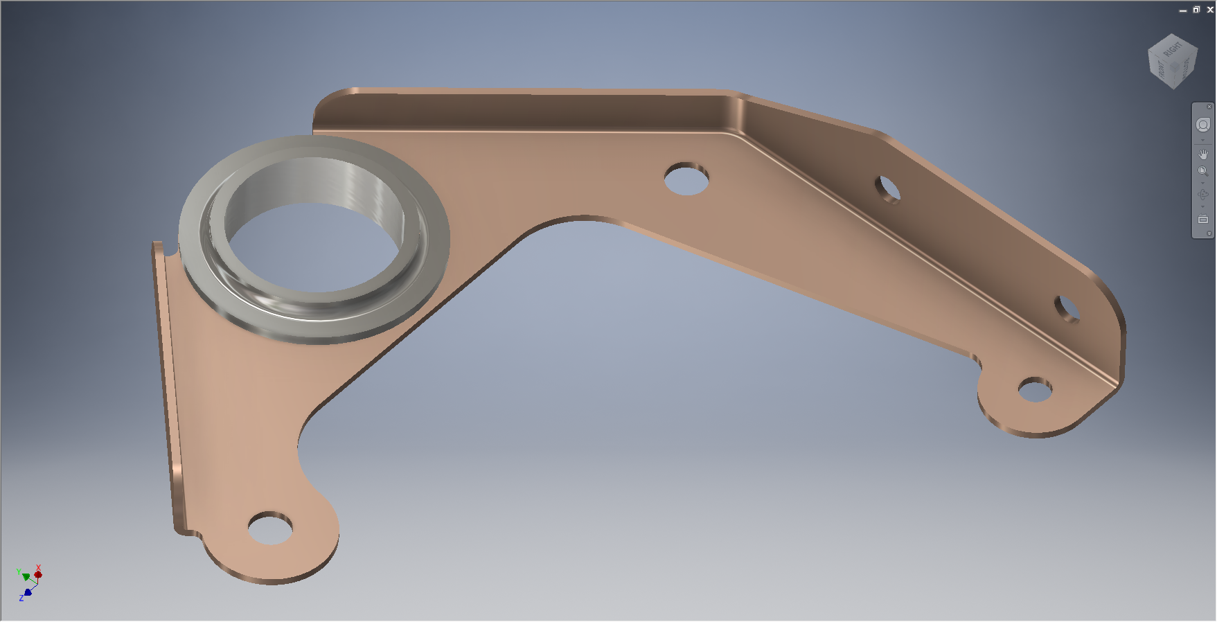
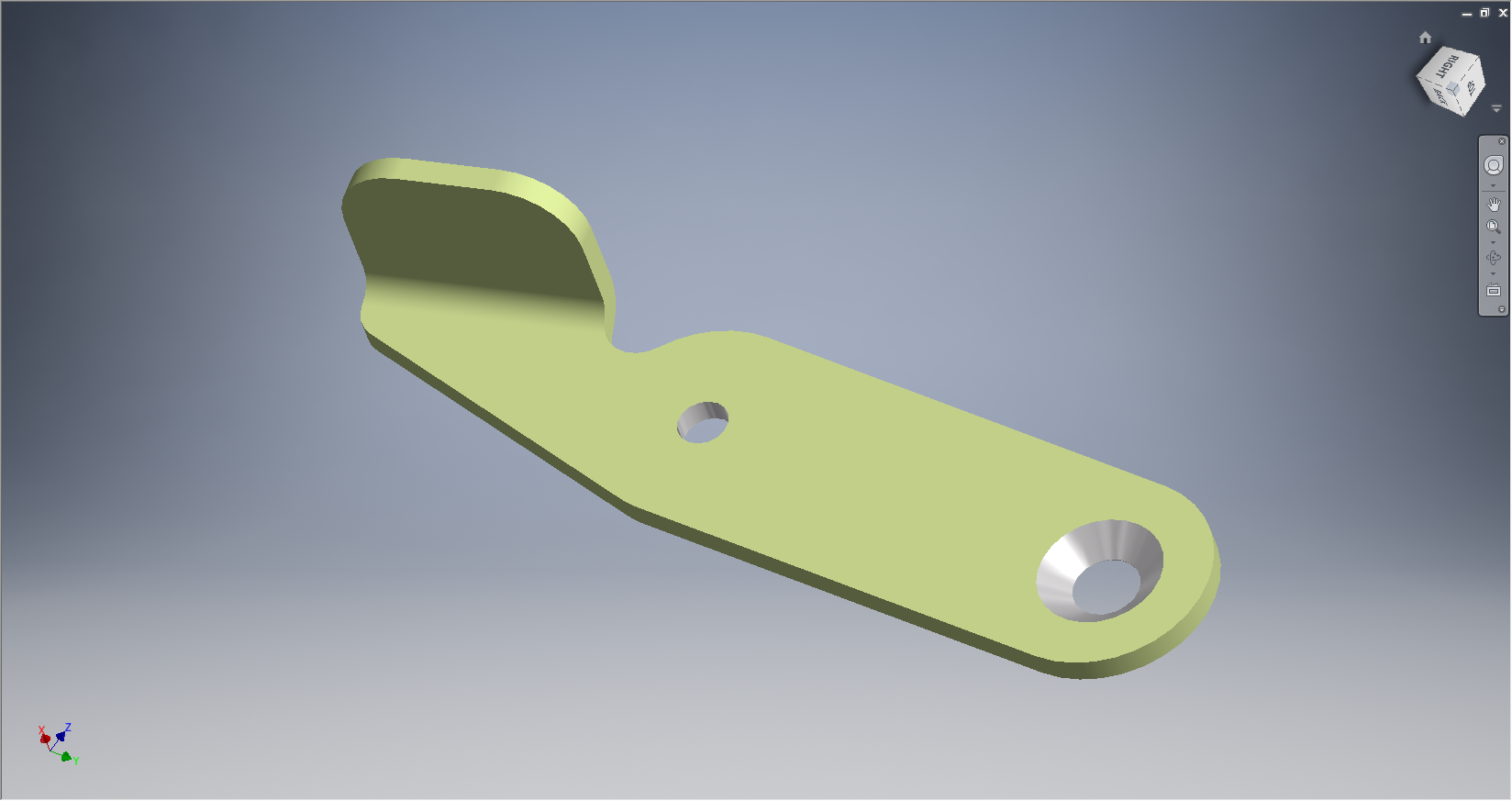
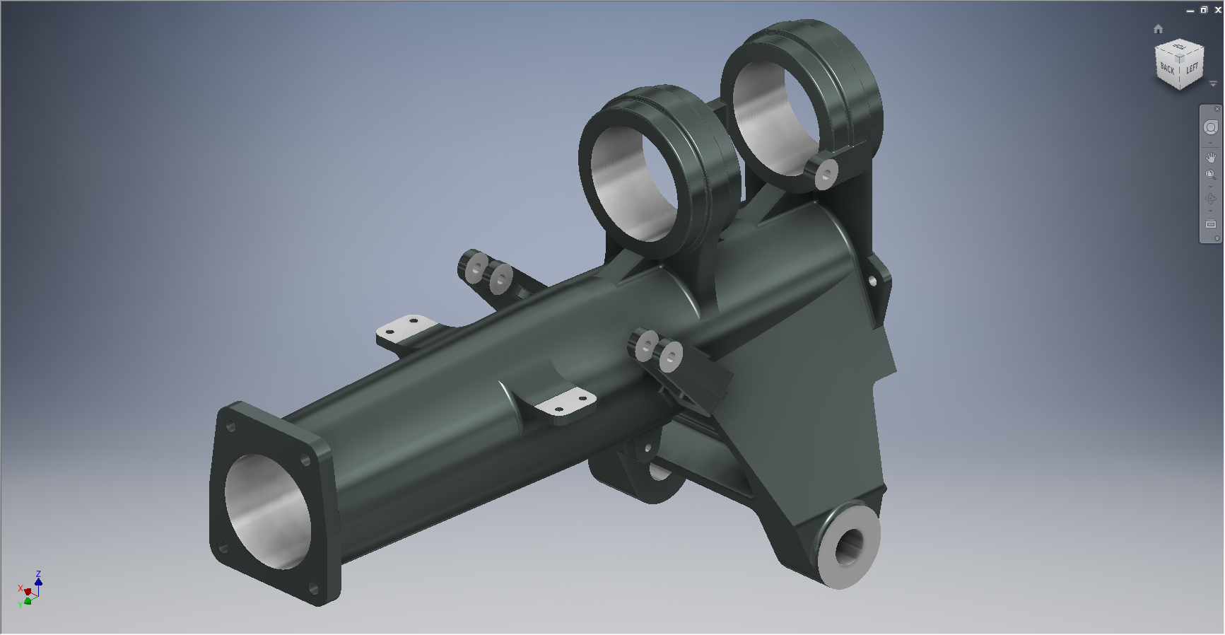
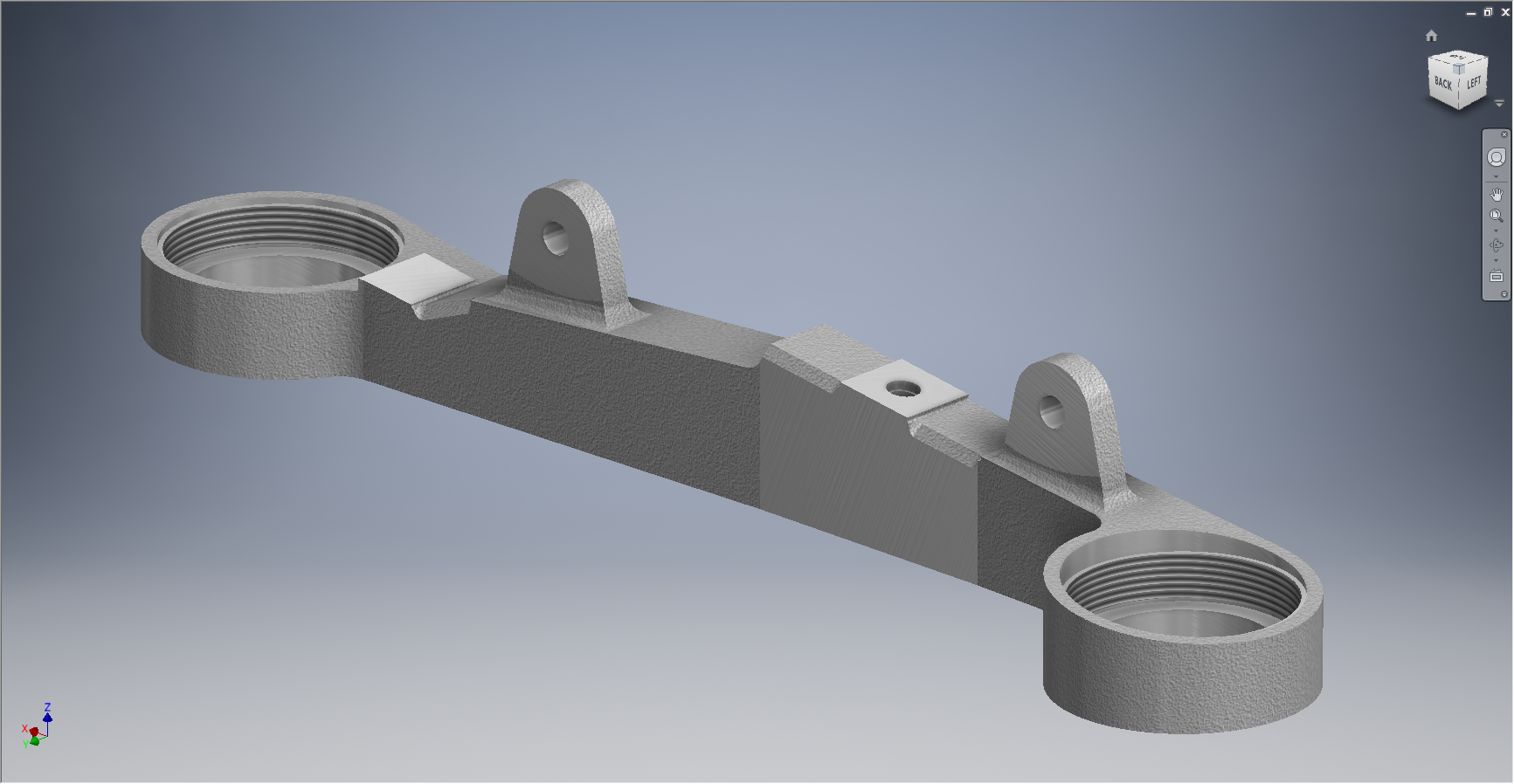
Update: Finished model for the Tail Wheel Housing item 91-34003. To complete this sub assembly I just need to add the bushings.

These models and several others are now available on CGtrader
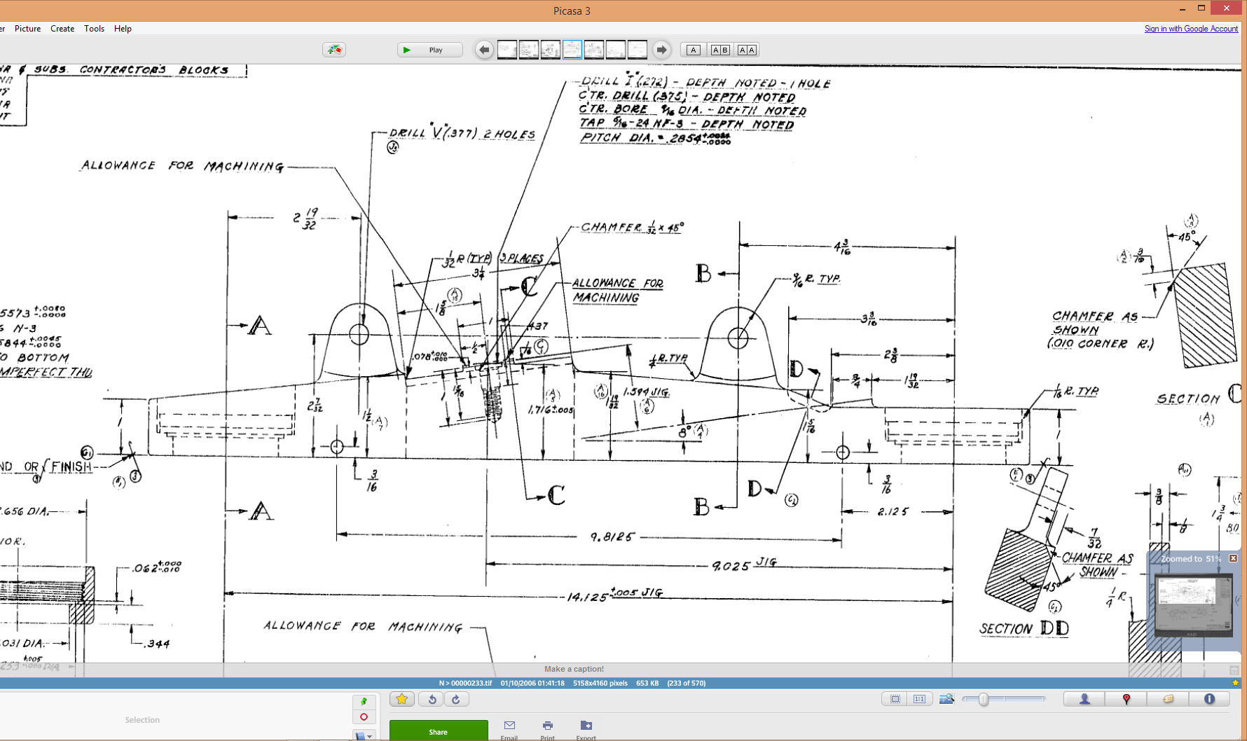


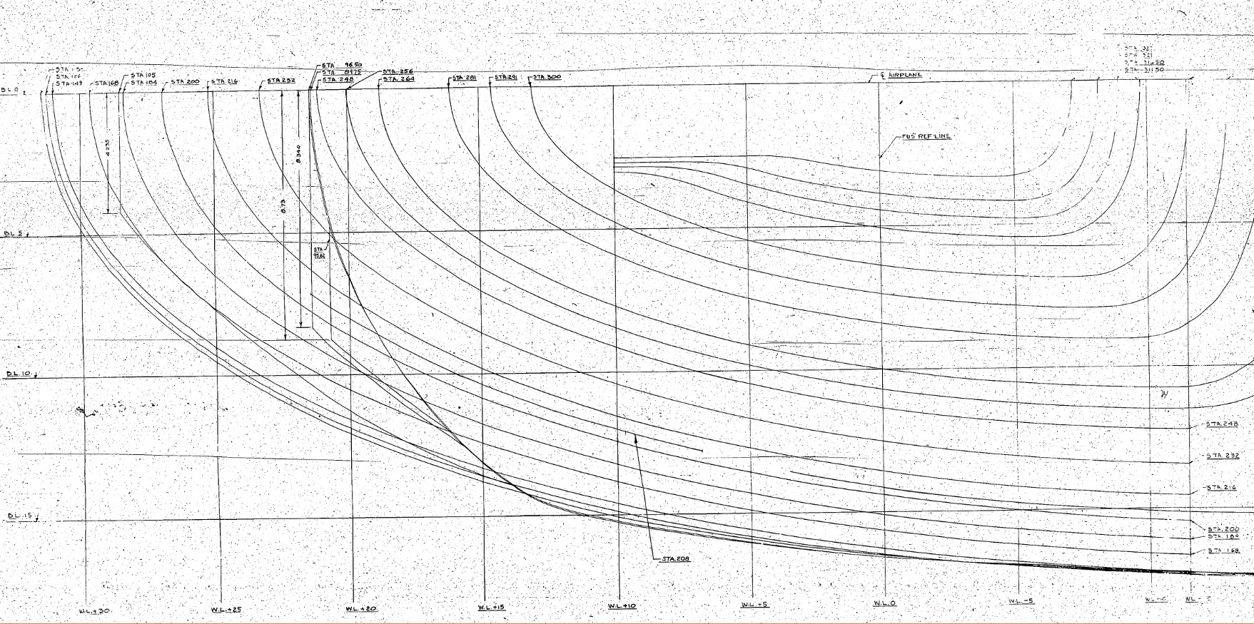

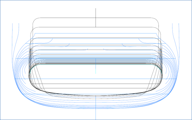
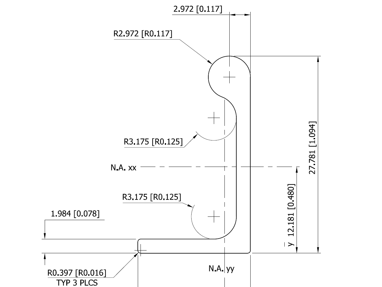
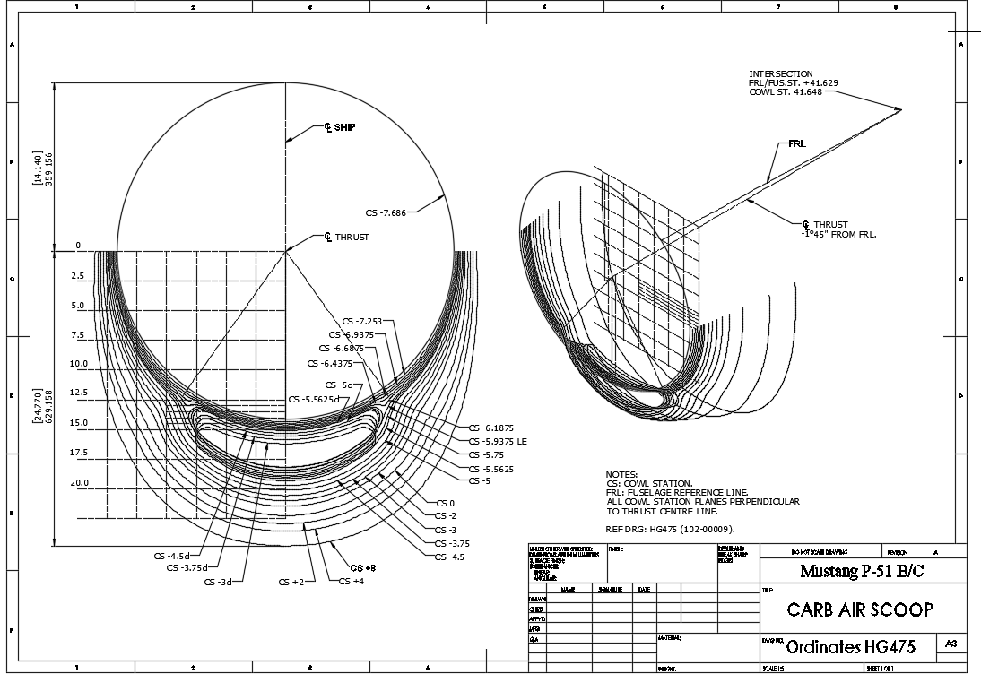
 This is a scrap view of the original NAA drawings showing the main ordinates for the Air Scoop.