NAA P-51D Mustang: Project Cad Technote; Smart Parts Vb
I was looking at options for routing the cables in the tailwheel assembly. There is potential for a lot of ancillary routing for pipes and cables yet to be done in this assembly so I have deliberately shied away from the adaptive parts (which I am not keen on) and the typical pipe and cable routing functions.
Also the cables are comprised of end terminals and many are sleeved for part of their length, which would mean having to route several times if I was to do this using the routing functions.
What I really wanted to do is have a sub assembly that contains the cable with all its bits in one sub assembly file but using the coordinates from the assembly to ensure correctness.
Extracting point coordinates from an Inventor assembly is not that straightforward requiring as in this case a vb solution, but first I had to define the key points.

I use the term “smart parts” and what this entails is for the parts or sub assemblies to contain additional geometry that will assist with other modelling activities like cable routing.
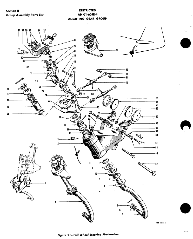
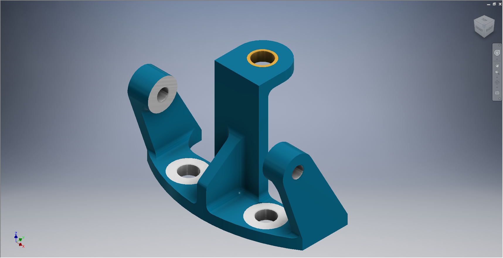
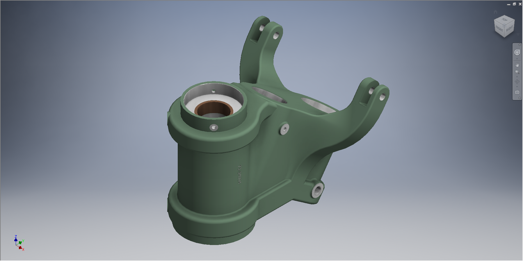
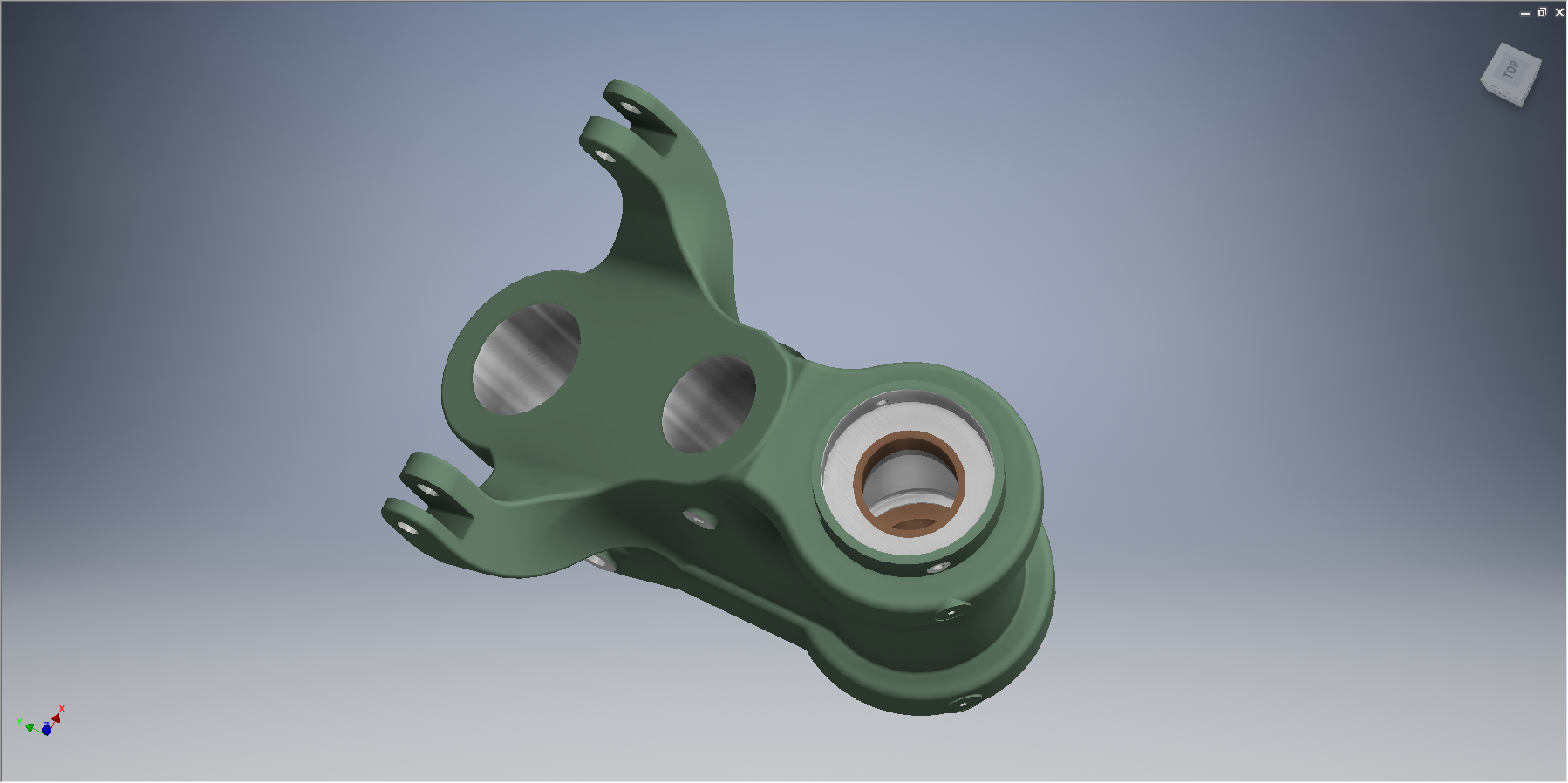
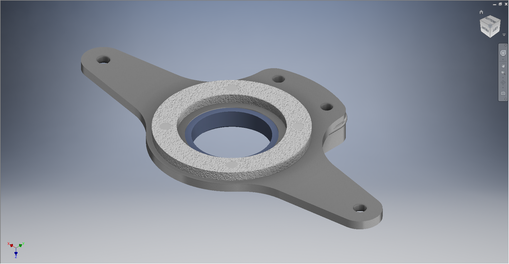
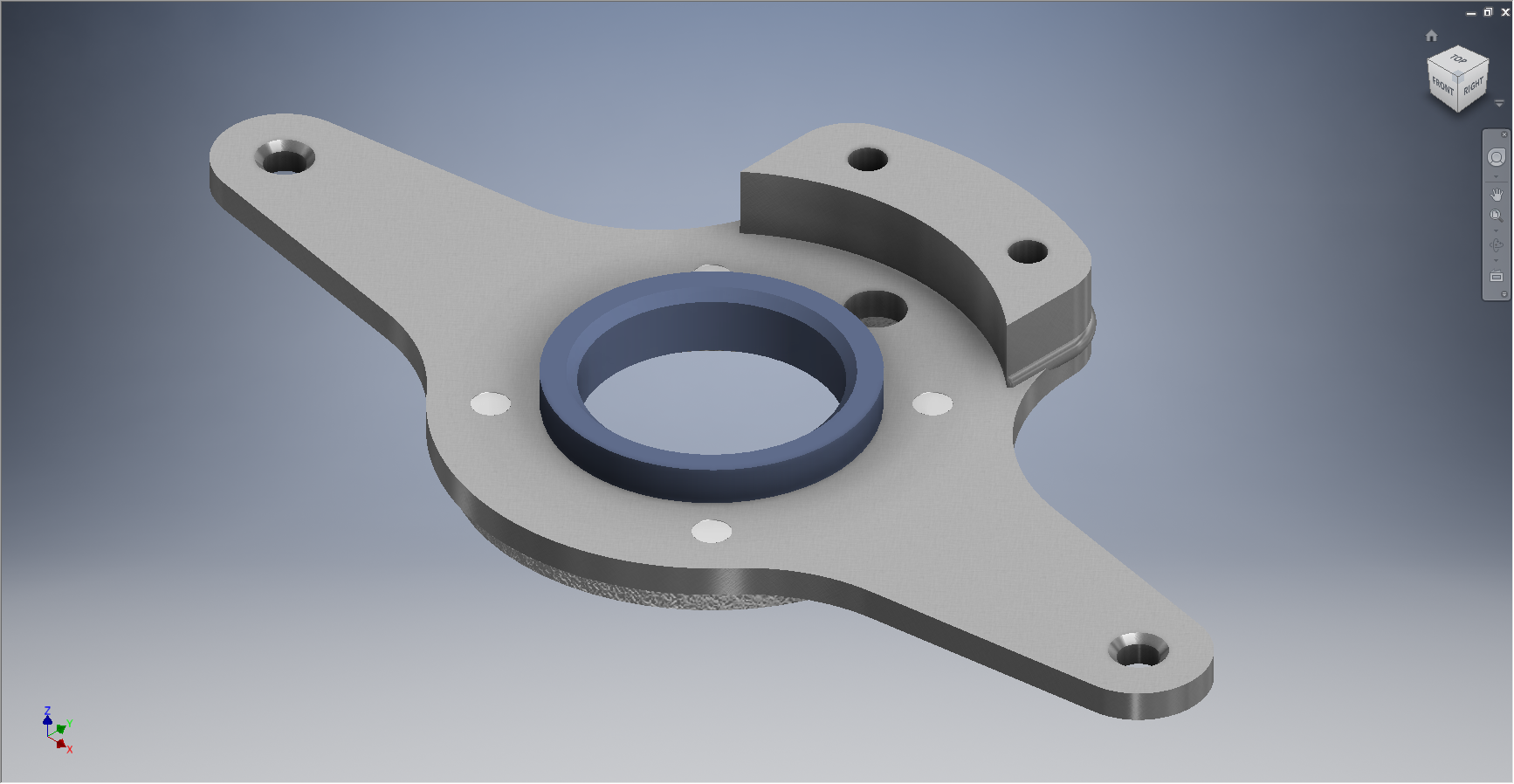
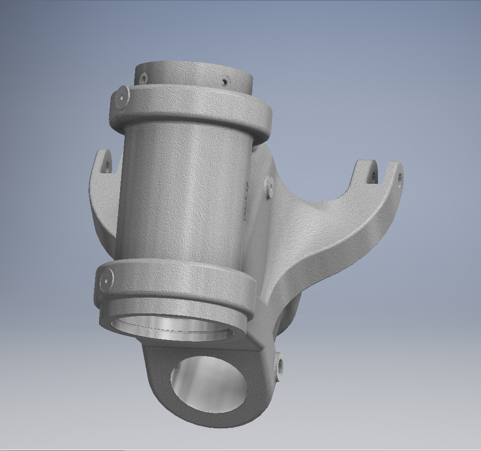
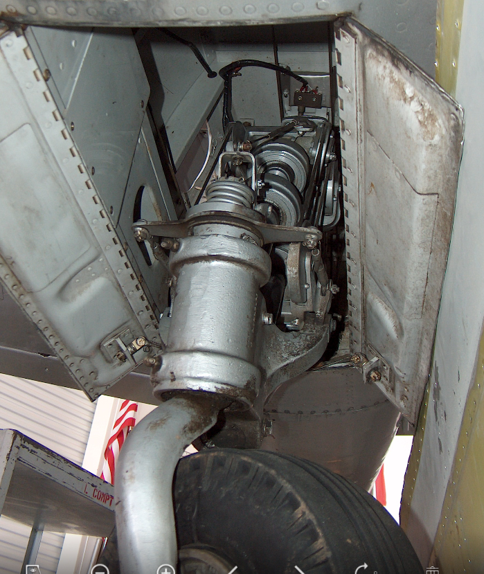
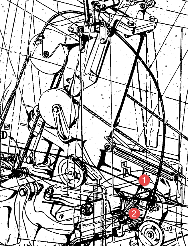
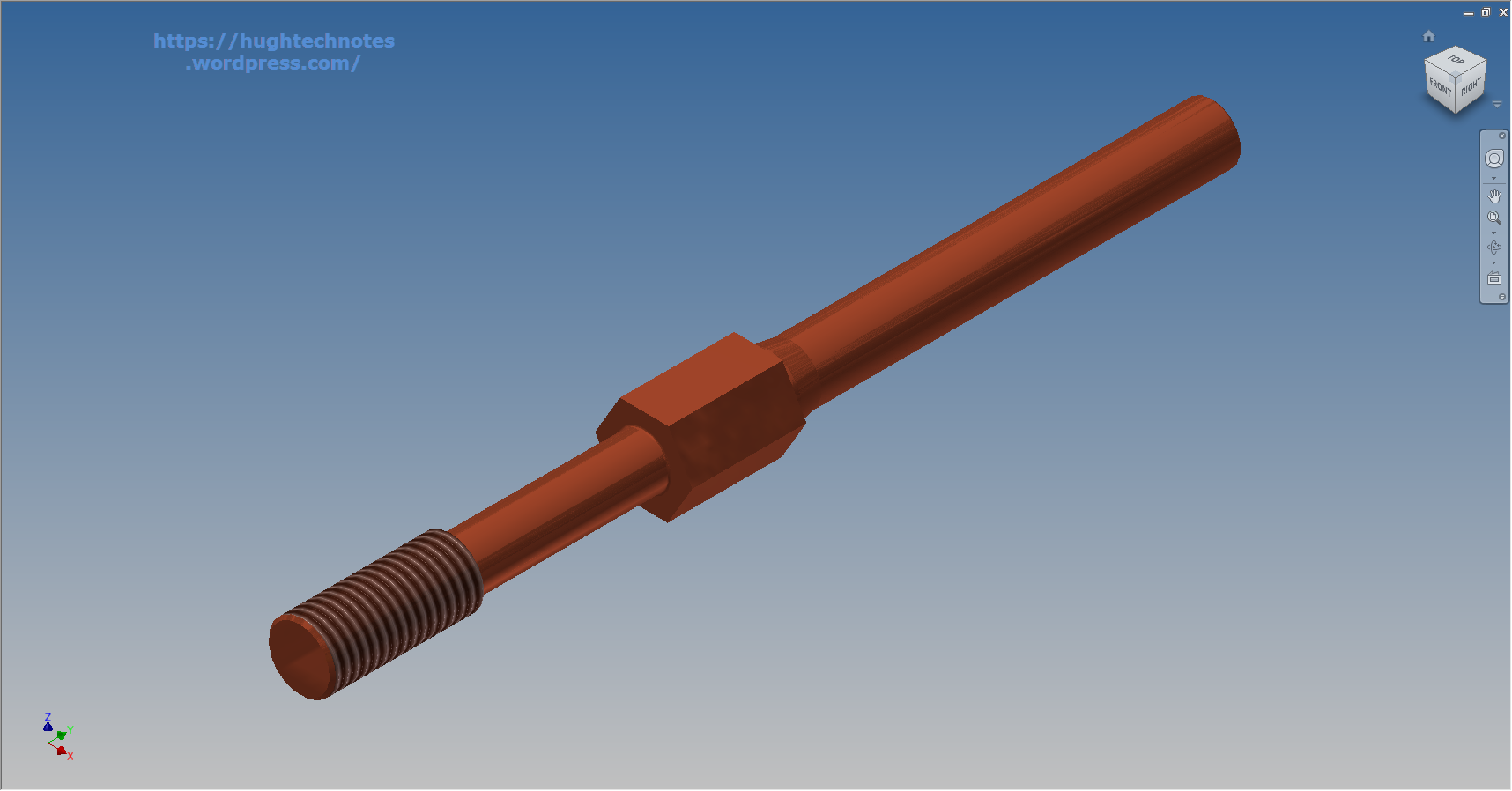
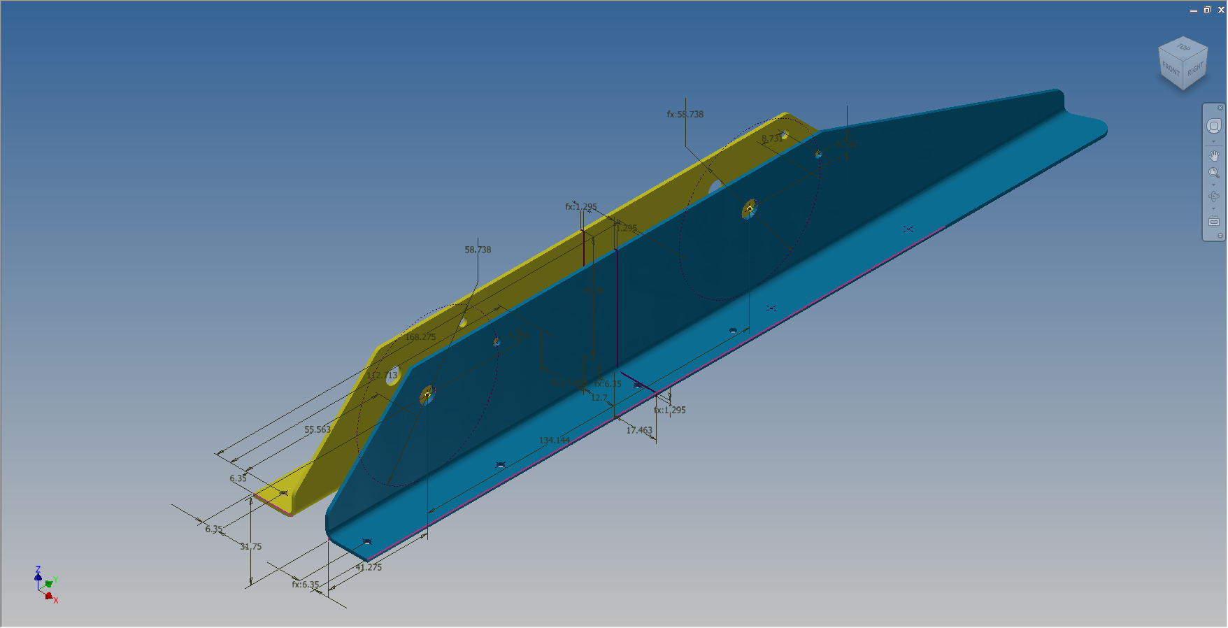
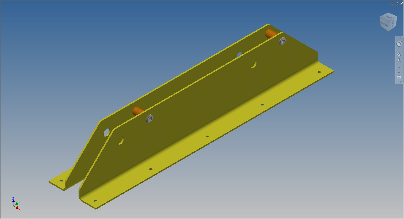
The image on the left shows the cables in this area with 2 key points 1&2 highlighted that are replicated in the 2 archive images. They define the straight section of the cable sleeve that is below and above the cable clips; the locations of which I have incorporated as points in the component sub assembly (last image). This sub assembly does not sit vertically in the assembly, the final position and orientation being determined by other factors which influences the final routing of the cable sleeve.
I have done something similar with the connection at the other end towards the left of the first image. At this stage I now have 4 points that determine the extent of the cable sleeve.
 The next step was to go to the main assembly and extract the X,Y,Z coordinates of the four points from the fitted components.
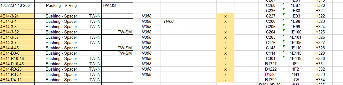
I first select these and run a visual basic routine to extract the coordinates of each point and create a csv file which I import into excel which in turn is imported into a separate Cad part file.
It was then simply a case of running a spline through all four points and sweeping the sleeve profile.
The great thing about this is that the coordinates are relative to the origin of the main assembly so when I import the cable sleeve into the assembly I only have to constrain to the origin planes and it fits perfectly.
 The cable itself will be done later in a similar manner which would be added to the sleeve part file as a multi part item or sub assembly using the sleeve centre line as part of the routing.
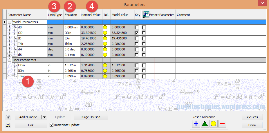
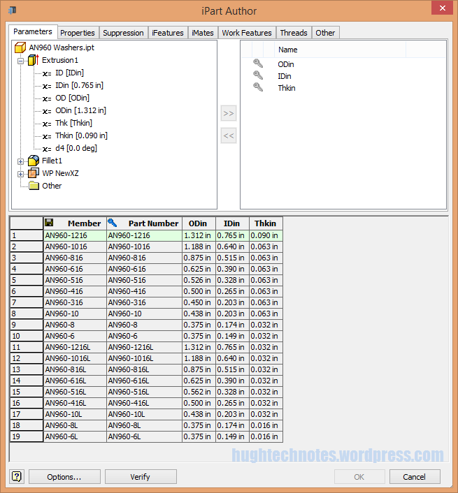
So no adaptivity, no complex pipe or cable routing just simple association through coordinate translations. The parameters of the sub assembly can be linked back to a spreadsheet so if the route changes I just re-extract the point coordinates and update the spreadsheet, which in turn will update the model.
To me this is a very tidy solution and maintains the integrity of the modelling hierarchy in accordance with the NAA register.
Using additional content in part files to facilitate other activities is very useful for examples like this and in fact any part that is associated with piping or cabling systems, particularly where you have cable clips or supports that need to be considered.
I should note that the extent of the cable sleeve is not exactly as shown in the first image due to the termination part not yet being modeled so I used something that was close at hand to demonstrate this principal.
If you would like a copy of the VB routine then please drop me an email and I will send it onto you.


 Occasionally though you do get the odd drawing that is almost impossible to use but having gained some experience in developing these aircraft structures it was not too difficult to determine the missing information.