Autocad Inventor: Splines

Spline Technote:

Splines are an absolute necessity when developing the finished profiles from the ordinate points; which occasionally throws up some unexpected results.  Invariably at some point we need to manage the curvature of the splines in order to achieve the desired result.
2015-06-09_10-15-47

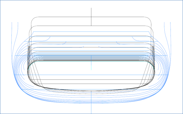
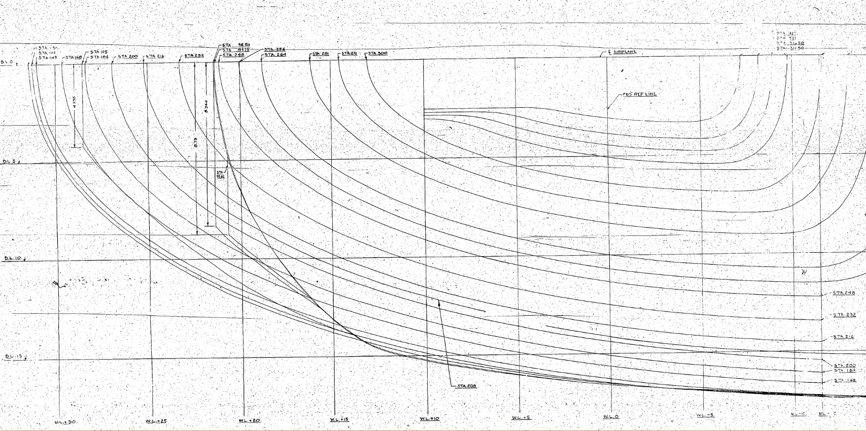
The image shown here is a screenshot from the NAA P-51 fuselage station profiles, which shows clearly the ideal curvature for each station.

This image can be overlayed in CAD to serve as an aid to achieve the correct spline curvature.

Actually manipulating the curvature of a spline needs to be done in a manner that achieves symmetrical results on both sides of the fuselage station profile.

I was working on the tail-end profiles, which were giving me grief as the ordinates points were not sufficient to achieve anything close to the curvature I needed on the lower section.
2015-06-09_13-26-35

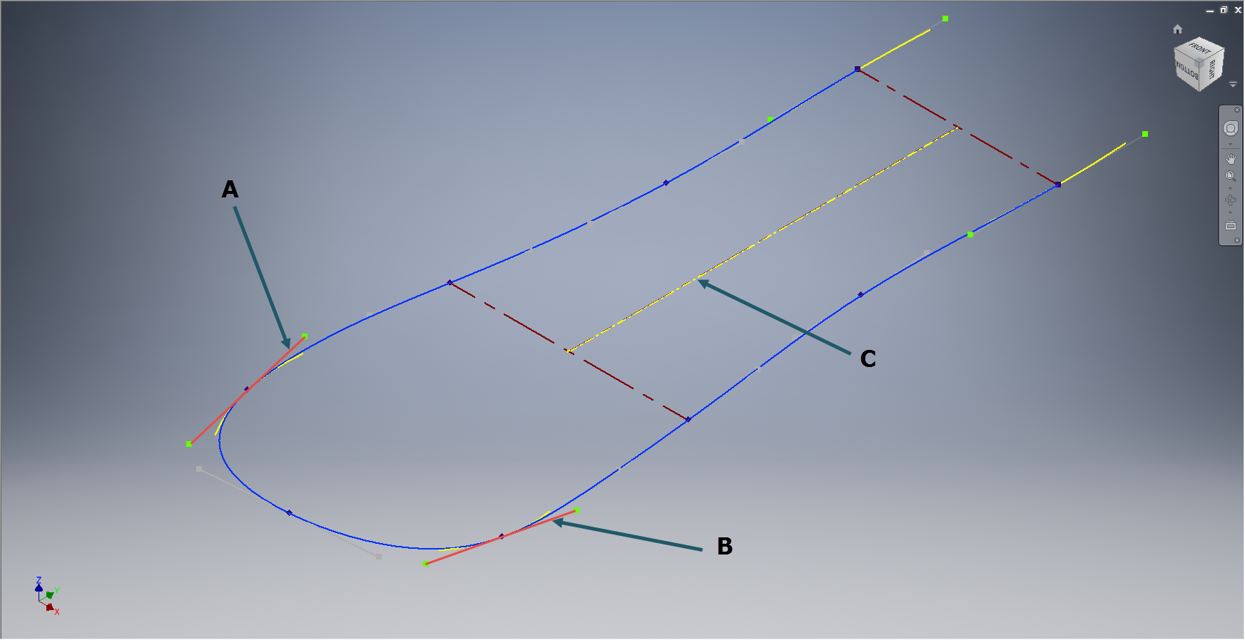
In Inventor we have constraints for symmetry, which are normally applied when working on a sketch to ensure that changes on one side of a model are reflected exactly in the other.

Using this same technique I activated the spline curvature handles (A&B) on each of the  points I wanted to be symmetrical (about center at C) and applied the constraint accordingly to the handles (red).

2015-06-09_17-29-44Now when I adjust one side of the curve the other side automatically reflects the changes.

I should note that the majority of curves generated from the ordinate points are usually very good; requiring very small if any adjustments; so its quite practical to spend some time in the areas where they are not so good.

At some stage the profiles will be lofted as a surface which would then be analysed to verify curvature and alignments.

North American P-51 Mustang: Wings

NAA P-51D Mustang: Wing Geometry

Started work today on the wing geometry and ordinates.

This is the last ordinate data-set drawing I have in my P-51 archive and probably the most challenging, thus perhaps the reason why I left it until last!

2015-06-06_22-51-32The quality of the scanned drawing is not that great with much of the data missing or obscured and requiring a fair amount of interpolation to derive the correct values.

The interpolated data is derived through the use of various techniques within Excel, including polynomial curve formulas to determine the values I need from the known data.

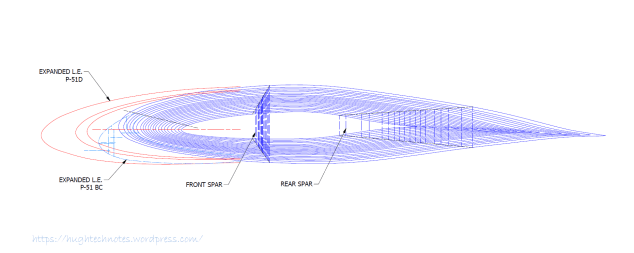
So far this has worked out rather well enabling me to make a start on a geometry plan for the wing which will verify the relative dimensions of the Leading Edge, Front Spar and the 25% Chord line.

This drawing is still “work in progress”, which is shown for reference.

The wing ordinates are cross-referenced against 3 different sources to ensure correctness.

Update June 2018:

I have revisited this spreadsheet to include generated excel profiles to check the ordinates and also to derive the XYZ coordinates for input into CAD, centered about the front spar position. The missing and unknown values are now sorted thanks to a new resource…the spreadsheet is complete and verified. See Mustang Ordinates for full details.

P-51D WING ORDINATE

P-51 Wing Profiles

North American P-51 Mustang: Air Scoop

North American P-51 Mustang: Air Scoop

Working with ordinates from these archive drawings can be a very time intensive operation. To give some idea of the content of this work I have just started working through the vast amounts of ordinate data for the Air Scoop and Oil Cooler.

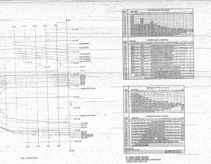
2015-06-04_12-23-12 This is a scrap view of the original NAA drawings showing the main ordinates for the Air Scoop.
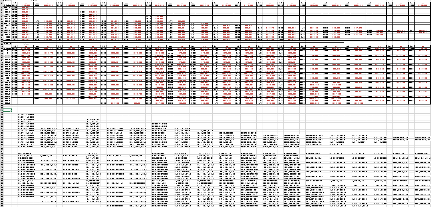
This drawing shows 2 tables, one of which is the listing for the external contours and the other the internal contours.

The external ordinates comprises a total of 664 points and the internal ordinates comprise a total of 928 ordinate points.

Each point is manually entered into a spreadsheet which lists the Inch dimensions and then converted to Millimeter dimensions.  The data has 3 values for the Station location, the Waterline (value along a horizontal axis relative to the ship ctr line at set intervals) and the Buttock line (value along a vertical axis relative to Frame Ref Line ).

2015-06-04_10-19-41       2015-06-04_10-17-50

These values are then processed using the concatenate function in Excel to extrapolate the required X,Y,Z coordinates.

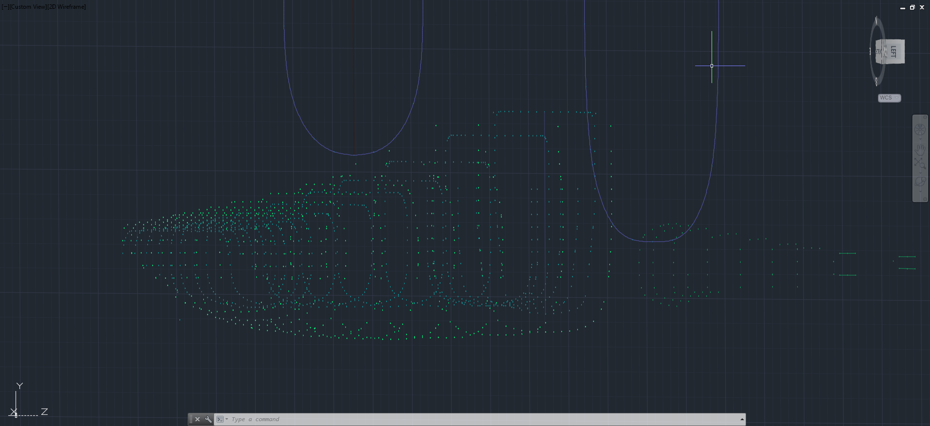
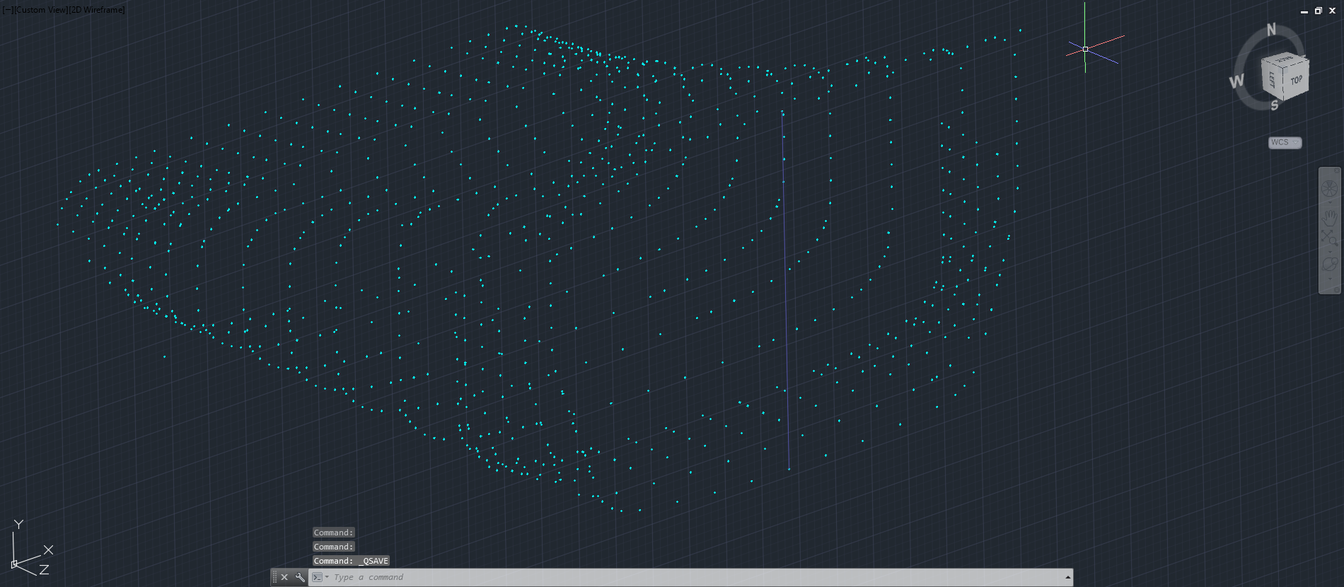
The points are then grouped and imported into Autocad to derive a point cloud.

2015-06-04_16-57-59 2015-06-04_11-04-09

The first screenshot is all points combined with the local fuselage contours shown for reference; the second screenshot is the internal point cloud. All these points would then be contoured in Autocad to determine suspect locations and any orphaned points.

The external point cloud had 6 points prominently out of sync with everything else which turned out to be an error in the original data set. This is not uncommon and is usually quickly resolved.

Once I have an initial dataset that satisfies these primary requirements I would then import this data into Inventor or Solidworks for evaluation as a surface in each case.

At this stage, I have spent about 3 days on the data preparation and would expect to spend at least a week to properly evaluate the surface definitions.

It can be very satisfying work when you see for the first time all these data points translated into something tangible as a 3D model depicting the end product first realized all those decades ago.

Update: Decided to pull out all the stops and complete the datasets and point clouds:       

North American P-51 Mustang: Fuselage

North American P-51 Mustang: Fuselage

The drawing archive I have contains quite a large selection of legible fuselage frame drawings which I am collating according to the Station reference on the fuselage. I have a spreadsheet that lists all the Mustang drawings including the original drawing number, the scan image number and location within the archive.

Each fuselage frame at each of the designated stations may comprise 3 or more elements, which unfortunately are scattered throughout the many rolls of scans thus requiring some exhaustive work with the spreadsheet data-sets to sort the numbers and folder locations in order to identify and collate the required frames for each assembly per aircraft type.

One such frame was at station 216 which I decided to model; partly due to the fact I was getting fed up looking at and sorting spreadsheet data.

2015-06-02_13-11-07 2015-06-02_00-03-52

There are several methods to modelling this and whilst I was subject to the vagaries and still limitations of the Inventor product (Solidworks has more options for working with splines) I developed a workflow that obviates some of these limitations and also how the end product is finished.

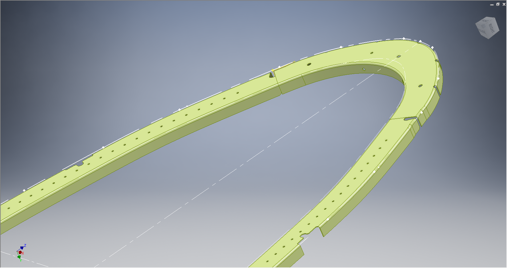
One way of doing this is to simply create a surface for the main plane and then project a flange line along the edge to create a”folded” surface and then apply thickness but this method gave some unusual iterations in the smoothness of the fillets at the end of the profile. I found that the best way is to create surfaces for all six faces; the splines inside and outside, the top and bottom planes and the ends, then sculpt to create a solid.

I would then go out about creating the notches and cutouts in the solid and then shell the solid to the required thickness. This works very well and ensures the integrity of the original spline ordinate lines (which would have to be split to do this any other way). This method also maintains better continuity of the end fillets and curvature (image 2).

The frame drawings reference the mold line ordinates, which I have for the P-51 B/C Mustang variants.The P-51D is similar with the exception of the ridgeback on the main rear fuselage that has been reduced above the +10″ W.L.

Techy stuff: I mentioned a limitation in the Inventor software which relates to creating a line perpendicular to a spline. In Solidworks you just sketch the line and constrain it perpendicular to the spline, but you cant just do it this way in Inventor (as far as I know). What I did was use sketch construction lines to define the point of intersection with the spline that I wanted the perpendicular line to start from. As I already had a surface projected from the mold frame spline (for above construction) all I had to do was create a new plane perpendicular to this surface at the selected point. It was then quite simple to create a further sketch to define the line I wanted perpendicular to the spline at the correct location.

De Havilland DH82c Tiger Moth

 De Havilland DH82c Tiger Moth:

This is a selection of parts developed in 3D CAD for the Tiger Moth DH82c (Canadian variant). I had hoped that the original drawings and corresponding data sets would be sufficient to actually develop the entire aircraft, unfortunately I was stumped by the fuselage dimensions which remains incomplete. A few key dimensions were illegible on the drawing copies I had and although I tried to source legible information from various places I was unsuccessful.

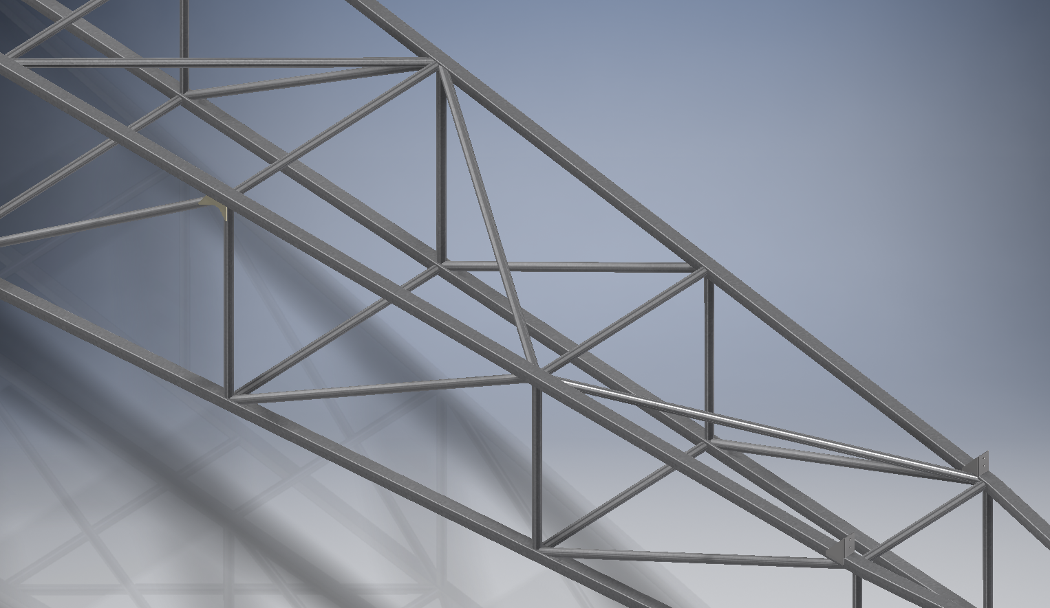
Tiger Moth FuselageI have though interpolated a solution for the rear fuselage based on available information that seems to satisfy the requirements for manufacture and assembly.

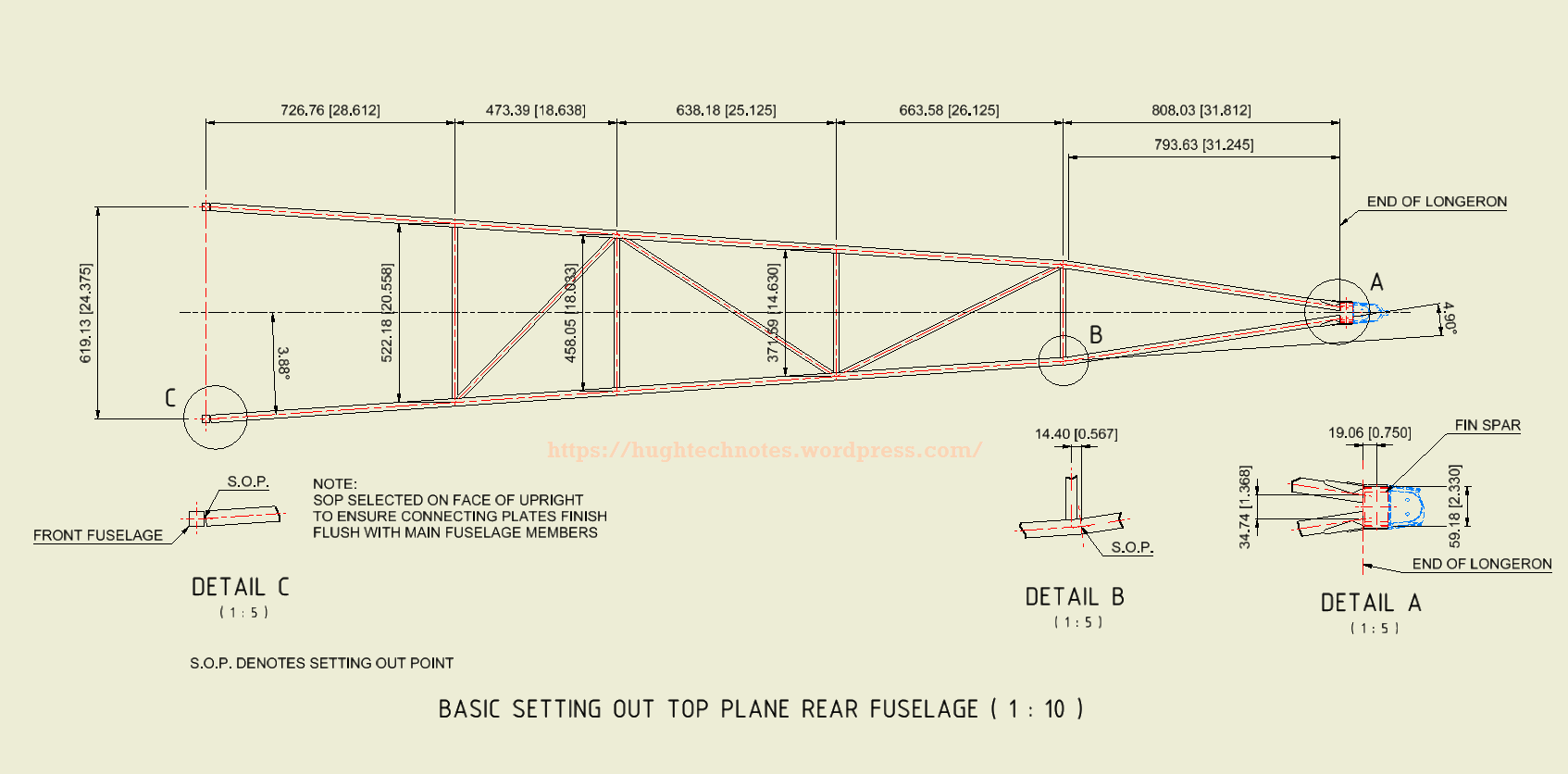
DH Moth fuselage WIPThe archive drawings suggest that the setting out point between the front fuselage and rear fuselage members is coincident on the centre line. However this would not facilitate a flush connection with the bent plate connector, so I have offset the SOP to the face of the front fuselage upright, which does. Notice too the minor adjustment to the angles.

These setting out dimensions are not verified and the drawing should not be used for any other purpose than for reference. I don’t normally publish stuff without verifying the data but this fuselage has bothered me for a while so I thought it may be prudent to publish what I have in the hope that someone may provide the verifiable data I would need. The model shown is work in progress.

This has proved to be an interesting project and I progressed quite well with the tail and various other elements of the design. I hope to return to this project at some later date as it is a fine aircraft with many examples still flying.

2015-07-31_13-30-562015-07-31_13-27-37

2015-05-31_23-16-23 2015-05-31_23-15-59 2015-05-31_23-15-37 2015-05-31_23-15-04 2015-05-31_23-14-48 2015-05-31_23-14-27

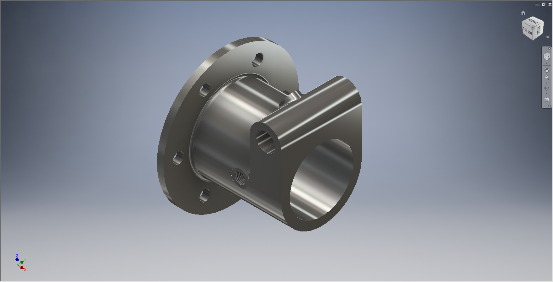
H22414-0313 H22143-0309 Tiger Moth Axle Collar 2015-08-30_03-47-08

2015-08-30_04-08-18 2015-08-30_04-13-20

2015-09-18_03-45-42 2015-09-18_03-45-12

North American P-51 Mustang: NAA Profiles

NAA P-51 B/C/D Mustang:

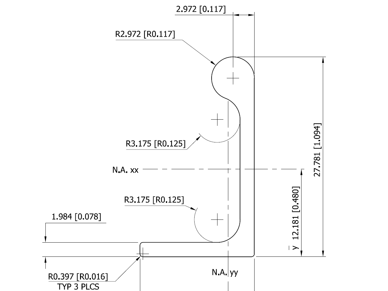
The majority of parts created for aircraft like the P-51 are derived from a library of standard section profiles, not unlike the steel and ship building industries. Fortunately for this project we have an extensive collection of these original NAA standard drawings, numbering 208 in total.

To facilitate the long term goal of recreating the P-51 part drawings as 3D models and associated 2D drawings I figured it may be prudent to first recreate the standard profiles as 2D CAD profiles for this purpose.

So far I have drawn the first 24 profiles exactly as shown on the original drawings but with dimensions in dual format inch & mm…many more to go!

NAA-1E1          NAA-1E1a

North American P-51 Mustang Parts

NAA P-51 B/C/D Mustang:

Ordinates interpretation, translation and development are an important part of my research work and rather essential to the development of the many part and frame components.

It would be great to be able to develop a full parts library for any of these aircraft projects in 3D CAD and recreate the original drawings. However the number of parts in any one aircraft is prohibitive to achieving this goal. I do though occasionally indulge in developing some of the part drawings; in 3D and 2D; if nothing more than a challenge to recreate something that was first designed 75 years ago!

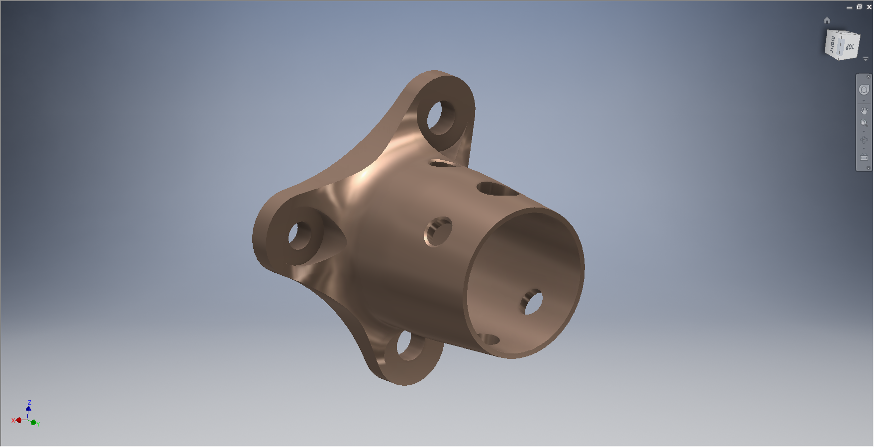
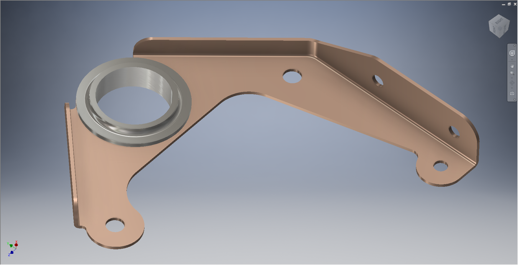
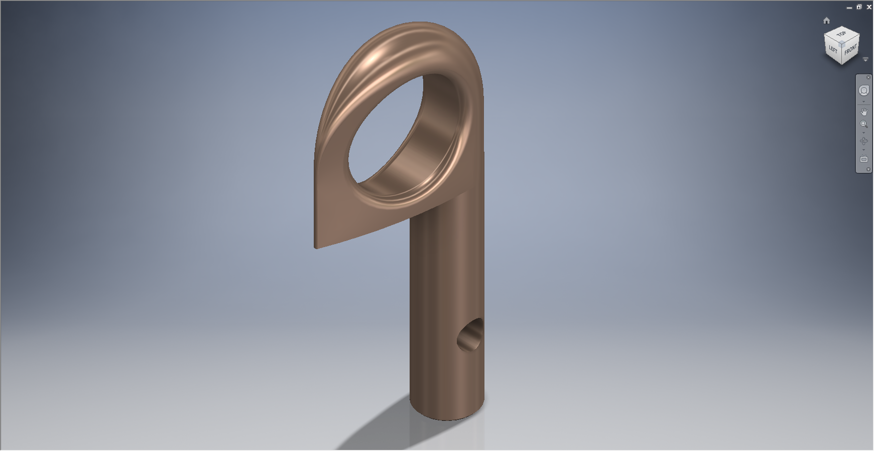
These are some of the parts modelled for the P-51 Mustang:

2015-05-31_00-14-57 2015-05-31_00-14-13

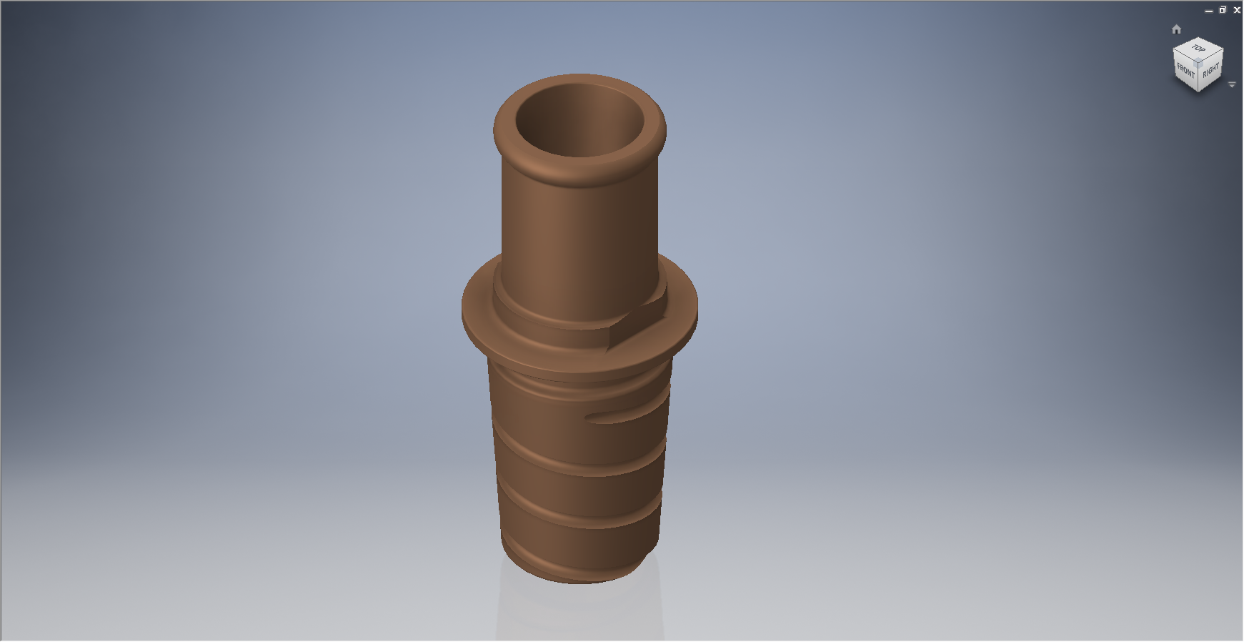
73-47058 Flange: Oil Tank Filler Neck               73-52144 Fitting: Aileron Control Stick

2015-05-31_00-20-39 2015-05-31_00-20-25

99-33463 Clip at Wing Station 56.625           99-318116 Link: Cockpit Encl Exit Hatch

2015-05-31_00-20-54 2015-05-31_00-14-31

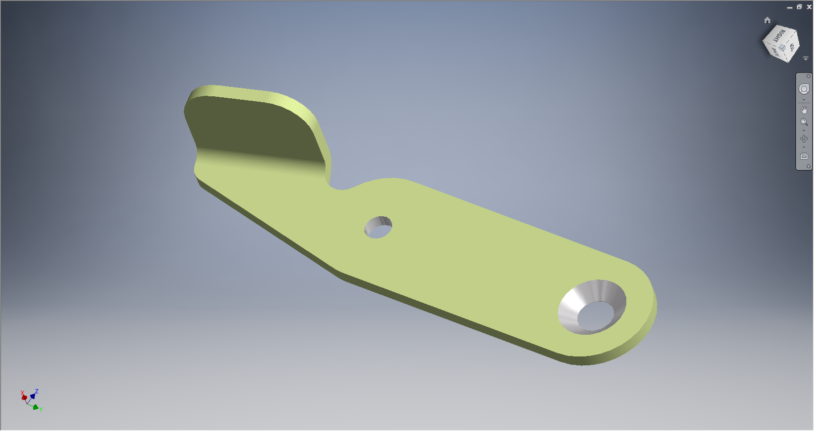
99-318134 Bracket: Cockpit Enclosure               106-48343 Bracket: Fuel Valve Support

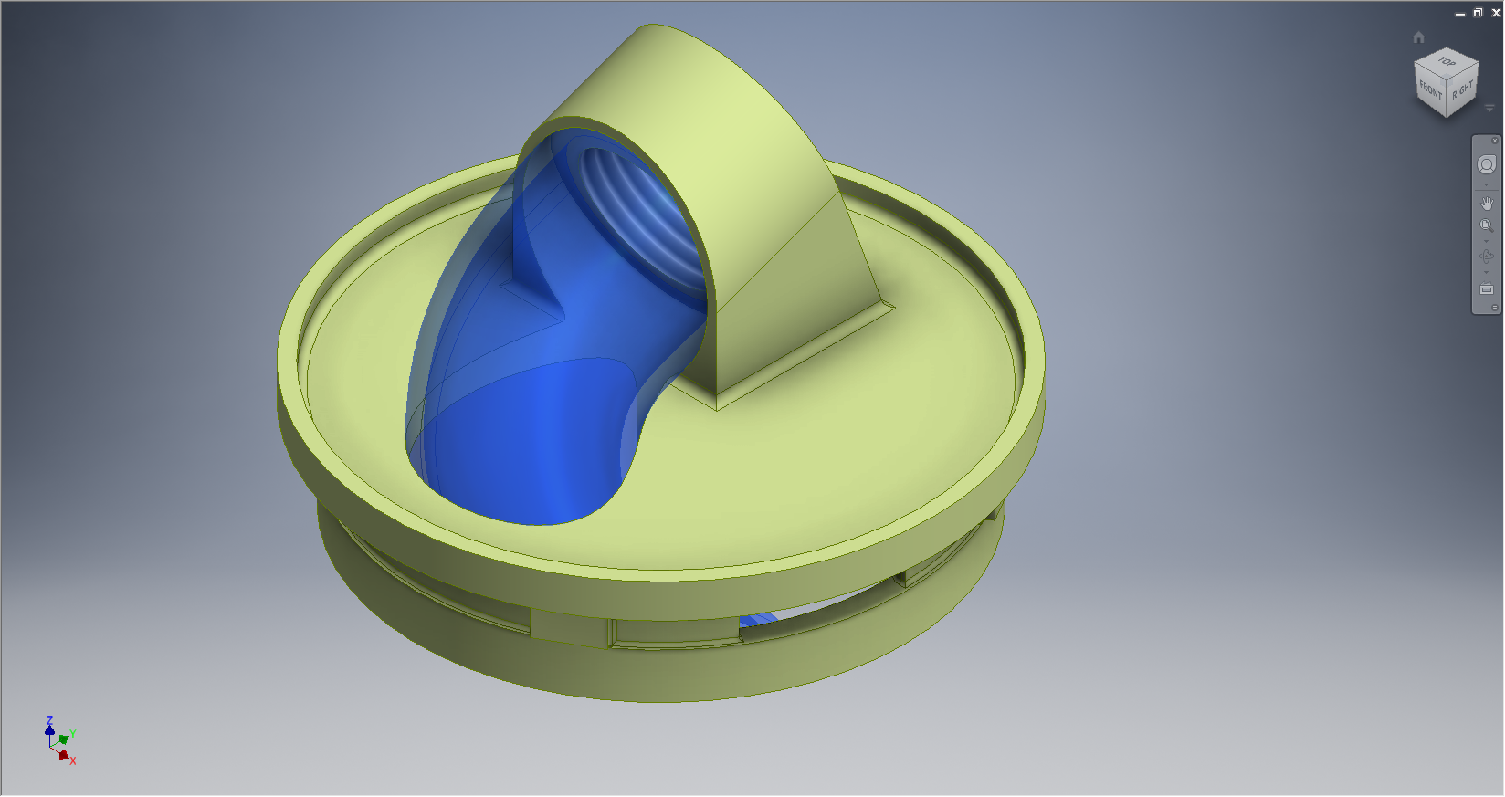
102-53391 Outlet Assy Haet Vent System Cockpit 2015-05-31_17-25-10

102-53391 Outlet Assembly: Heat & Vent Cockpit

2015-06-08_19-43-36 2015-06-08_19-46-35

102-33338 & 102-58181 Landing Gear Fairing Door Strut.

North American P-51 Mustang Project: Ordinates

NAA P-51 B/C/D Mustang

This is one of those projects that gets started and then for some reason gets put on the back-burner until now. One of the key reasons was due to the challenge of obtaining a good surface representation for the lower cowling for the P-51 B/C where I was having problems with the duct intake profile.

As usual I started with listing the ordinates in a spreadsheet and converting these to millimeters and extracting the X,Y.Z coordinates for further work in CAD.

I prefer to work in millimeters as I know that at so2015-05-30_19-31-32me stage the end profile may need micro adjustment which is so much easier to do using millimeter units.

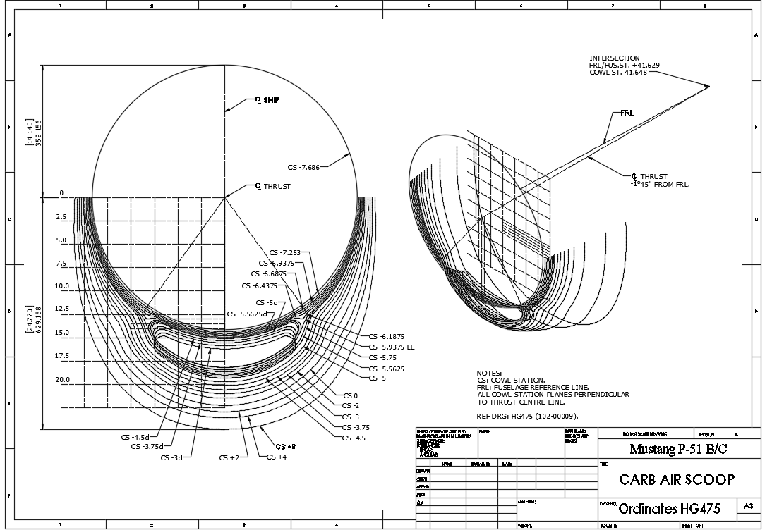
This is a scrap view from the NAA drawing showing the ordinates table and the contours.

Thankfully for this part most of the ordinates were quite legible with only a few requiring interpolation; which would be done as a consequence of developing the data in CAD.

As it turns out there were a few orphaned ordinates that for some unknown reason did not align with the CAD developed surfaces; so these were simply ignored instead of trying to invent a purpose for them being there!

2015-05-30_20-39-59The drawing (right) shows the end result of transferring the spreadsheet data into a CAD product. This drawing is simply a record of the translation process and surmises the ordinates in relation to the Thrust line and Fuselage Reference line.

The main body of the cowling did not present any real problems but the intake duct portion did.

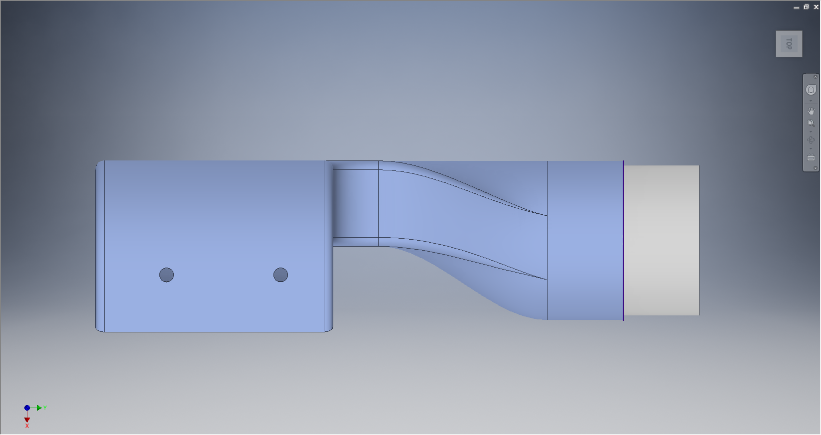
This area is less than 3 inches deep and is actually quite a complex surface; so any small deviation from exactness results in some crazy surface deformations. The original data tables are actually extremely good requiring only one small adjustment to get the result I was after…the trick was identifying which ordinates to use for the end profile and which ones we needed to check we have it done right.

After many (about a dozen) test developments of surface development and interrogation of the original data tables to ensure correct translations I eventually determined the correct ordinates and profiles to use to get this right.

2015-05-30_19-30-34

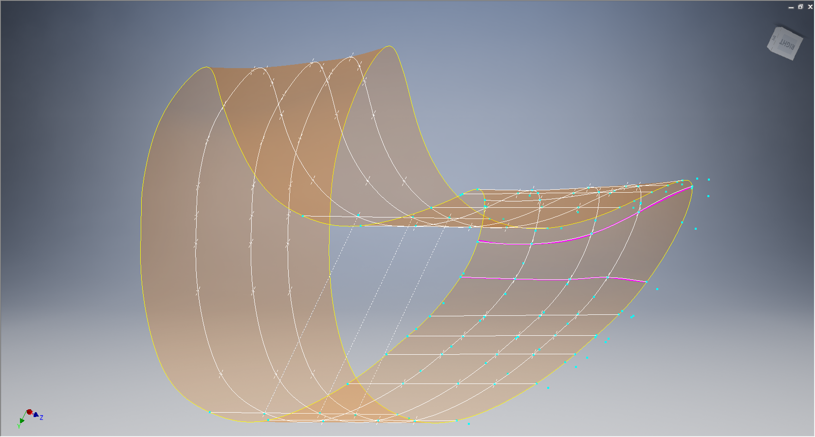
The resulting surface is based on the selected original ordinates with only one requiring micro adjust. In most cases the adjustment is simply an error in interpreting the sometimes indistinct values in the original data where a 6 could be an 8 or a 3 could be 5.

The 2 magenta coloured contours are generated profiles from a surface section cut overlayed on the ordinate controlled contours from the NAA tables which provides a check to ensure the surface conforms to the original design.

This surface will be converted to a T-Spline surface to facilitate final development.

It may be that this particular part does not warrant this level of exactness nor indeed the time expended in getting to this point. However it is a testament to the many fine designers of this era to be able to reproduce their work that was done to an extraordinary degree of accuracy.

Update Jan 2021: A comprehensive Ordinate/CAD package incorporating all known ordinate data points is now available for download. See this post for details.

Curtiss P-40 Kittyhawk/Warhawk

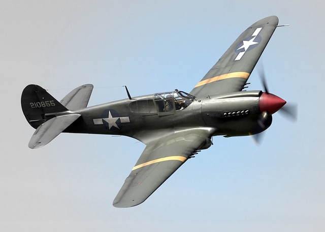
Curtiss P-40 Kittyhawk/Warhawk; the stuff of legends! flown by the infamous Flying Tigers and a remarkable if somewhat underrated aircraft.This is probably my all time favourite aircraft – perhaps influenced by the model I got when I was kid – which of course resplendent with ferocious sharks teeth really stirred the imagination of a young lad.

3902280811_6d029e71ac_o 4105135636_dbd0685269_o
I have in my archive several reels of scans for this aircraft, which I still have to review and document before I can start any meaningful research and development project. All my research projects are based on original manufacturers material, including manuals and specifications.

Solidworks: Wrap: Translation of 2D developed flat to curved surface.

Developing 3d models of historical aircraft is both challenging and sometimes frustrating, often requiring inventive, creative thought to develop complex shapes commonly associated with aircraft designs.

Solidworks: Wrap: Translation of 2D developed flat to curved surface.

One key aspect that has given me some grief in the past is when the fabrication drawings show a developed panel alongside the details of its final curvature. In a workshop one would just cut this plate and then form it on a predefined template to create the finished product.

This image illustrates a typical example of the sort of thing I am talking about. The large detail shows the flat pattern or developed profile with the top details showing the curvature required for the finished product.

I had tried various ways of doing this use the Flex and deform options to control the curvature within the dimensional limitations as noted – without success. I finally decided to try the Wrap command – essentially the same methodology used in the real world.

This Technote will describe the process I have adapted to develop these shaped forms.

For the purposes of keeping things simple I am not going to attempt the above but something a little easier.

19-02-2010 22-06-34

19-02-2010 22-08-16

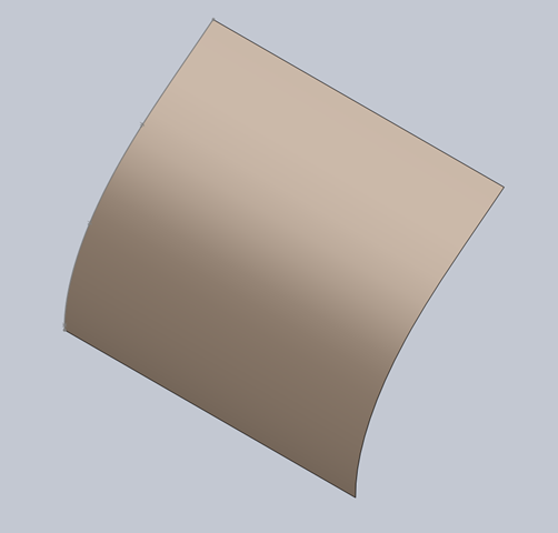
I created a spline and then extruded to give me a surface representing the finished curve.

19-02-2010 22-10-5319-02-2010 22-13-35

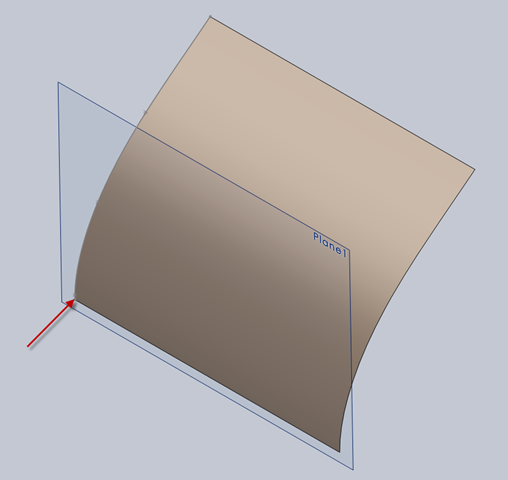
The next step is to create a plane tangent to the curved surface selecting the point at the bottom left corner. This is important; the plane has to be Tangent to the surface and a point selected that is coincidental with the alignment of the sketch. The sketch as shown is aligned with the bottom of the curve which is coincident with the datum for the plane. The reason why this is critical is that when the sketch is projected the lines deform to fit the surface which depends on the distance from the surface and the relationship between them – by selecting a coincident point where the sketch meets the surface then deformation is zero.

19-02-2010 22-20-50

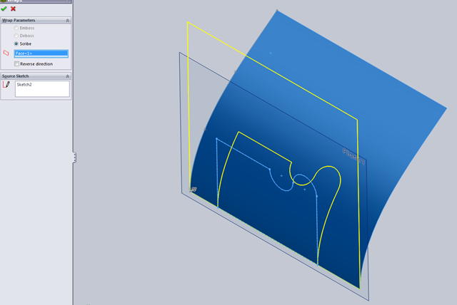
Inset>Features>Wrap – select the ‘scribe’ option and the 2d profile is ‘wrapped’ to the surface.

Note: cautionary comment: to check this methodology I did a measure on the left vertical line on the 2d sketch and checked it with the wrapped line on the surface – technically they should be equal – the 2d line measured 37.30194mm and the corresponding line on the surface is 37.29606mm – a variation of .00588mm – well within acceptable parameters.

This is where it gets interesting:

19-02-2010 22-30-43

19-02-2010 22-30-18

19-02-2010 22-28-20

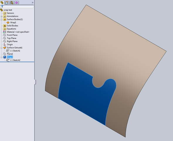
When you select ‘wrap’ in the feature tree the area of the wrap is highlighted and similarly when you select the ‘surface extrude’, but when you check the surface bodies we actually only have one surface!. So how can we progress this to separate the wrap area to enable us to finish the part?

19-02-2010 22-40-40Because the areas are separately selectable we can use the offset command with a value of zero and then select only the area we want….this creates a copy of the surface at the same location…all we need to do now is apply thickness and our part is complete.

So there we have it! A formed plate that conforms to the defined surface curvature and dimensionally with the 2d plan sketch.

Footnote: Placement of the tangent plane as I mentioned is important, but I suspect that thru experimentation various tangency relationships can be identified that satisfy all the necessary criteria.