.Technote: Bell P-39 Creating Wing Fillets.(Inventor 2017)
Wing fillets are probably one of the most complex aircraft items to model as they need to follow the curvature of both the wings and the fuselage shell. Invariably we have many offsets to contend with and variation in angular alignment of the flanges.
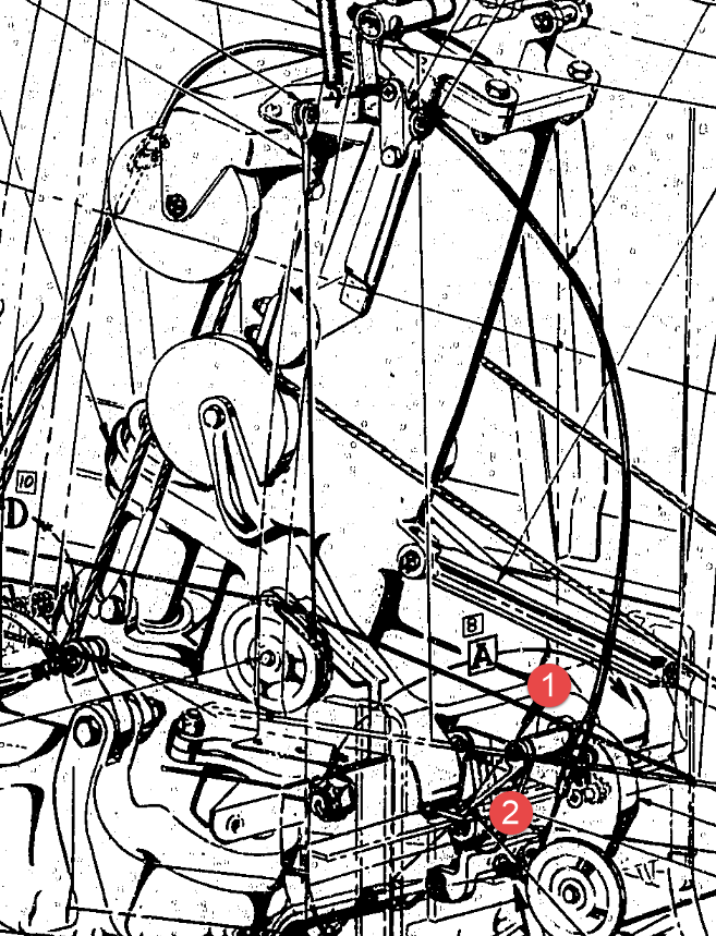
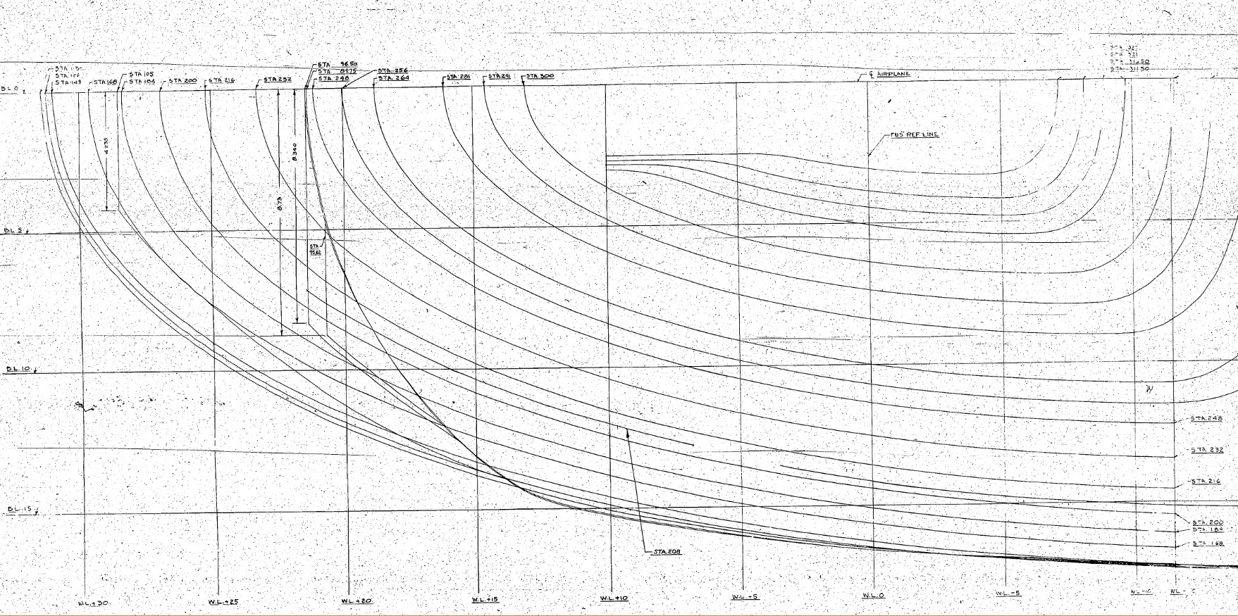
The following images are typical of the manufacturers drawings with an ordinate table listing the X,Y ordinates and angle of the flange at each point.


As usual we would start with marking out what we know; in this case the ordinates points from which we create the reference geometry.
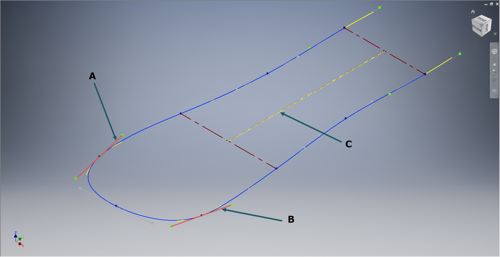
The reference geometry in this example is the 2 splines for the flanges connecting to the fuselage (left) and the wing (right) with a horizontal base line for the lower flange.
We then check the curvature of the splines to ensure we do not have negative curvature; adjusting the handles to negate this where necessary.
These Fillets are full of tangent and perpendicular dimensional oddities that can sometimes be a real pain to achieve satisfactory results .
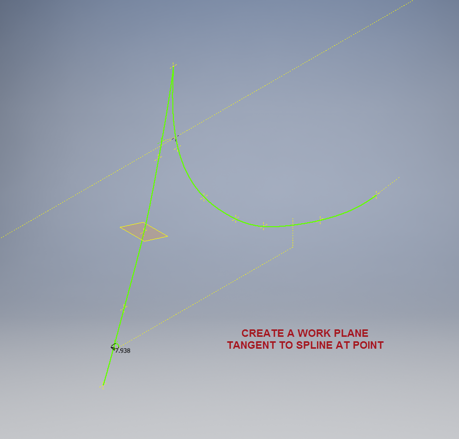
Previously we would create a work plane (tangent) at each node and individually sketch the required flange construction lines set to the correct angular value. This was a lot of work and a heck of a lot of sketching. Thankfully Autodesk have introduced some nice functionality to the 3D sketch environment in Inventor 2017 making this task so much easier with provision of logical constraining options and associations.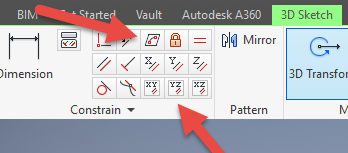
In Inventor we have various planar constraining options as shown. The top one is to constrain a sketch element to a surface and the lower ones are parallel constrain options to the main work planes.
We would still create the work planes tangent to each point as before; I have shown one for clarity, then we simply move straight into the 3D sketch environment to model all the flange construction lines.
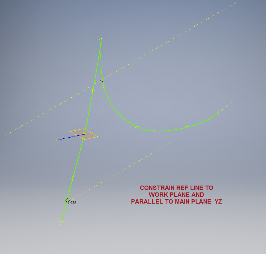
We first need a reference base line constrained to the tangent spline work plane and also be parallel to the main work plane YZ.
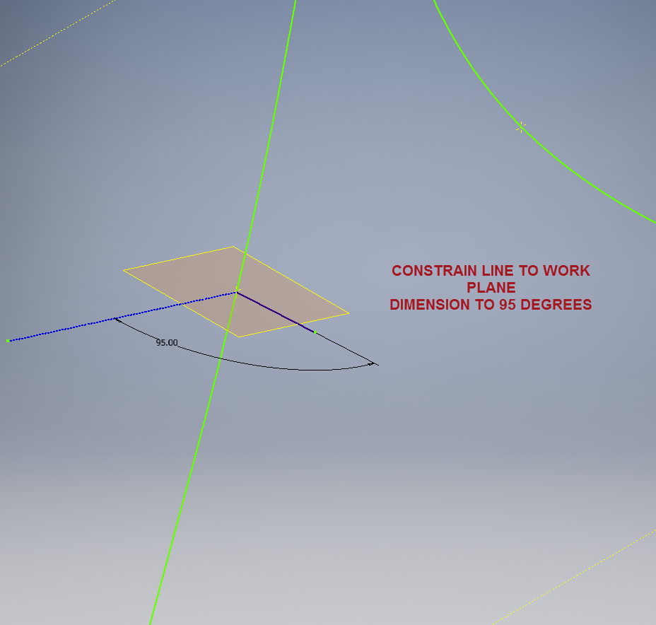
We then sketch the flange line, constrain to the tangent spline work plane and dimension to the reference line as shown at 95 degrees.
It really is a simple case of drawing a few lines and just using the planar constraint options to ensure correct tangency for developing the flange guide lines. Furthermore you don’t even need to project geometry from the 2d sketch as you place the line it will automatically connect to a point on the 2d sketch.


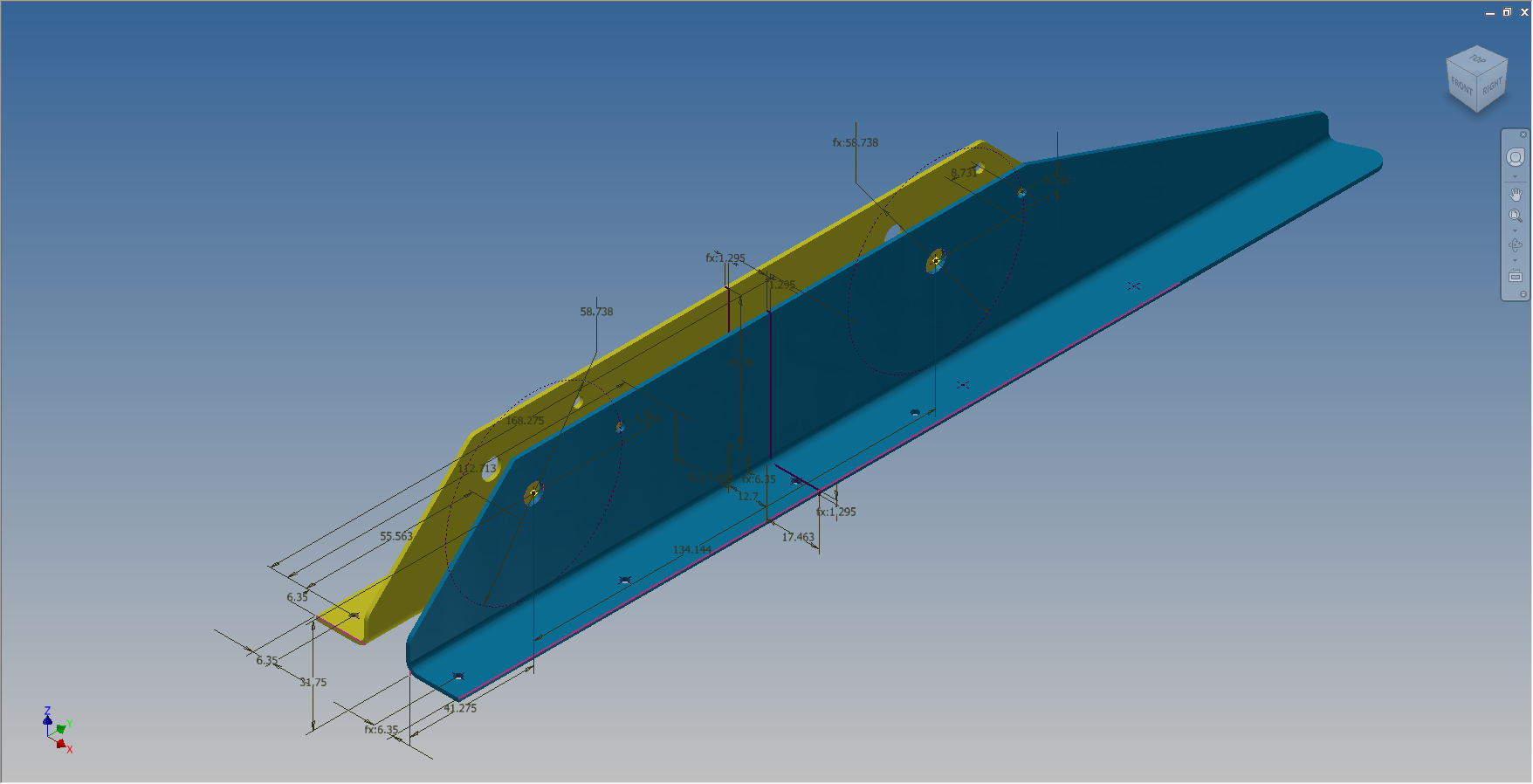
We continue doing this for all the ordinate points as shown then surface loft the flanges and apply a surface patch to create the main body. I should note that the surfaces shown have already been trimmed to the extents of the part.
It is very tempting at this stage to stitch and then thicken to achieve the finished part, however in my experience occasionally the transition of sharp corners introduces anomalies along the edges which can be negated if we first apply a fillet prior to thickening.
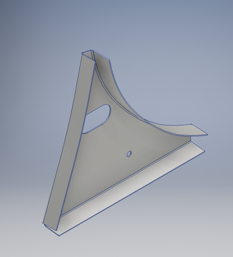
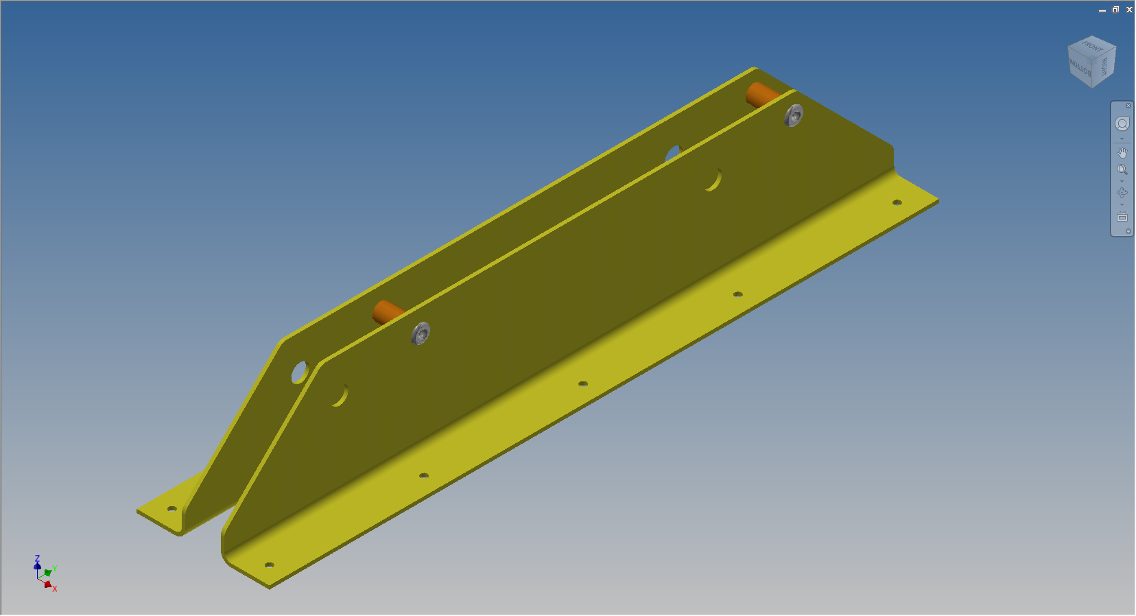
To finish the part after thickening, I converted to a sheet metal part and added a flange to the base at 7.5 degrees, a few holes and that’s it done. There are some flange holes still to be modelled which will be done later when the other connecting parts are modelled and checked for alignment in the assembly.
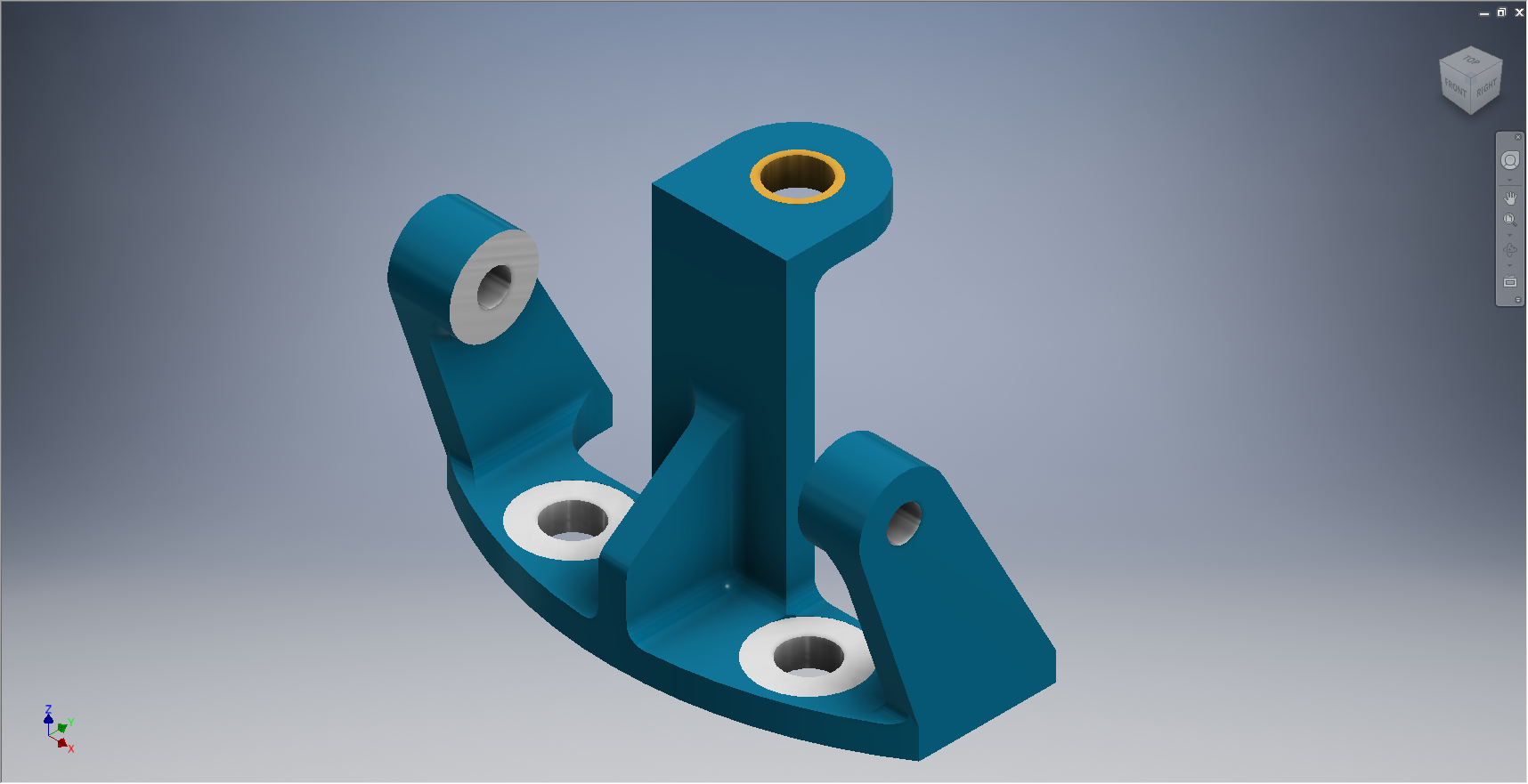
Progress Update:
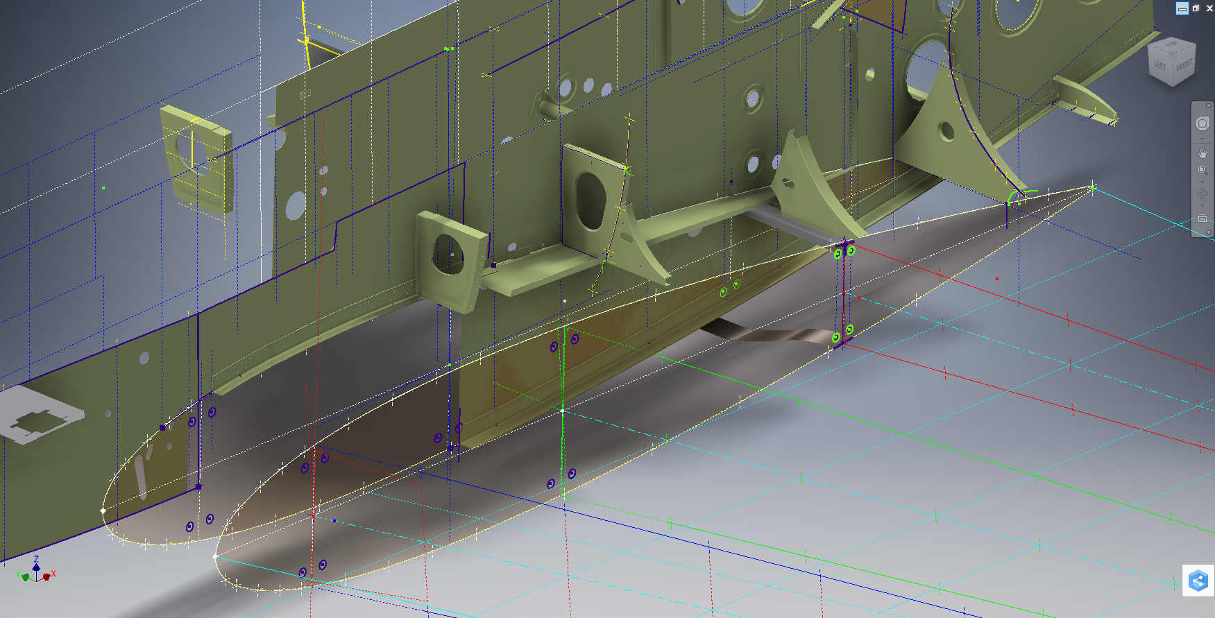
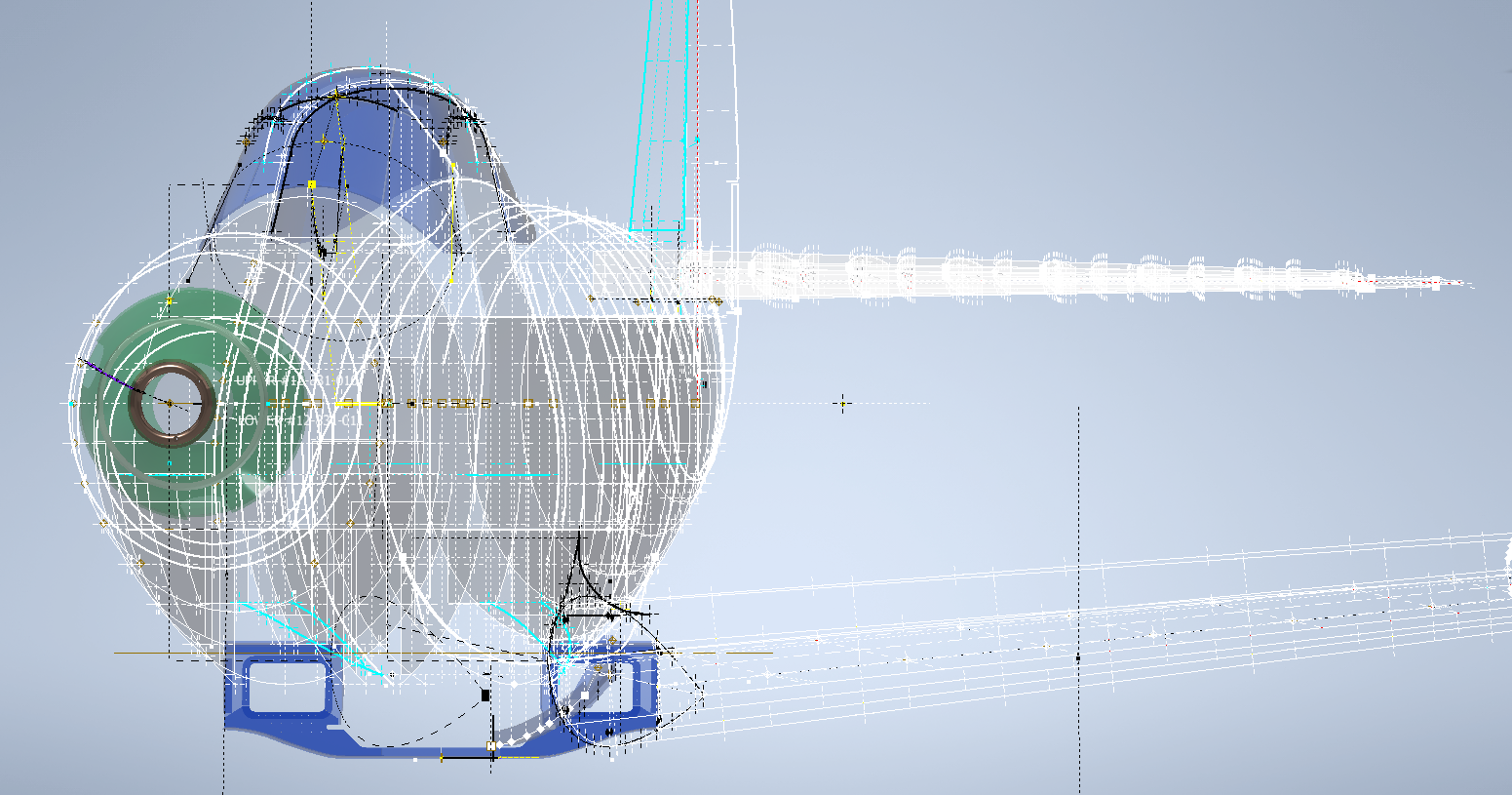
The following image shows a typical interface check between the P-39 wing and fuselage:
…and here the Radiator Intake Duct, preliminary alignment:
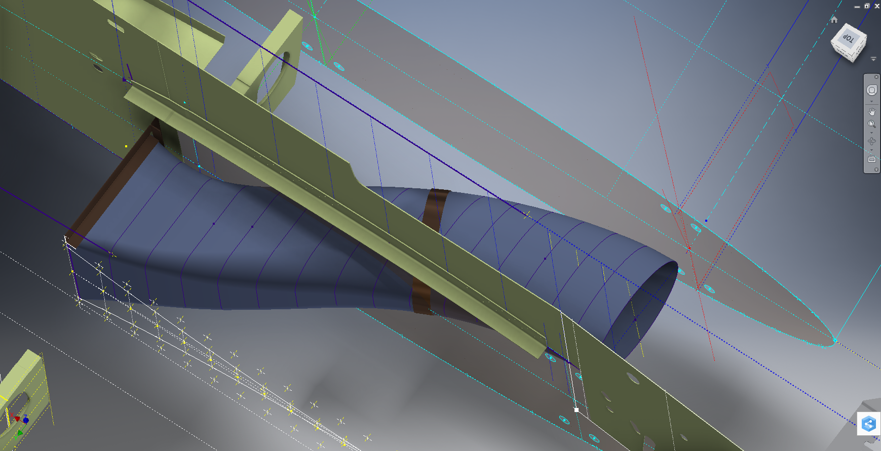
This radiator intake duct was an interesting development as the Bell chaps had provided both the tangential and the exterior dimensions at 2-inch intervals; on plan and elevation; which collectively are projected to form the profiles at each station. The white sketch at the bottom of the image shows these dimensions on the side elevation, with the curved lines depicting the tangent lines. I checked the curvature of this line and I only needed to adjust 2 dimensions by a minuscule amount to correct for negative curvature.
Update July 2022: New Revised P-39 Ordinate/CAD Dataset:

For all inquires please get in touch: hughtechnotes@gmail.com
 Technical drawings, detailing the specifics of your design can be critical for the communication both internally and externally. We can transform your 2D CAD or fully dimensioned legacy paper drawings to 3D Models using our experienced engineers to ensure drawings are 100% accurate and adhere to the most relevant standards and protocols.