NAA P-51D Mustang: Standard Part Models & Specs.
I have revisited the standard parts I have been producing for this project to verify that the information is correct and in compliance with the latest National Standards and specifications.
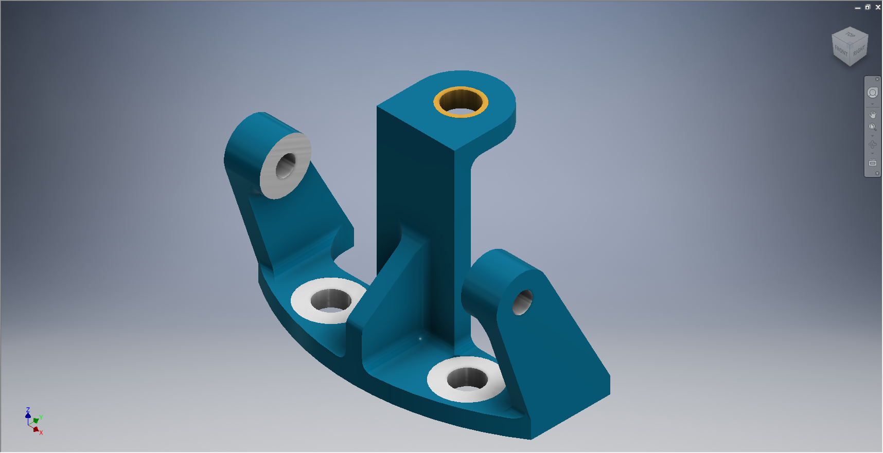
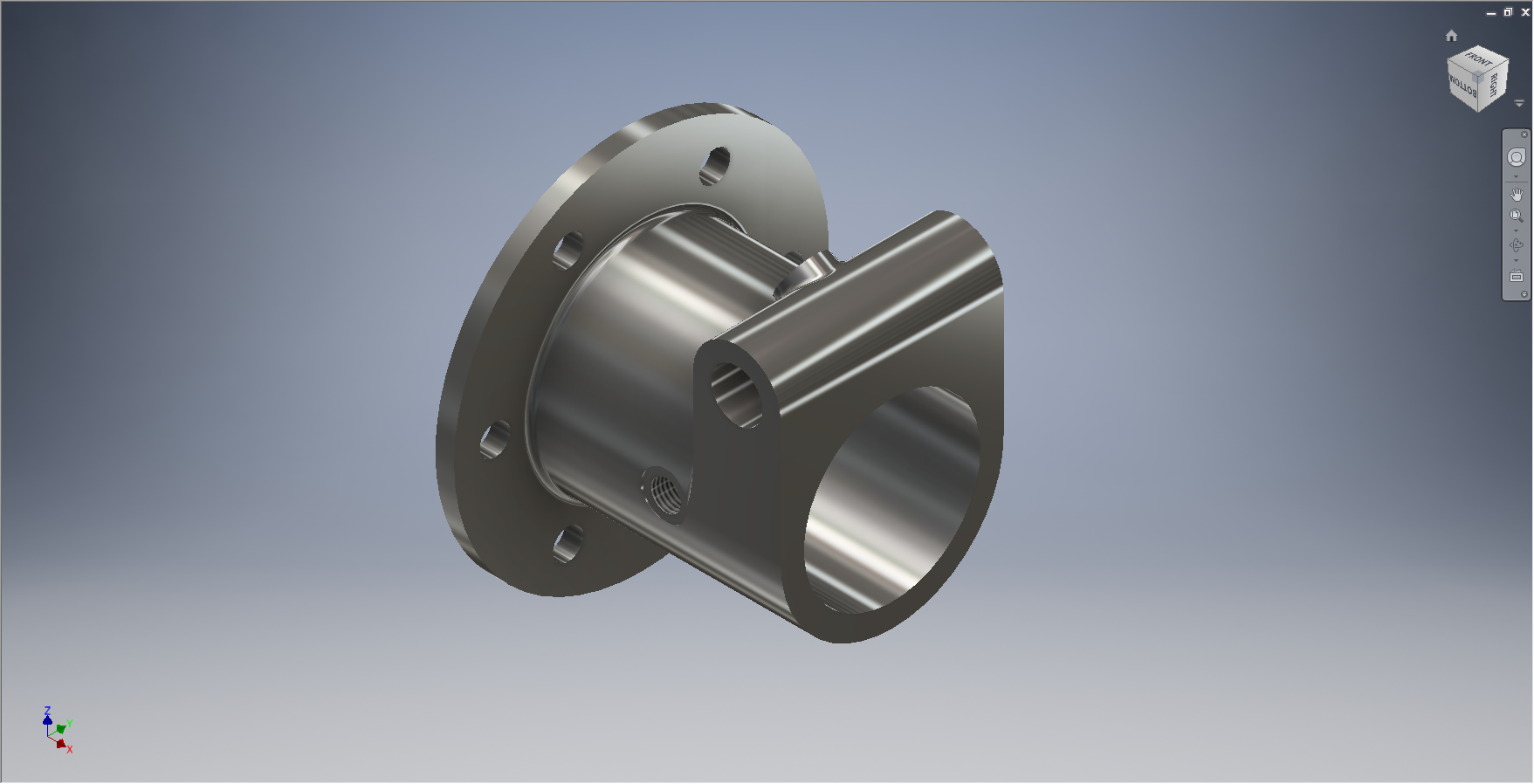
As mentioned previously I will be developing the parts for Bolts, Nuts, Washers, Pulleys Turnbuckles etc…in fact everything that constitutes a standard component pertinent to aircraft manufacture.
The parts specified for the P-51 are universal which have been updated over the years and superseded with new part numbers. These parts are suitable for reuse on other projects, in particular the forthcoming Operation Ark project.
To raise funds to support the “Operation Ark” project I have decided to make these 3D Cad parts library available for a small cost.


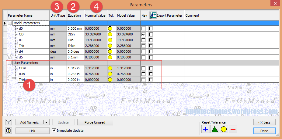
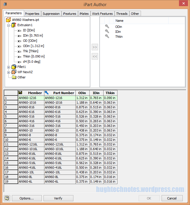
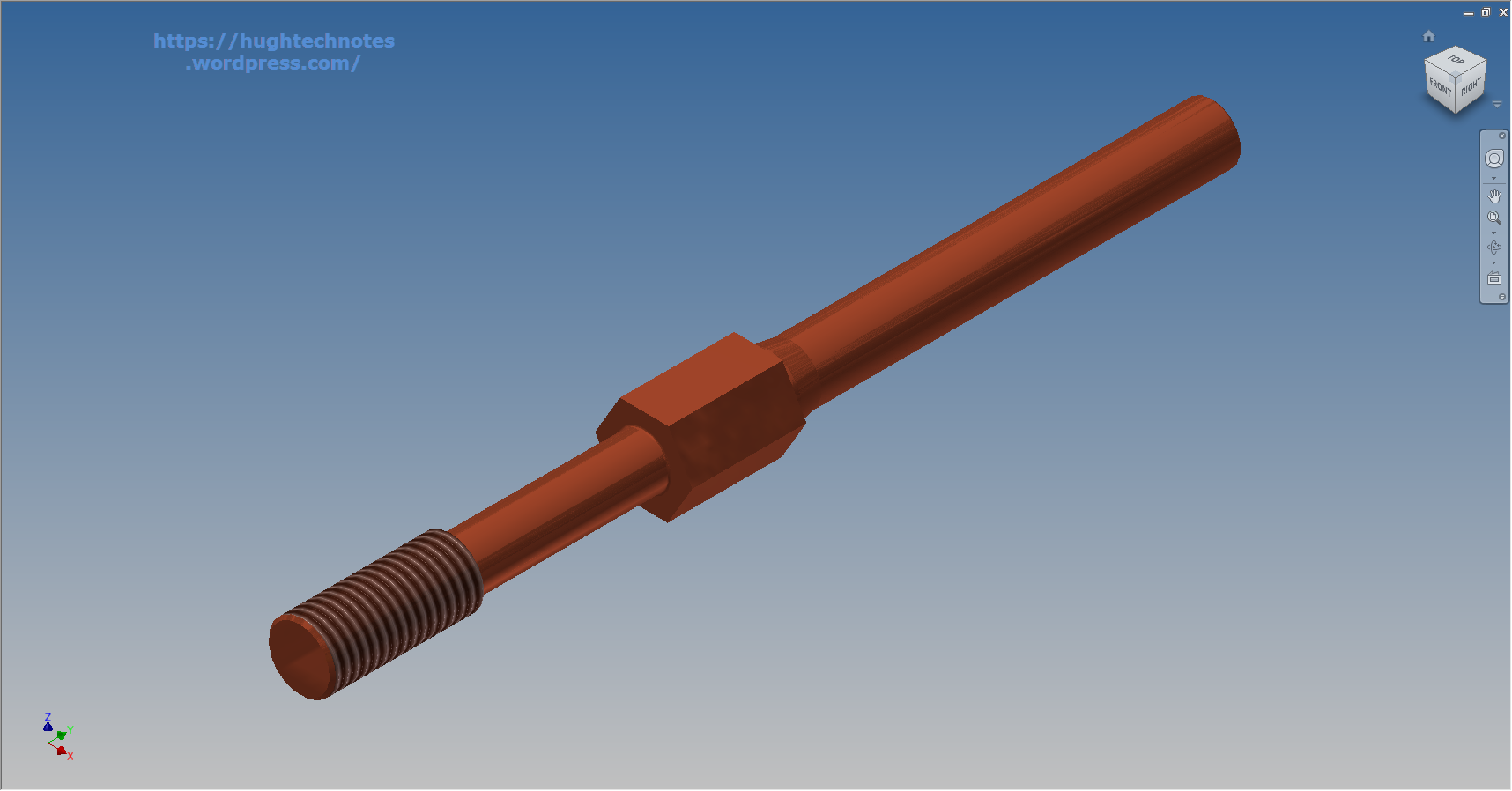
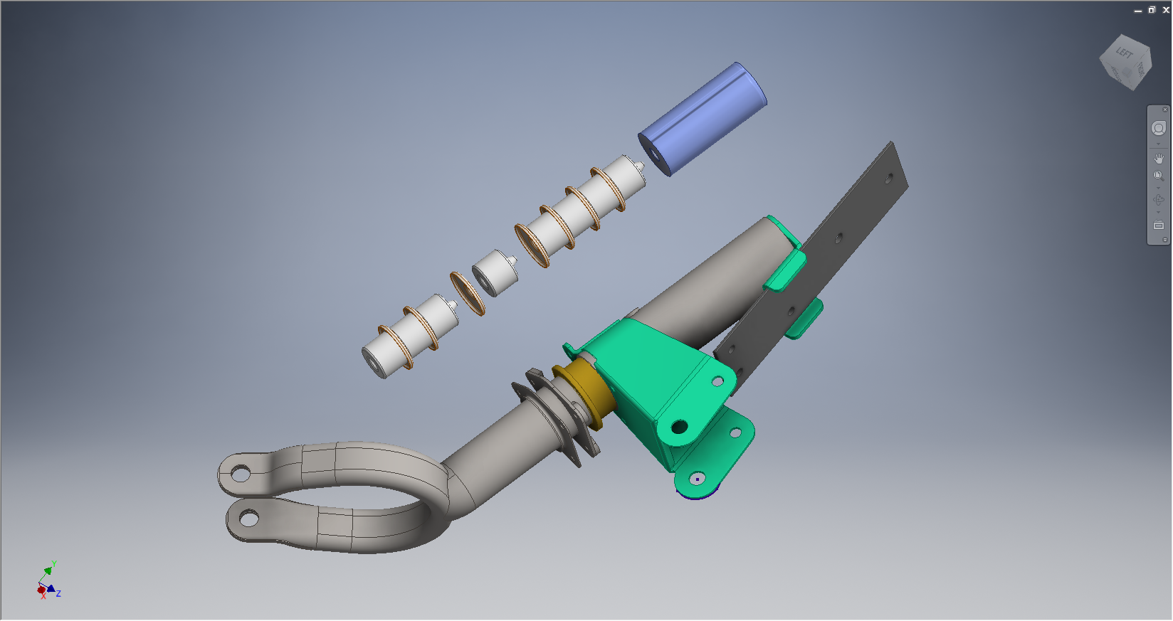
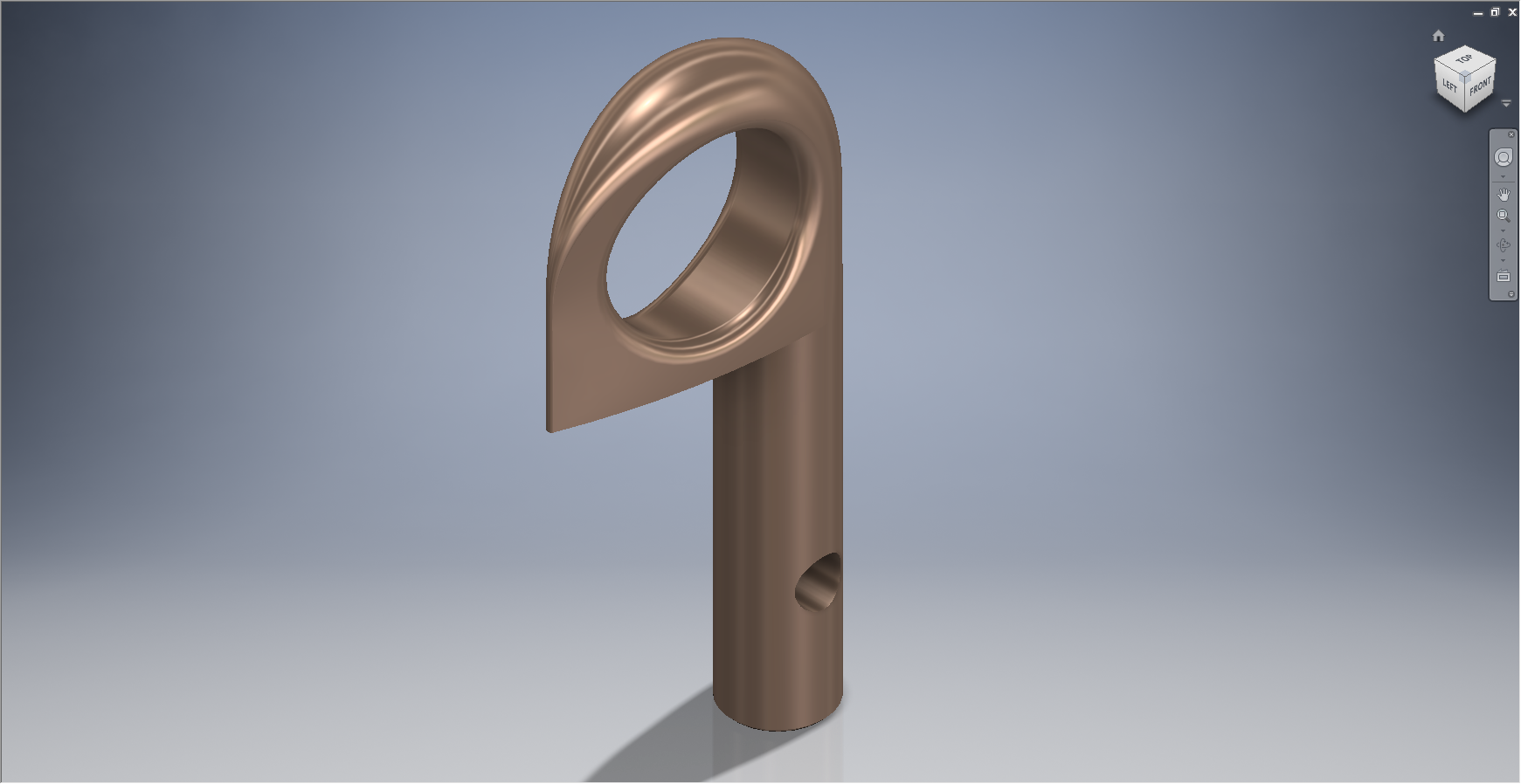
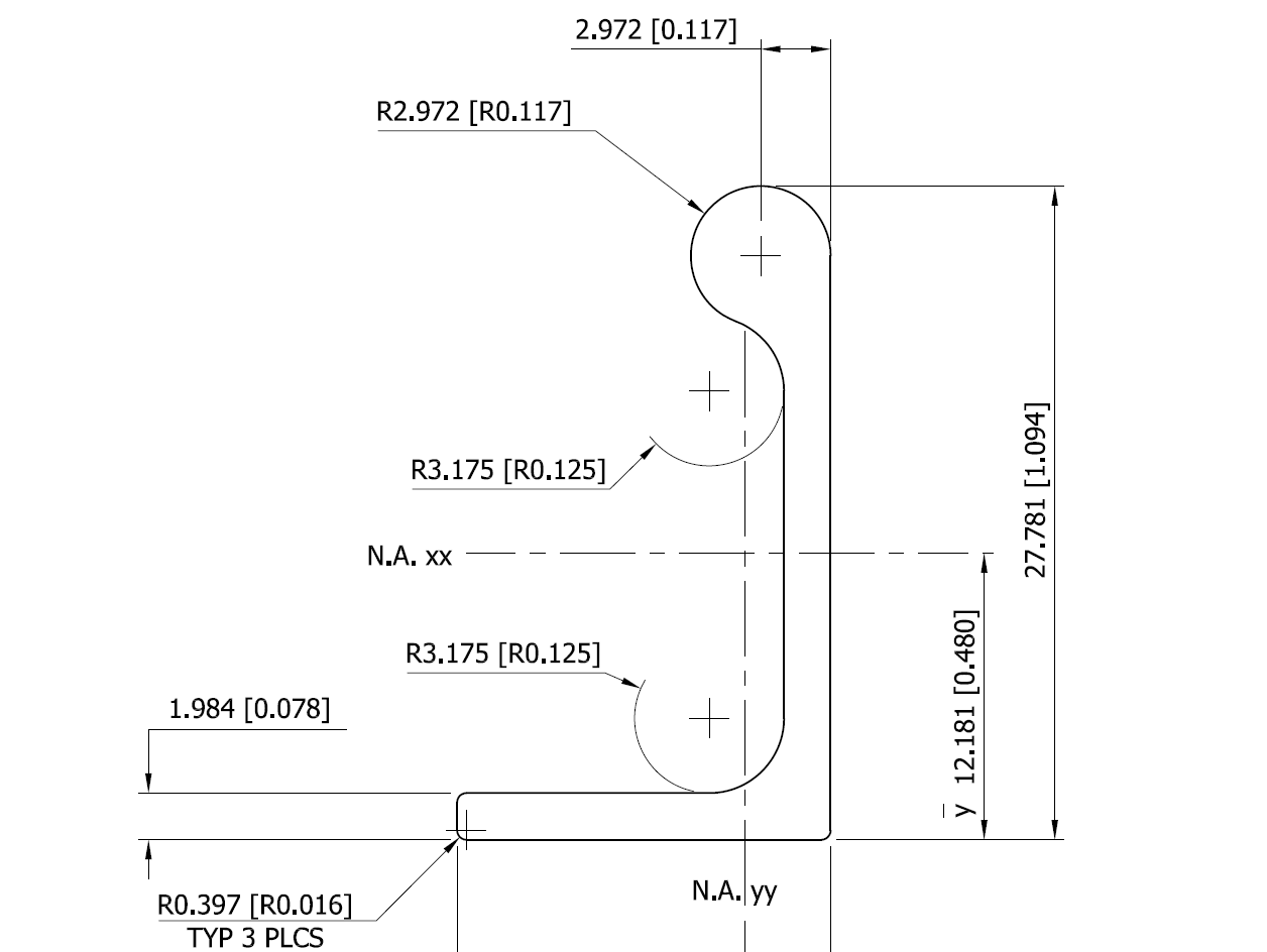
The part above is the Clevis End (Part #AN161), dimensioned in accordance with the MS21252P 2007 specification. All sizes are incorporated within an Inventor iPart model and in a separate spreadsheet.
“As from 2007 the parts covered by dash numbers shown on AN161 are canceled after 10 December 1971. Steel, carbon and alloy MS21252 parts are inactive for new design. Use only 17-4 PH stainless steel parts for new design and replacement for comparable alloy and carbon steel MS21252 parts and AN161 parts. The canceled AN161 parts and alloy and carbon steel MS21252 parts cannot replace comparable 17-4 PH stainless parts and should be used until existing stock is depleted.”
The CAD 3D model parts include both the AN161 parts number and the MS21252 Part number for comparison. The 17-4 PH number is not included in the model but is listed on the accompanying spreadsheet.
 Currently only a few parts are verified; please refer to the Resources page for updates as additional libraries are made available or if you have a special request for a library to be created then drop me a line.
For further details send an email to hughtechnotes@gmail.com