NAA P-51D Mustang: Document Management

NAA P-51D Mustang: Document Management

An update on the organisation of the document management and archive register.

The USAF Parts catalog for the P-51 is organised by assembly and sub assembly types. For the Tail Wheel assemblies we have one main installation assembly and two sub assemblies for the Shock Strut and Steering Mechanism as follows:

2015-07-02_00-29-57  2015-07-02_00-30-32  2015-07-02_00-32-05

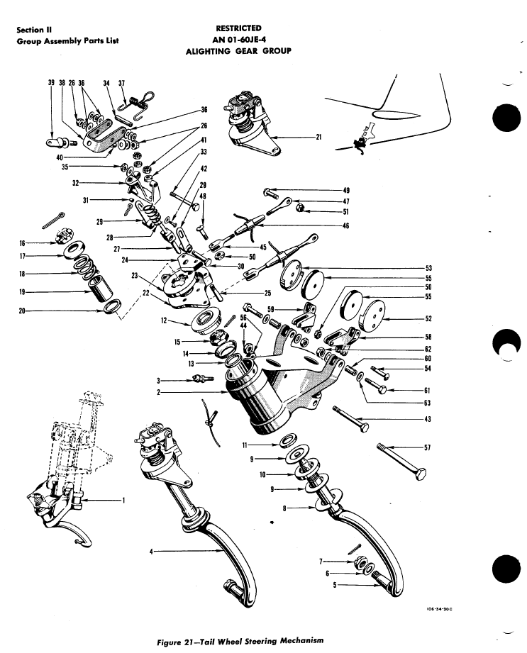
For the document register I have grouped the records and created separate worksheets that comply with the assemblies as setout in the USAF Parts List, listing the assemblies with a Category designation i.e TW-IN (Tail Wheel Installation) TW-SS and TW-SM.

2015-07-02_00-35-30

In the last column I have identified the NAA drawing by type; defining these as follows;

  1. Part: An individual drawing fully detailing a single part or item.
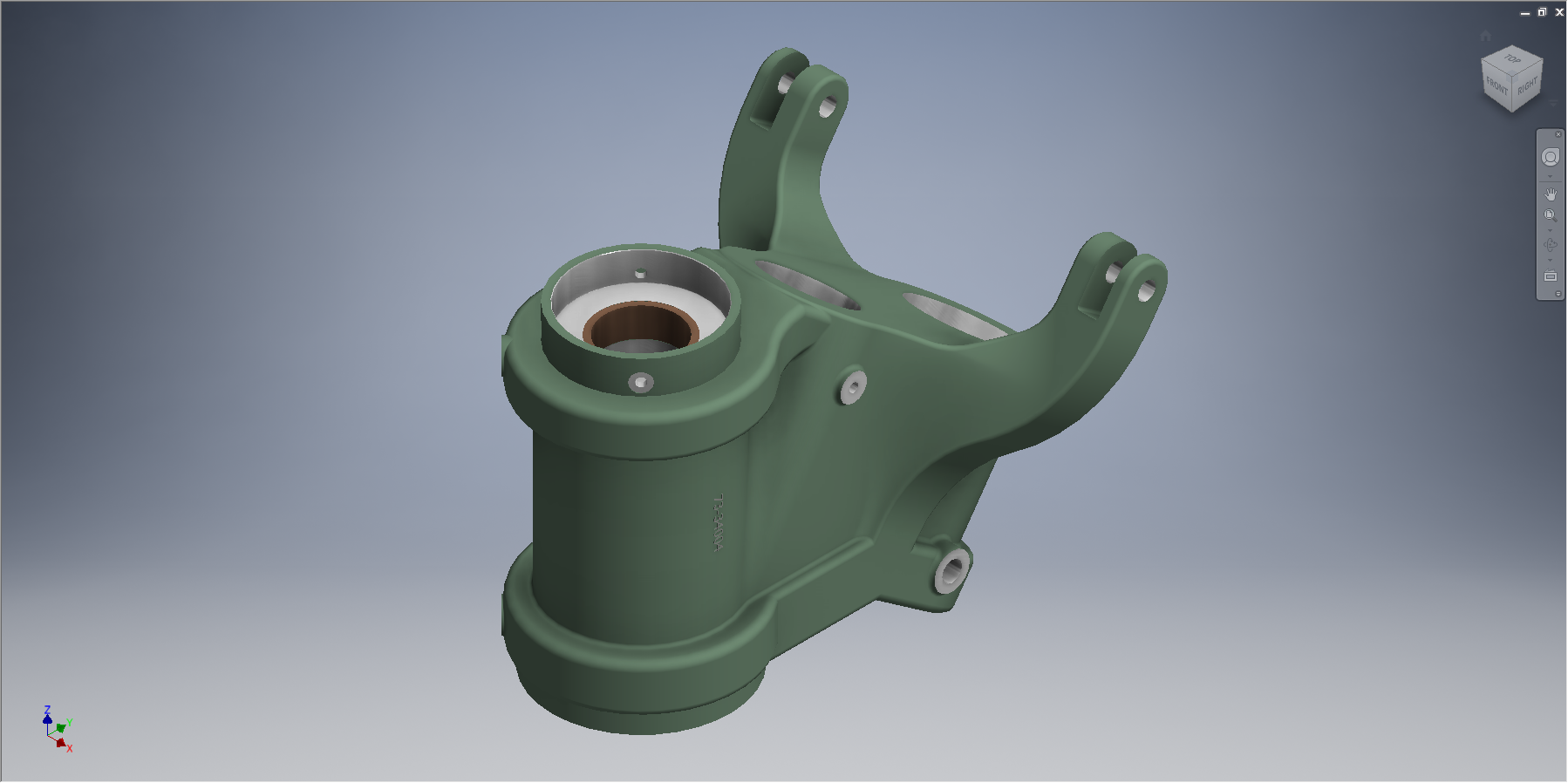
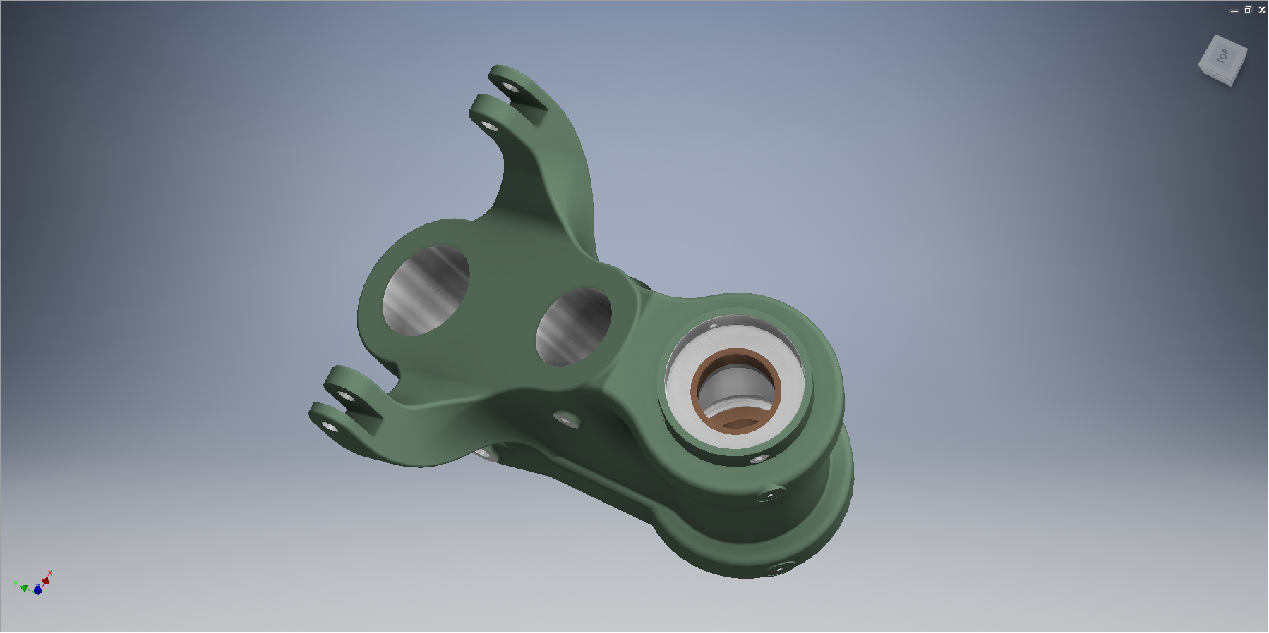
  2. Part Assembly: A fully detailed part drawing that includes additional fitted components like bearings, bushes or rivets.
  3. Main Assembly: A top level assembly listing individual parts, sub assemblies or components.

Note: The Part Assembly is technically a sub assembly which unusually comprise a fully detailed single part to which other elements have been added. Currently for this to work for me in the Cad environment I have maintained the part definition but modeled as a multi-part file. I may decide to change this to an actual Cad assembly file.

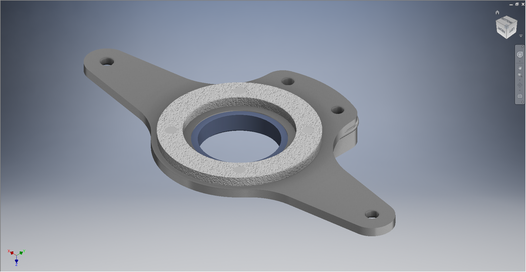
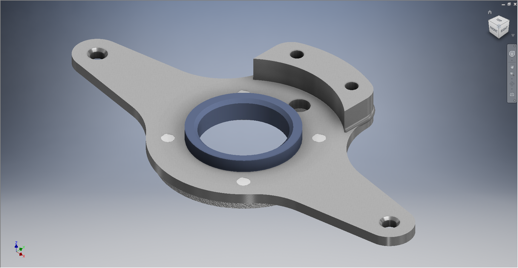
To clarify the above and ensure that all parts are accounted for I have created a sub listing of the contents for each Part Assembly as shown in the following scrap view:

2015-07-02_01-02-46

Some of the parts included in the Part Assembly are bushings, which are typically a press fit and reamed to a specified diameter. The bushing included in the Part Assembly is modeled to “as-fitted” condition, but as a matter of record I maintain a separate model file built to the “pre-fitted” manufactured dimensions.

I have also extracted a separate list from the USAF Parts List for the NAA standard parts from which I have identified the information I have in the archive and the data I will need to source elsewhere.

2015-07-02_01-13-08

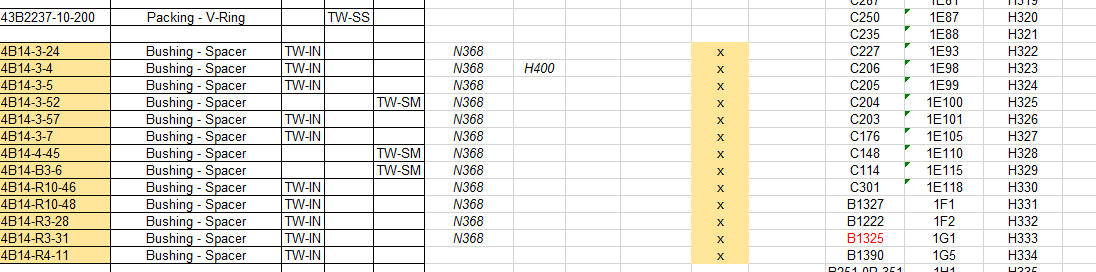
The NAA standard part drawings in many cases supersede earlier standards for which we have a reference listed. I have these listed in this spreadsheet in 3 columns (on the right); with the first entry being the “Old standard”; the second as the “New Standard” and the final entry being the archive reference. I have had to do this as occasionally the drawings refer to the old superseded standards number.

At this stage I have all the records for the Tail Wheel assembly organised into manageable chunks of information so that I can track progress as marked and manage the eventual build of the final Cad model assemblies.

NAA P-51D Mustang: Tail Wheel Progress Update

NAA P-51D Mustang: Tail Wheel Progress Update

I’ve been busy building the 3d models and working through the vagaries of the Mustang P-51 Tail wheel assembly. This is a selection of the new parts built to date:

Mustang P-51 Spindle
#73-34004 Housing Tail Wheel Spindle
Mustang P-51D Spindle
#73-34004 Housing Tail Wheel Spindle
Mustang Idler
#99-34153 Support: Tailwheel Declutch cable idler
Mustang Bell Tail Wheel Door
# 97-34502 Bellcrank: Tail Wheel Door
#73-31114: Support: Tail Wheel Shock Strut
2015-06-23_14-51-42
#73-31114: Support: Tail Wheel Shock Strut
Mustang P-51
#97-34120 Mast Assy – Tail wheel steering
Mustang P-51
#97-34120 Mast Assy – Tail wheel steering

This last image is a photo showing the Housing for the Tail Wheel Spindle with the model in a similar orientation and finish for comparison.

2015-06-22_16-57-13           2015-06-22_12-21-05

For the latest version of these models please refer to this article.

FW 190 & Ta152: Ordinates

FW190 & Ta152H: Ordinate Study

1-Ta-152H-captured-FE112-Germany-1945-01

The FW190 & Ta152 was a very intensive project as I delved into the intricacies of the fuselage, wing and rudder ordinates for both aircraft; a study accumulating a mass of data.

In preparing the models I adopted a modular approach to the development breaking the assemblies down into manageable chunks of information that align with the Bremen construction assembly documents.

Every aspect of the available manufacturers data, specifications and third party resources have been very carefully scrutinized and incorporated into this build. Cross-referencing of even the smallest detail drawings can yield surprising, almost minuscule amounts of information, that can have an impact on the finished product.

Aviation Projects Drawing Comments  2015-05-31_21-46-45  2015-05-31_21-45-522015-05-31_21-45-27

It may seem inconceivable to attempt to build a model of this type down to an accuracy better than actual manufacturing tolerances. However; as I have probably mentioned before; working with SolidWorks or Inventor this level of accuracy is critical to a successful build.

These illustrations give you some idea of the progress I made with this study. Of course, the data sets for this aircraft are incomplete so a degree of interpolation based on the best available information was used where required.

Ta152 Ordinate Spreadsheet package for wings and fuselage available:

Ta-152 Wing Ordinates

Ta152H Wing Layout:

2019-02-09_13-55-38