Project: Mooney Mite 18
Recently, a friend asked me to develop a CAD model of the Mooney Mite 18 for an aerodynamic research project…which, of course, I was happy to do.
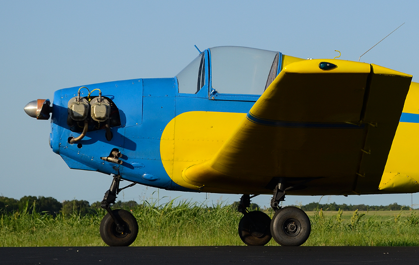
Mooney Aircraft, Inc. was formed in 1946 by Albert W. Mooney and Charles G. Yankey, both former executives of Culver Aircraft Corporation. The company soon marketed the Mooney M18 Mite, a low-wing, single-place, cabin monoplane designed for the general aviation market and involving extremely low operating costs.
The M-18 design goal was extremely low operating costs. The Mite is constructed mainly of fabric-covered wood, with a single spruce and plywood “D” wing spar. The wing aft of the spar is fabric-covered. The main structure around the canopy area is supported by a lightweight tubular frame.
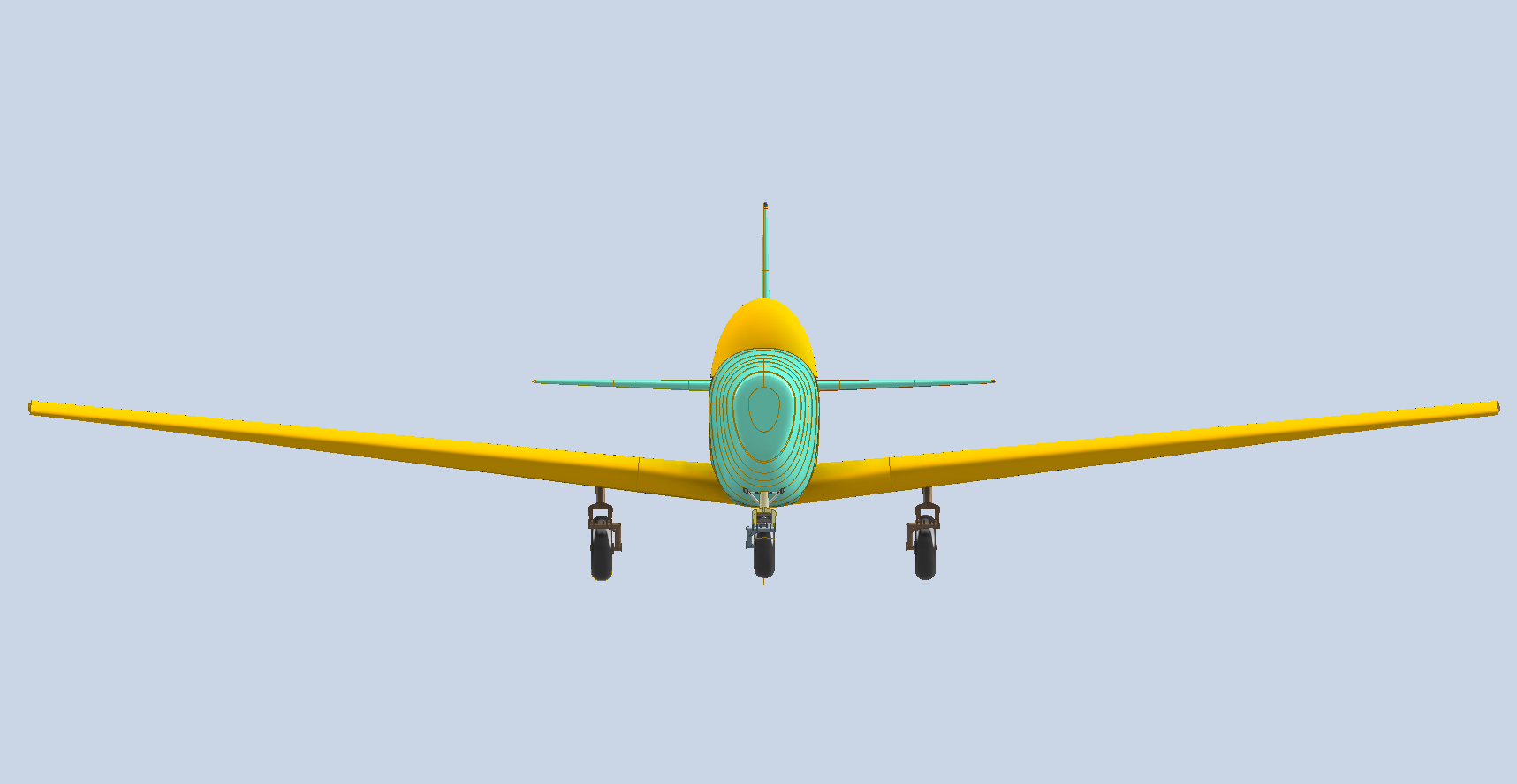
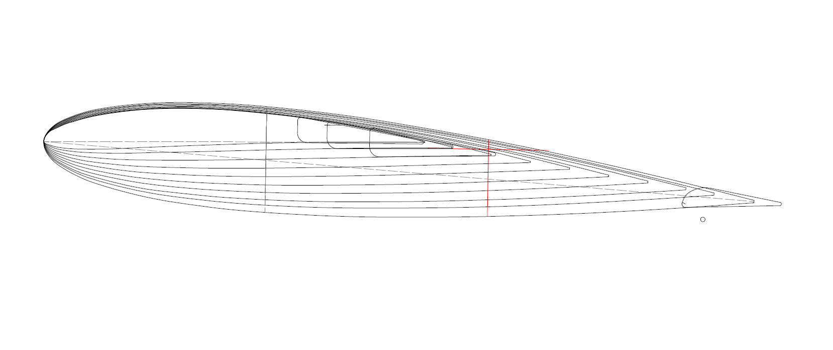
This aircraft also borrows many design features more commonly associated with the Mustang P-51, namely conic-section profiles for the fuselage, canopy, and cowl, alongside a Laminar-Flow wing. The wing, more precisely, is about 80% laminar; the root is a laminar airfoil, a 64215, but the tip is a standard NACA 2412
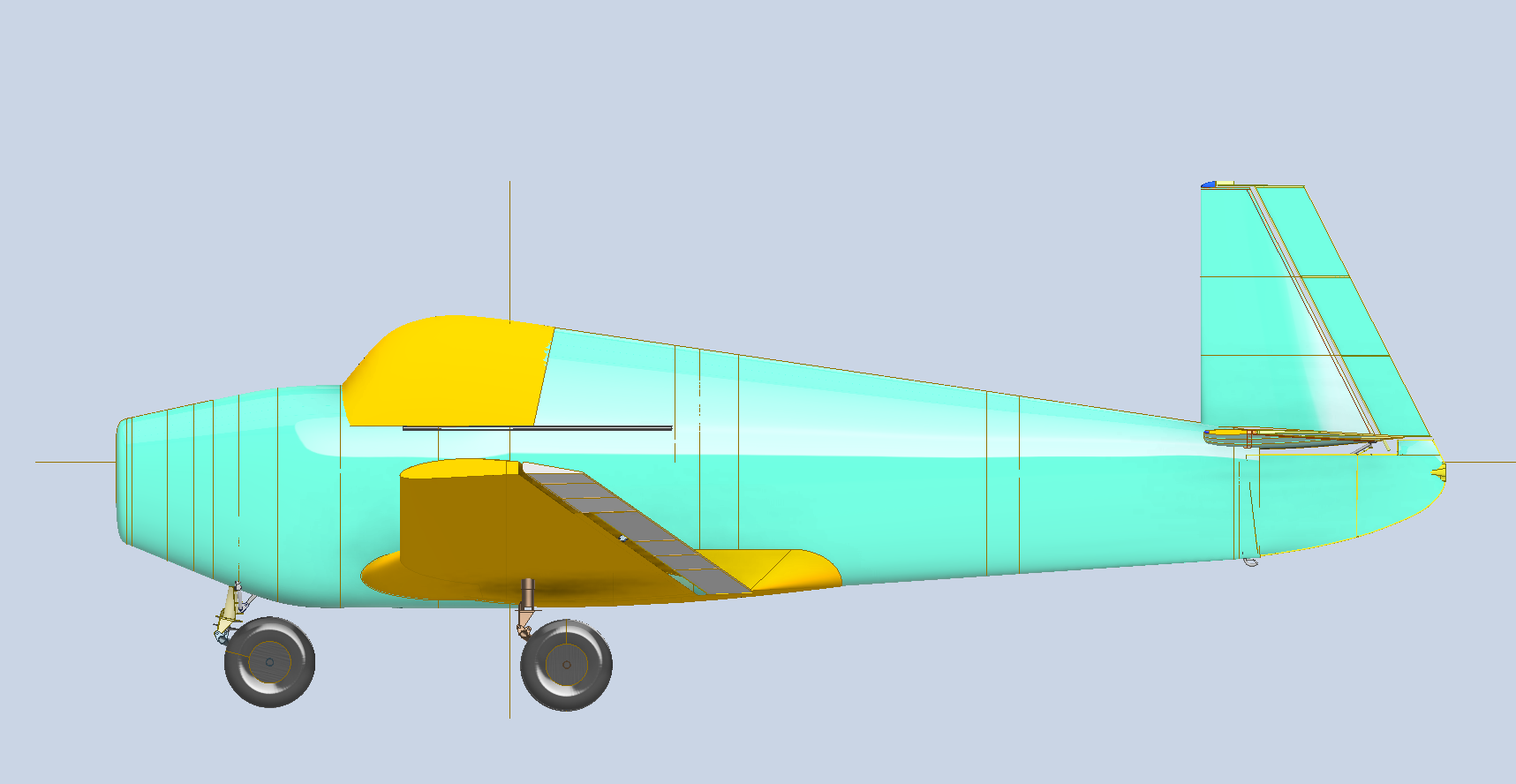
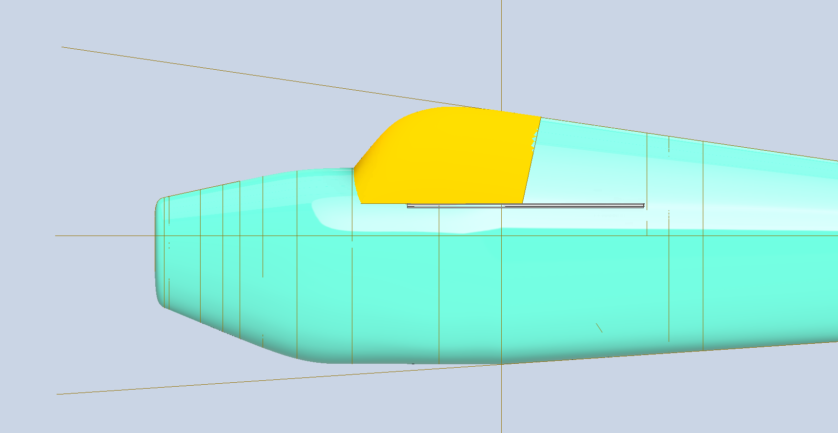
Evidently, a lot of design work was involved in developing the fuselage and wings, resulting in a very aerodynamic aircraft, but I am at odds trying to figure out what the heck they had in mind for the fuselage tail end. I shall come back to that, but first let’s look at the fuselage.
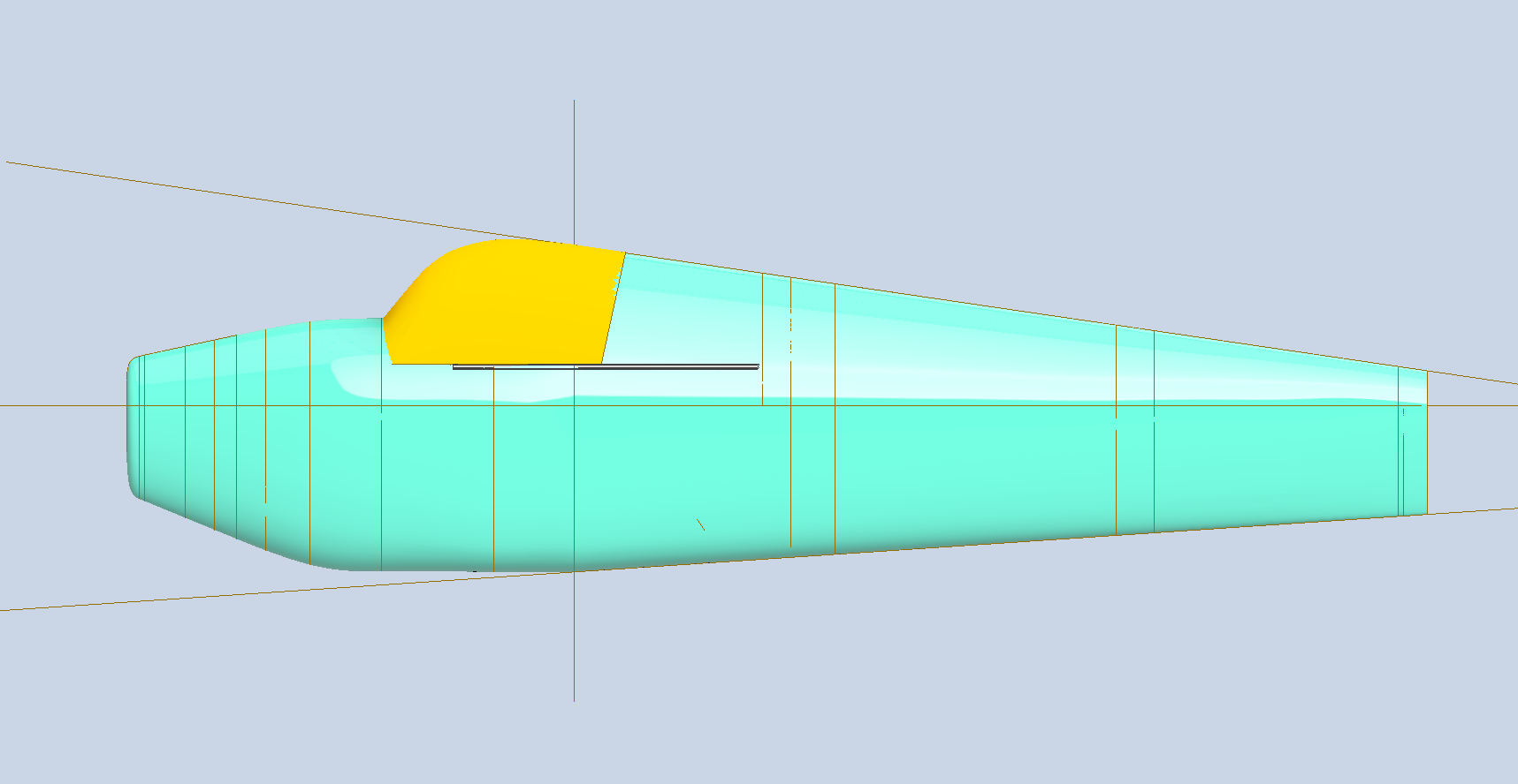
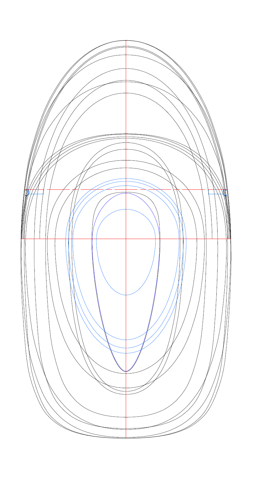
The vertical axis line shown at the aft end of the canopy is the aircraft datum line, 0,0,0. Aft of that line to Sta 113 the fuselage bulkheads are a straight loft. I actually checked this by examining the location of the top and bottom fairing lines (shown) and the centre butt lines that would be visible on the plan view.
As usual, I entered all known blueprint ordinate dimensions into a spreadsheet, and this time, I extrapolated the dimensions for the fairing lines: top, bottom, left, and right. These were then used as the dataset for a regression analysis in Excel to determine the best-fit line.
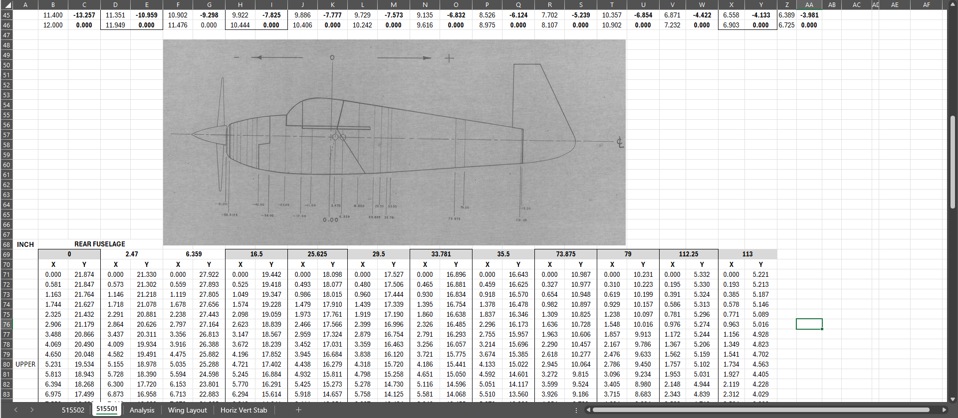
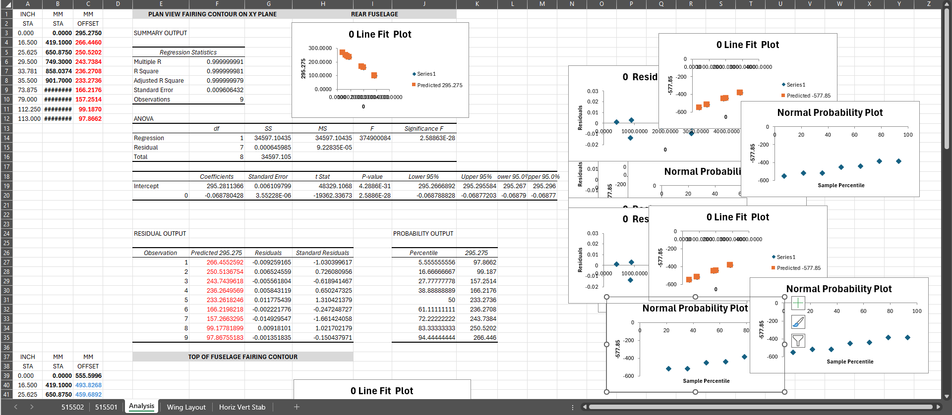
The values highlighted in red represent the vertical dimensions. After performing the calculations, the corrected results appeared in the second table, also highlighted in red. It’s important to note that the values are in millimetres, as this unit allows me to better understand the variations. What stands out is the level of accuracy in the blueprint ordinates, which remains well within acceptable tolerances, even for CAD. I did not alter these values in the CAD model because the resulting loft was quite good.
I often talk about curvature continuity to ensure a smooth transition throughout assemblies like fuselages; however, just forward of this datum point to the first bulkhead for the forward section, the two fuselage profiles share similar coordinates and therefore the transition will be a horizontal loft and not canted as before. This means there will be a distinct curvature adjustment where the fuselage fore and aft lofts meet at the datum. Essentially, we do not have curvature continuity at this point.
The forward fuselage loft is also worth discussing. Judging by the profiles of the bulkheads, it is possible to achieve good curvature continuity, but for some reason, the majority of the aircraft photographs I could find show another distinct angular break in continuity again…I guess it was easier to build.
Wings:
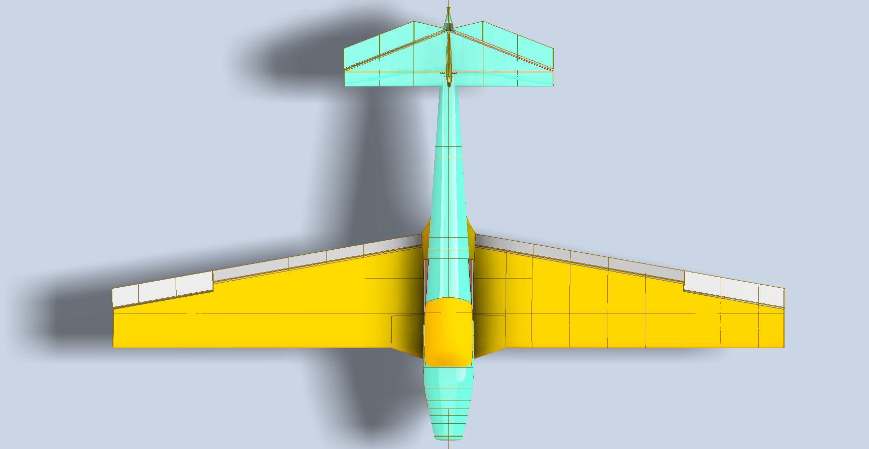
The wings are really interesting with Laminar Flow wing profiles and an extended leading edge at the wing root, remarkably similar design philosophy to the Mustang P-51. The wing also has a washout from the root to the wing tip.
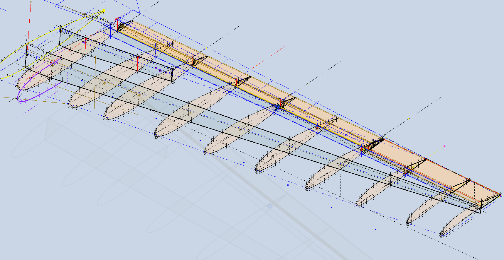
The resulting wing profile is actually very fluid when the wing ribs are correctly aligned. How that is done, well, for now I will keep that to myself. The blog I know from my email inbox helps a lot of people with their projects, but there is not a lot of reciprocal assistance, with very few donations to help me cover my overheads. So I won’t divulge everything, though it is clear in the available model CAD/Ordinate package.
The wing ribs are accurately profiled, and again, all ordinates are listed in the Excel spreadsheets. The Flaps and Ailerons also accurately dimensioned, and I had no problems aligning these with the wing.
Empennage and Fuselage Tail Section:
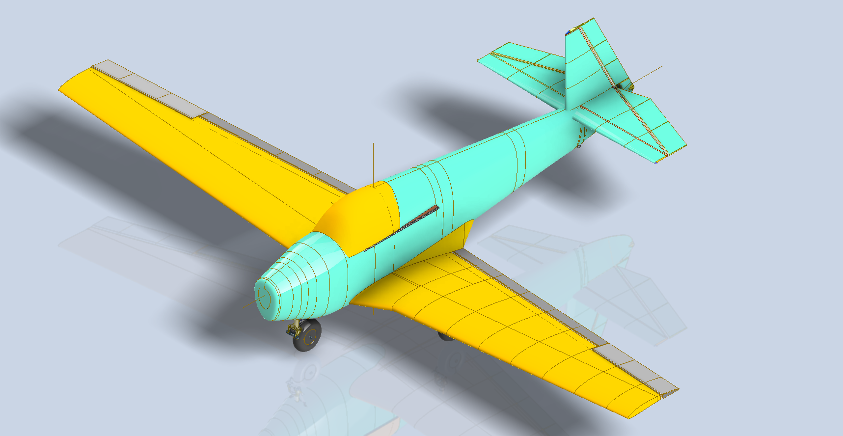
This area was a nightmare… for many reasons, but mainly due to a lack of location dimensions. The Vertical Stabiliser does include the location of the Horizontal Stabiliser, but their relationship to the fuselage is not dimensioned. So I had to work this all out by first developing supporting structures and aligning with brackets on the bulkhead at Sta 113.
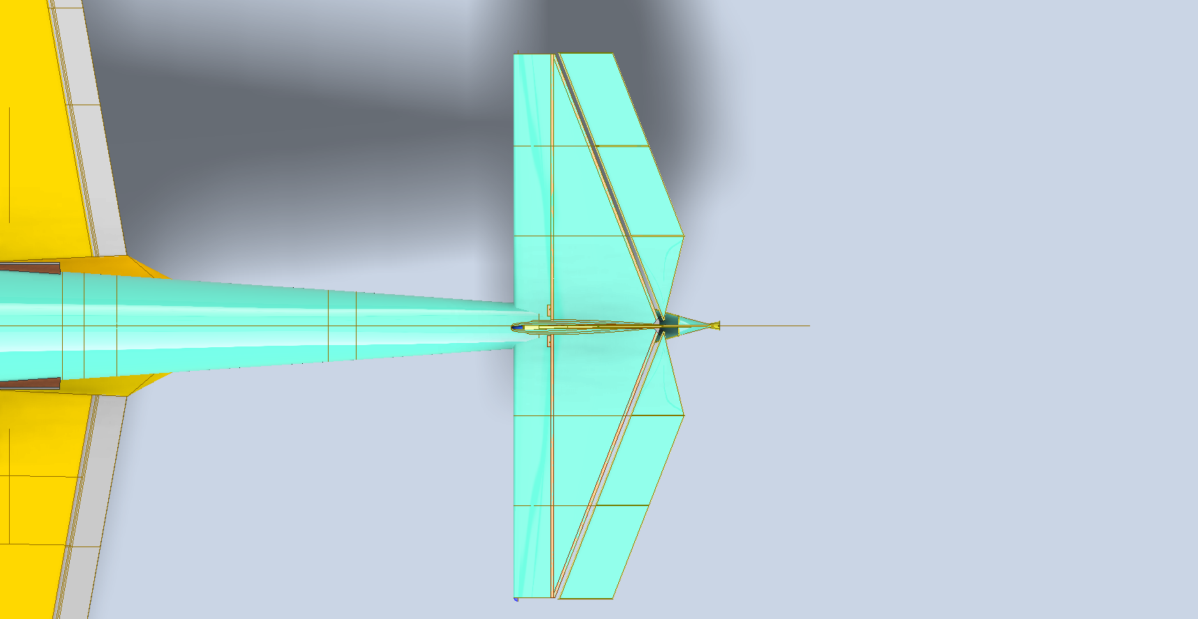
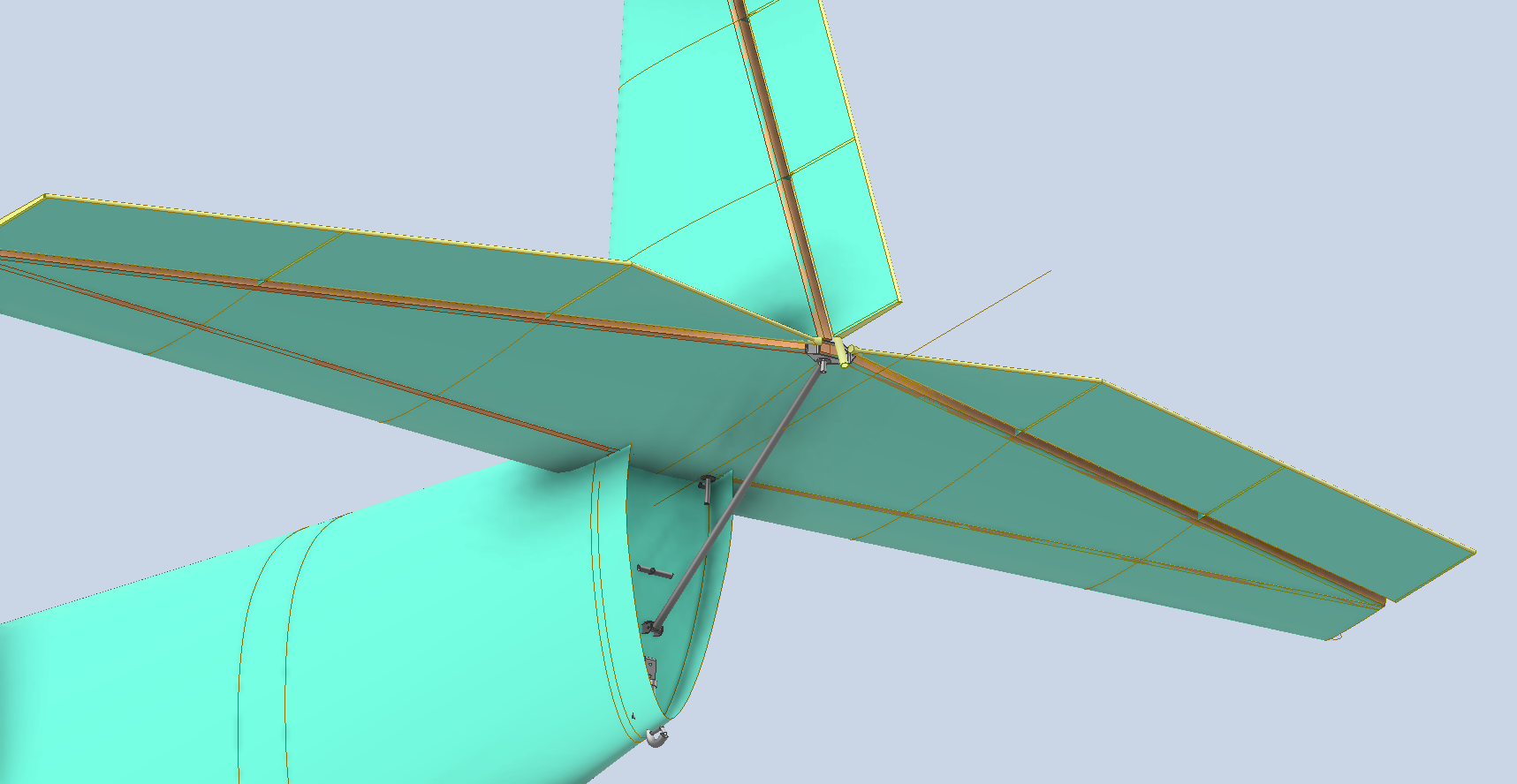
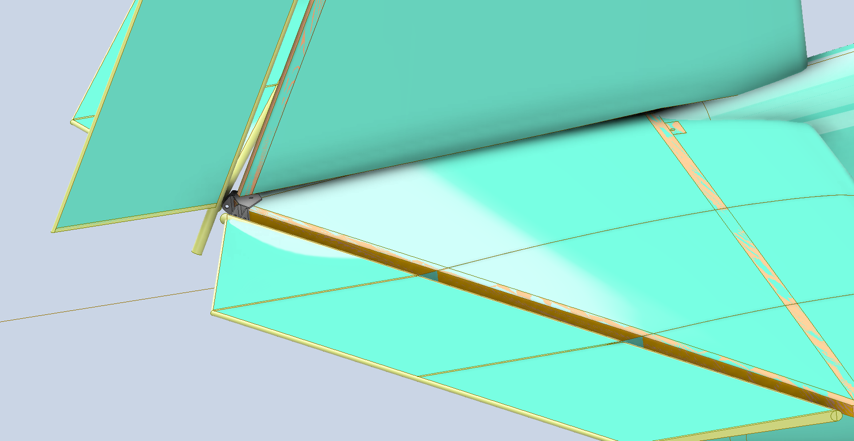
In the images above, you can see the partially modelled diagonal frame that supports the entire empennage. Interestingly, the entire assembly is secured with just three bolts. On top of this frame, there is a fabric-covered tubular structure that essentially forms the tail end of the rear fuselage. To get everything to work correctly, the brackets were sketched out from the Fuselage Bulkhead at Sta 113, the main support frame was partially modelled to locate onto those brackets, and then the Vertical and Horizontal stabilisers were located to the requisite fixing points on this frame. To check the dimensions of the Stabilisers and the frame, I created a few 2D drawings to ensure correctness.
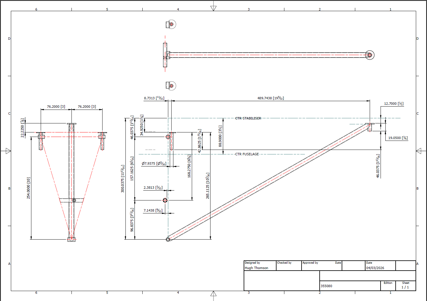
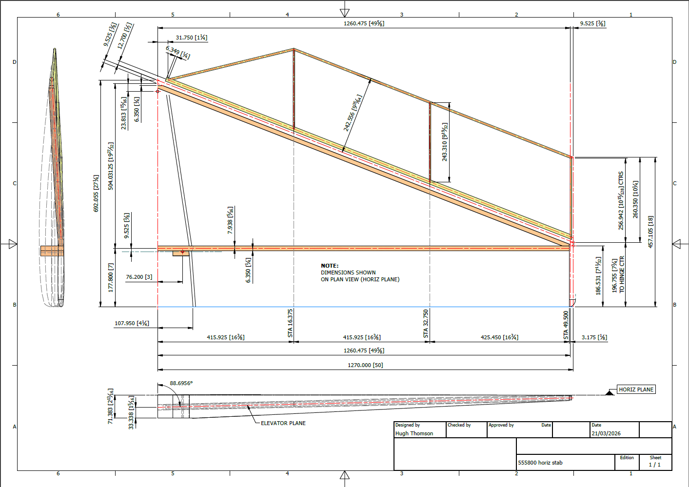
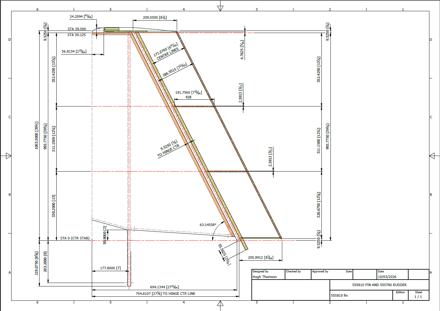
I should note that these drawings are not fully dimensioned; the primary purpose is to check the validity of the 3D model by ensuring the setting out dimensions and location of the fixing points are correct. Once fully assembled, all these components will at last be correctly associated with the fuselage.
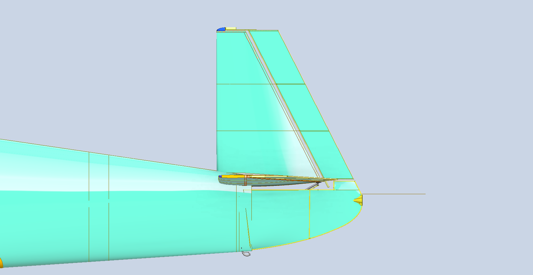
The nightmare portion is this fuselage tail end.
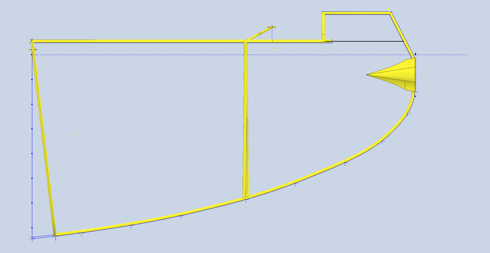
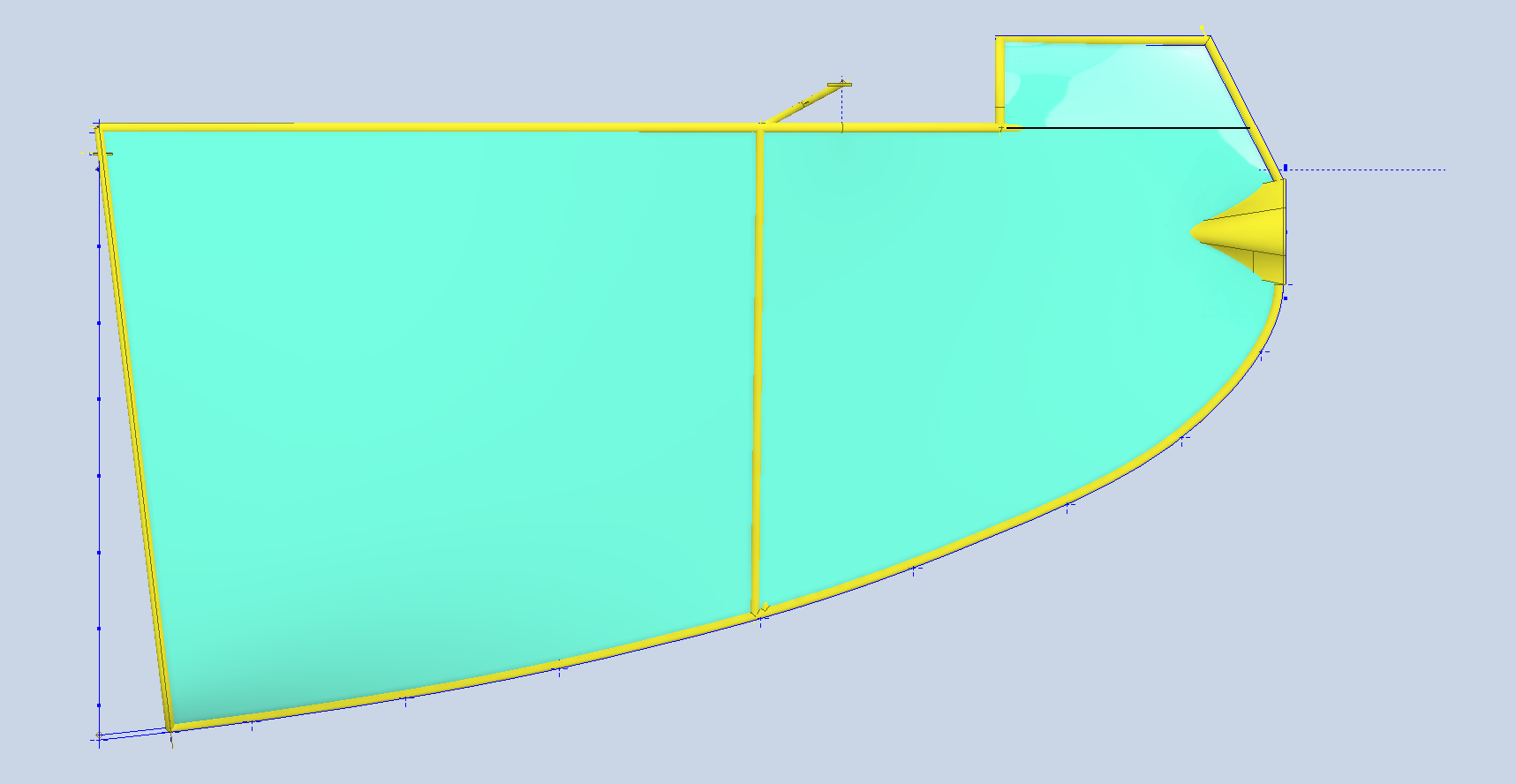
The main problem with this section is that dimensionally, nothing worked. It may simply be an out-of-date drawing or maybe a later revised edition. I don’t know for sure, but for some reason, the dimensions highlighted are not correct.
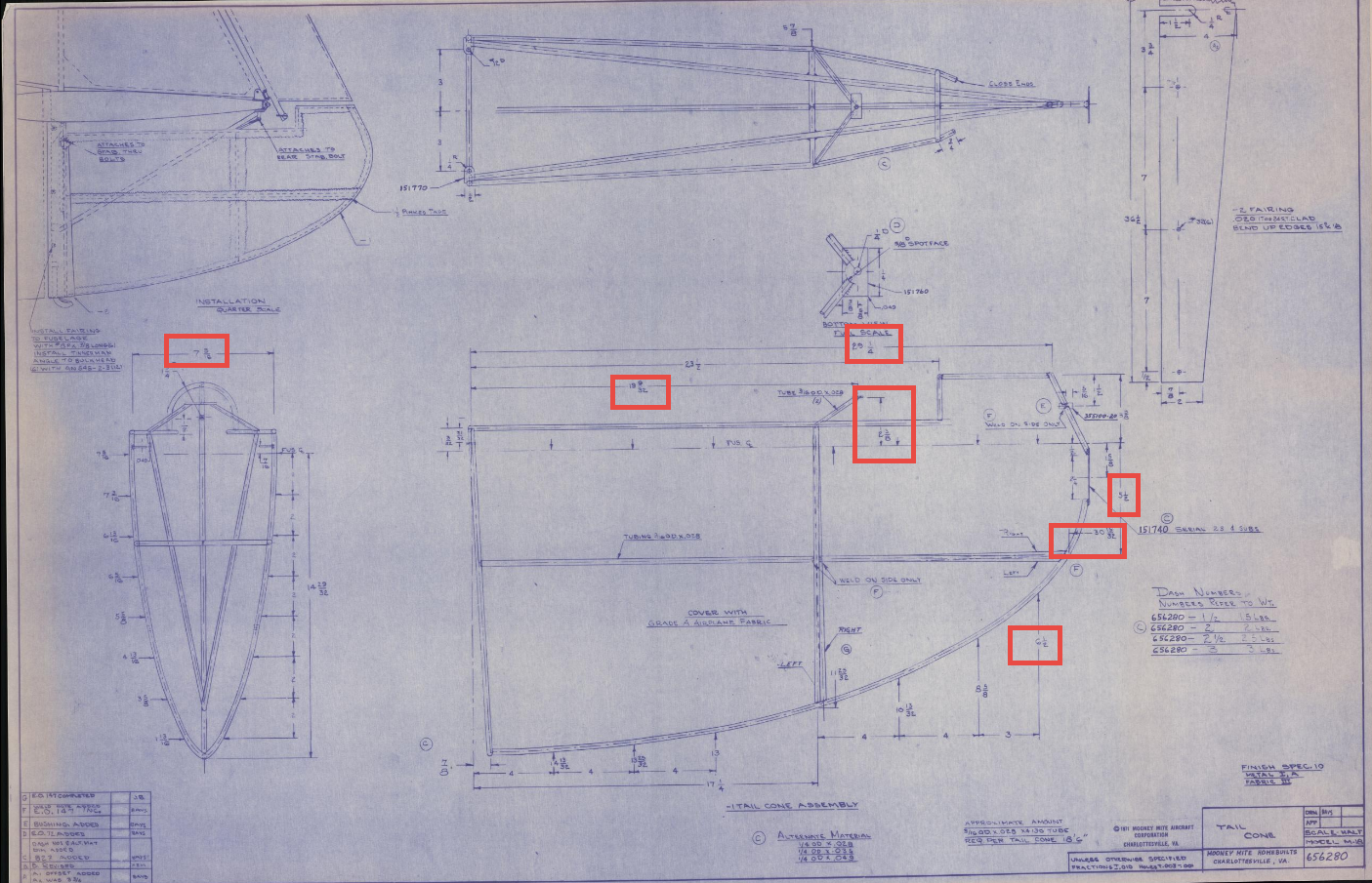
For reference, the dimensions shown on the end view (left) are on the vertical plane, not on the inclined plane for that section of tubing. I have been forced to compromise, which I rarely do, to get this thing to fit.
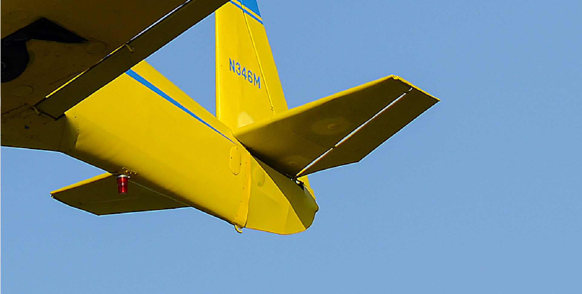
What I don’t understand is why they made such an effort to design a conical fuselage with beautifully shaped laminar flow wings, and even crafted a finely tuned, contoured cowling, only to attach this poorly designed piece to the tail end of the fuselage. What were they thinking?
It is puzzling that the fixing points for this component are also used for the main fixing points of the vertical and horizontal stabilisers. To remove just this part in order to access the inner components or to repair it will also necessitate the removal of the stabilisers. Why not have separate fitting points for easier removal and maintenance? Plus, it looks terrible!
Rant over, the model is now available for a small price of £38.95. This includes a 3D DWG and 3D IGES surfaced model along with the 2D drawings, Parts and Maintenance manual and fully editable Excel spreadsheets. A scaled RC version would make a great model. All the ribs and fuselage bulkheads are also included in this model.
PayPal is the preferred payment method, and download links will be sent to the recipient once payment is received. [PAYPAL LINK]… please include a contact email.
