Fastener Library Update: AN/MS Standards

Fastener Library Update: AN/MS Standards (Updated Jan 2024)

Over the years I have been further developing my AN (Army/Navy) or MS (Military Standard) parts library and only this morning did I eventually get around to uploading all the new files.

This is the list of Standard Fastener Parts now currently in the library…over 300 parts.

I have decided to make these files available as the original Inventor iParts. I was getting requests for different conversions to STP, Parasolid etc, and also at different scales…doing all that on request takes a lot of time. Don’t be put off by the fact that they are Inventor files as Inventor is readily available as a 30-day trial product which gives you several options for working with these parts. You can even install a Read Only version of Inventor

It is really simple to work with these files…let me show you. For a start, an iPart is actually a normal IPT part file inclusive of a table of parameters so you can generate multiple variations of the part in one file.

Part Conversion: I would assume that many people who don’t use Inventor will wish to convert to a file format more suited to their application.

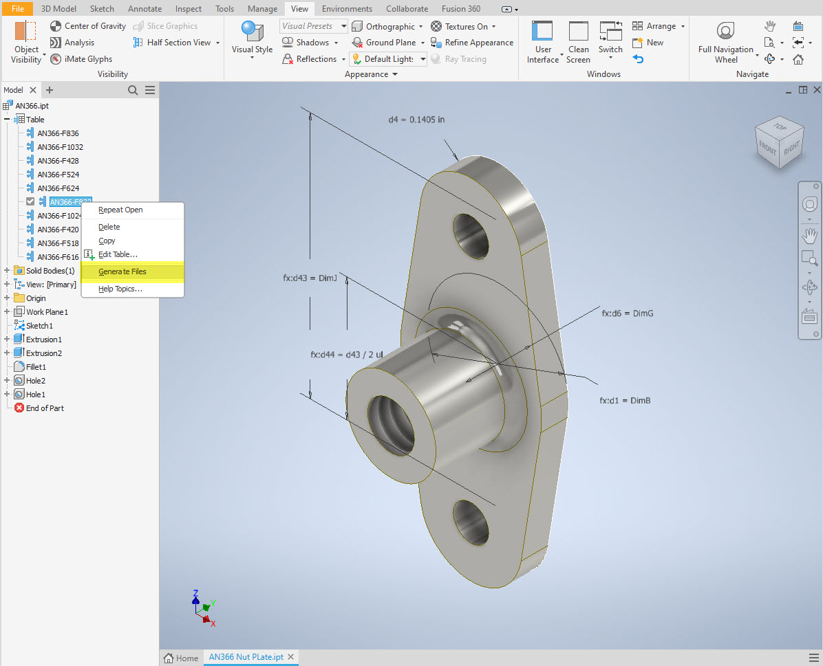
You can tell you have an iPart when the icon next to the part name in the model browser is shown as a table. To convert the file you simply expand the table folder; select the part or multiple parts and select generate files which will create a single IPT part file for each variant. This is placed in a subfolder named the same as the iPart filename. From there you can open this part file and Export whatever model format you want. Alternatively, if you would like to build your own version in a different CAD system it is useful to use the underlying sketch which can be Exported from this model; as shown in the second image which you can link separately to the Excel spreadsheet.

Table Editing: As I mentioned the part has an internal parameters table a bit like the format used by Excel which is fully editable. For the majority of the Library Parts, I also include the Excel table as a separate file.

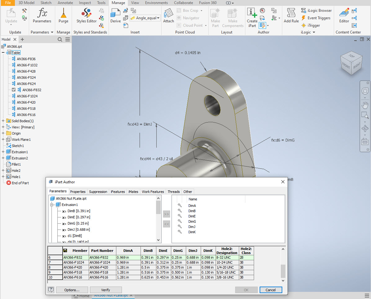
Accessing the Table is as simple as right-clicking on the “Table” text and selecting what editing option you want…either “Edit Table” (which opens the part table itself) or “Edit via Spreadsheet” which will open this same table in Excel. When you save the table in Excel it will revert to the Cad Part file and update the model with any changes. Making changes is much easier in Excel where you can add new variants of the part or amend existing ones. The dimensions are all in inches but if you bring this part into an mm metric part it will automatically adapt the inch dimensions to mm…so you can be assured that the part will be correct regardless of which units you use.

These part libraries include the most commonly used sizes so you can add to this as you desire. A copy of the original specifications is also included for reference. If you are looking for Aviation-related specifications then check out this free site: http://everyspec.com/library.php.

This library is included in all the CAD/Ordinate datasets and is now also available as a separate package. See this page for more details: https://hughtechnotes.com/resources/

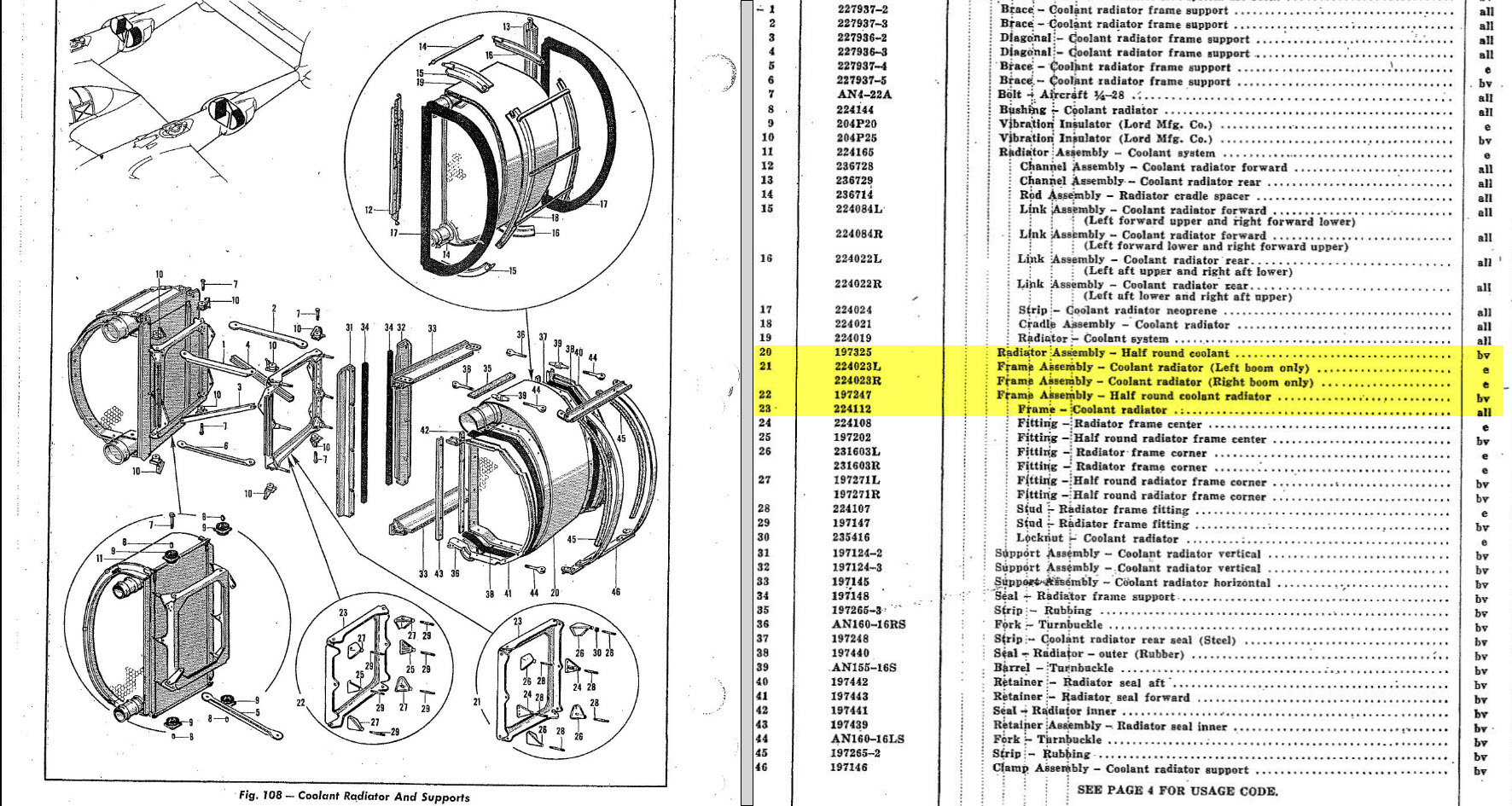
Manufacturers Standard Drawings:

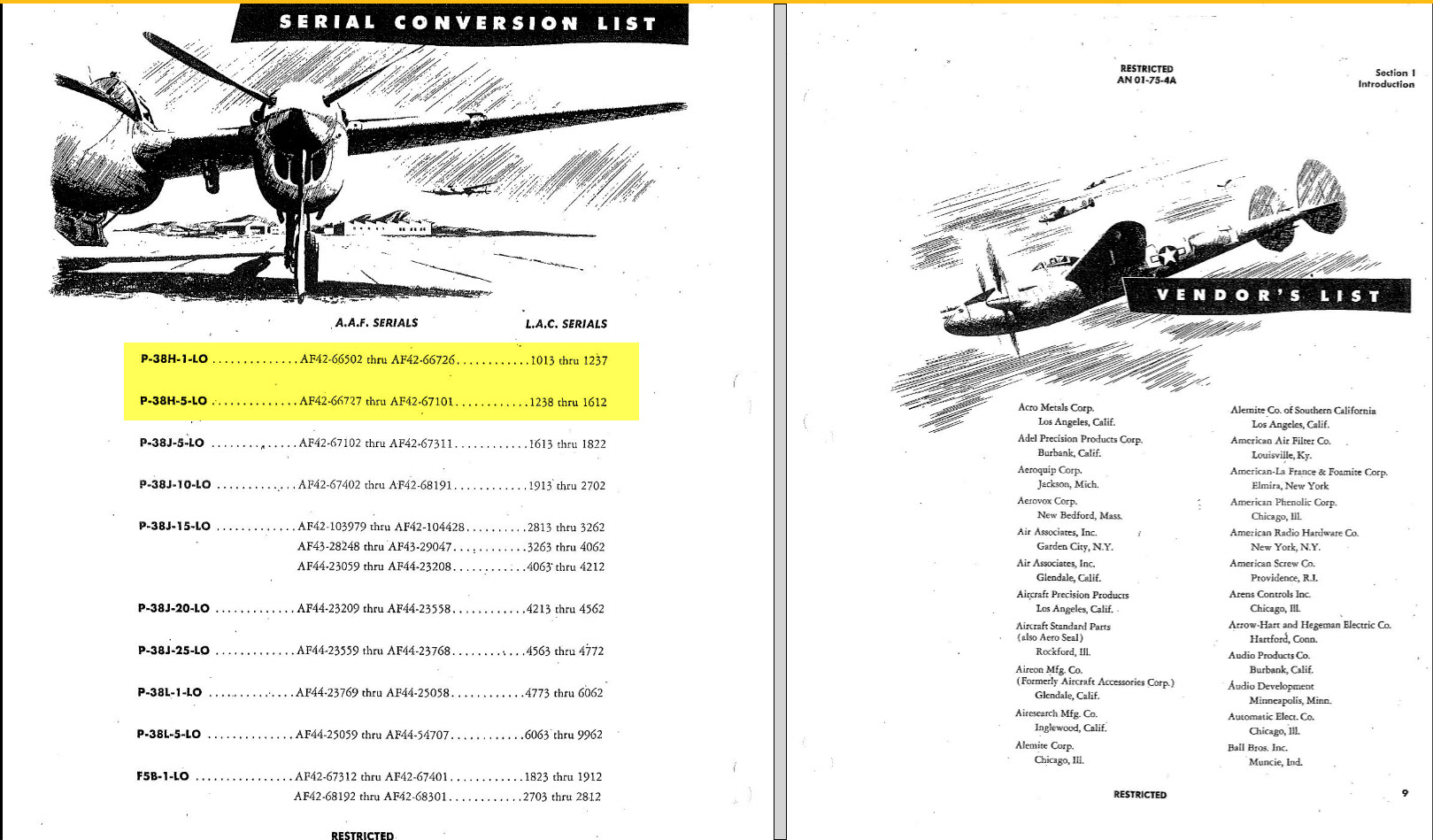
Included in the many blueprint archives are manufacturers’ Standard drawings, some of which are commonly shared specifications between various aircraft by the same manufacturer. I have a spreadsheet listing those standards for both Grumman and North American Aviation. This is available free at this link:

Manufacturers Standards (NAA and Grumman)

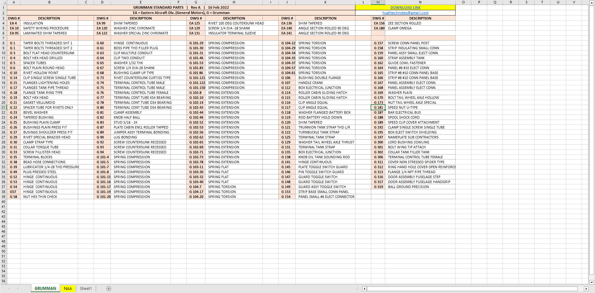
In the top right-hand corner of each worksheet is a link to a separate download area where all those standard drawing files are stored. As usual, the spreadsheet is fully editable so you can add to the data record as you find more information. I am sure you will find this is a beneficial resource by having all these important standards in one location. If you find these useful please consider a small donation to help support my work.

Technote: 3d Modeling to Clarify Assemblies

Technote: 3d Modeling to Clarify Assemblies

Interspersed throughout this blog are many examples of Technotes describing techniques and problem-solving primarily for 3d CAD modeling. Many of the part examples shown are actually created to address another major issue with Assemblies.

It is not uncommon for the assembly drawings to be either unclear or simply void of key information that would help establish relationships between sub-assemblies or parts. In many examples, it is simply that the reproduction of the microfilm prints is not sufficiently clear to comprehend what is going on, otherwise the omission of basic dimensional relationships.

For the P-51 Mustang, I fully developed the rear Landing Gear mechanisms to clarify what the heck was going on as the NAA Assembly drawings details were obscured.

It is too often the case that general assembly drawings tend to be nothing more than an illustrated parts list with few key dimensions that define locations or relationships between the individual parts. This is also true for many of the sub-assemblies. For the P-51 Tailwheel sub-assemblies, I also developed 2D detail drawings showing key dimensions and parts lists. Ideally, I would have developed presentation drawings showing the exploded views of each of these assemblies to provide further clarification…perhaps a project for the future.

In the case of the P-38 Lightning, I have developed the Landing Gear assemblies to check the ordinate dimensions… which by the way are good. I now have the Coolant Radiator assembly which was again developed to check ordinate data but also for the same reasons as I did the models for the P-51 Tailwheel.

Typically the general assembly pictorially shows the sub-assemblies without any key dimensional information to define the location or part relationships and similarly, the sub-assembly for the clamp is not that much better. This is important stuff as occasionally they are the only reference material we have to help define ordinate data that is missing from the archive blueprints.

The Coolant Radiator is compromised by wrong dimensions as well…the top clamp cover, for example, had dimensions for the connection to the rod with the part drawing showing conflicting locations for different views of the same part.

The problem here is the connecting bracket item 224045 cannot possibly be 1″ from the edge of the cover plate whilst the overall dimension of 6 7/16″ prevails. I initially had located that bracket at 1 inch which seemed to be correct at the time because it fitted the part profile but when I introduced this into the assembly drawing it would not correctly align with the radiator. However, when I revised this using the 6 7/16 inch dimension it worked. That connecting part also caused more problems because the face of the part is machined 1/64″ which is not taken into account when positioning the part in the assembly.

Accumulatively this resulted in the overall width of the clamp assembly being smaller than it should be. This only came to light when I modeled the 234183 almost inconspicuous part as the stated dimension of 9.25″ did not fit with my initial layout..my first thought was this may just be an oversight but when I tried to align the main support frame (in gray) it did not align correctly. I went through everything and realized that the machined face of the corner parts connecting to the rod as shown may not have been taken into account and when removed the alignment was better and the 9.25-inch dimension on the strap was now correct. I am convinced that there should be spacers/washers between those connecting parts but this is not apparent on the assembly drawings. There remains a small discrepancy of 0.8mm which I am unable to account for….as this mainly relates to a clamp mechanism that will be compressed on assembly it was probably not deemed important but when you are trying to establish baseline dimensions it is actually very important.

The Part catalogs generally are your first port of call when developing these assemblies but they do not contain the key dimensions you need so these 3d CAD models are essential to achieve clarity. Incidentally, while we are talking about part catalogs it is important to understand what parts belong to which version of the aircraft. For the P-38 Lightning, the first few pages list the version and serial numbers which in turn are listed elsewhere where a Usage code is assigned. In this case the “e” is essentially the P-38H and the “bv” is the P-38J. The P-38 Part catalogs tend to show the version variations on one page; which can be really daunting; whereas others may show the version differences on separate pages…so you have to be attentive.

As I mentioned at the beginning of this article the main purpose of these assembly models is to achieve clarity and to check dimensional relationships. I think this is very important stuff that would certainly benefit from exploded views in conjunction with clear assembly 2d drawings.

As usual, get in touch if you can help support my work. hughtechnotes@gmail.com

P-38 Lightning: Ord/Dimensions Study Complete

P-38 Lightning: Ord/Dimensions Study Complete:

The P-38 Lightning Ordinate/Dimension study is now finished after 7 long months. Initially, I had planned on doing this study in 3 months; working night and day; but alas due to the complexity of this aircraft this drifted into 7 months.

All areas of the aircraft have been studied, and modeled with all known, and henceforth many previously unknown dimensions collected and recorded in a comprehensive spreadsheet.

All bulkhead and rib profiles are generated for the wings, ailerons, elevators, horizontal and vertical stabilizers, rudder, fore and aft booms, fuselage, cockpit, and flaps. The latter was a challenge as the Lockheed drawings were unclear about the relationship of the flaps to the wings…however, after some research, I was able to resolve this issue to determine the exact positions of the Wing and Center Section flaps. The flap details are fully dimensioned now on 2d Acad drawings…that was the last hurdle.

Further to the Ordinate study I also have full 3d Cad models for the Nose and main Landing Gear Assemblies.

For further details get in touch: hughtechnotes@gmail.com