Technote: P-38 Lightning Wing Tip Development:
Developing this wing tip turned out to be more complex than I originally thought it would be. Because the model required a few interesting techniques I figured it is worthy of a quick technote that hopefully will assist others.


First, off the bat, you will probably have noticed the center partition which came about as a consequence of the development process. I will try to explain how this transpired…read on for more details.


What we have is essentially one main rib profile at Station 289 and 2 others towards the tip which you would normally just loft to achieve the finished surface assuming that the required outline guide rails were included in the initial data set. Actually in this case we didn’t have those curved outlines as a 3d profile only a 2d outline on the plan view. Even with the guide rails in place just lofting the full rib profiles did not work due to the continuity of the rails in a circular manner that prevented a successful loft.
By the way, the circular guide rails at “A” and “B” were generated as intersection curves using a side profile (top right in the background) and the plan profile to derive the resulting intersection lines. I initially wanted to extrude the 2d plan profile and build a 3d curve on the face of the surface but I was unable to apply a tangent constraint to align with the Leading and Trailing edges…so my only option was a 3d intersection curve.
Realizing that a full rib profile loft was not achievable I decided to fill each rib profile with a patch surface and then split the surface at the main beam intersection, which incidentally is perpendicular to the ribs. So this gave me a patchwork of surfaces fore and aft that I used as surface profiles and lofted each section as shown using the guide rails at “A” and “B” and the center rail at “C”…this created the partition I mentioned in the beginning.

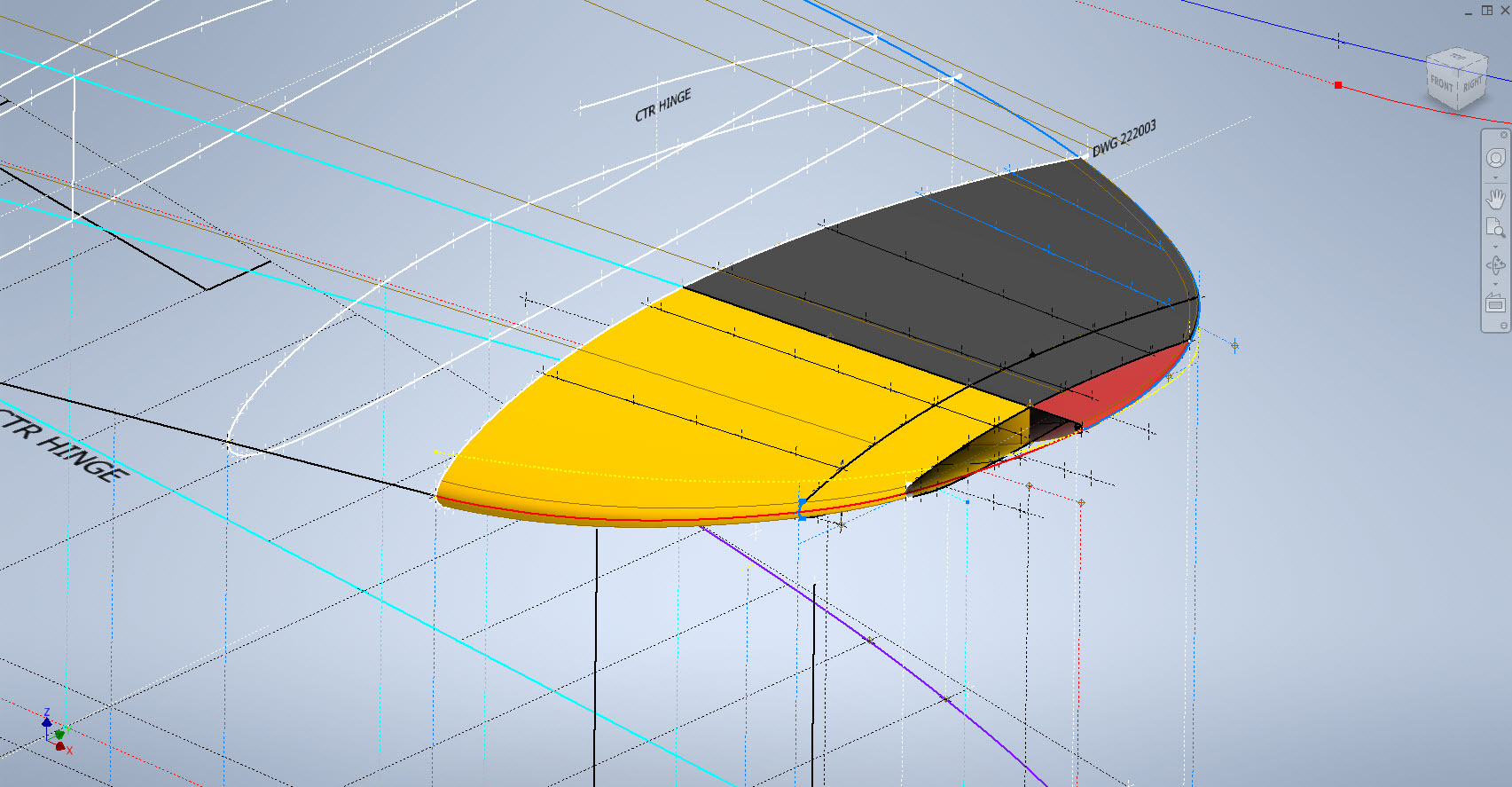
Once the main fore and aft sections were modeled I then proceeded with the extreme tip which was simply a case of again adding a surface patch to the small projecting profile in the center and lofting the surfaces separately as before. Occasionally when you have problems with lofting it often helps to break it down into more manageable chunks.
Accuracy is extremely important to ensure a good surface finish with no small deviations or folds. So I checked the coordinates of each profile mathematically and adjusted the dimensions accordingly for the top surface.
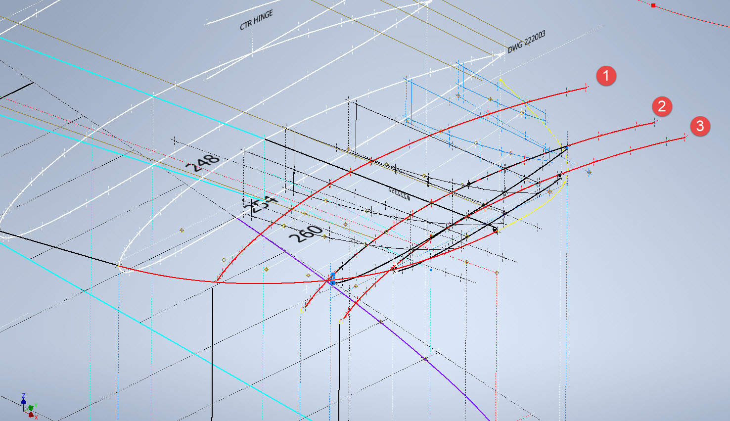
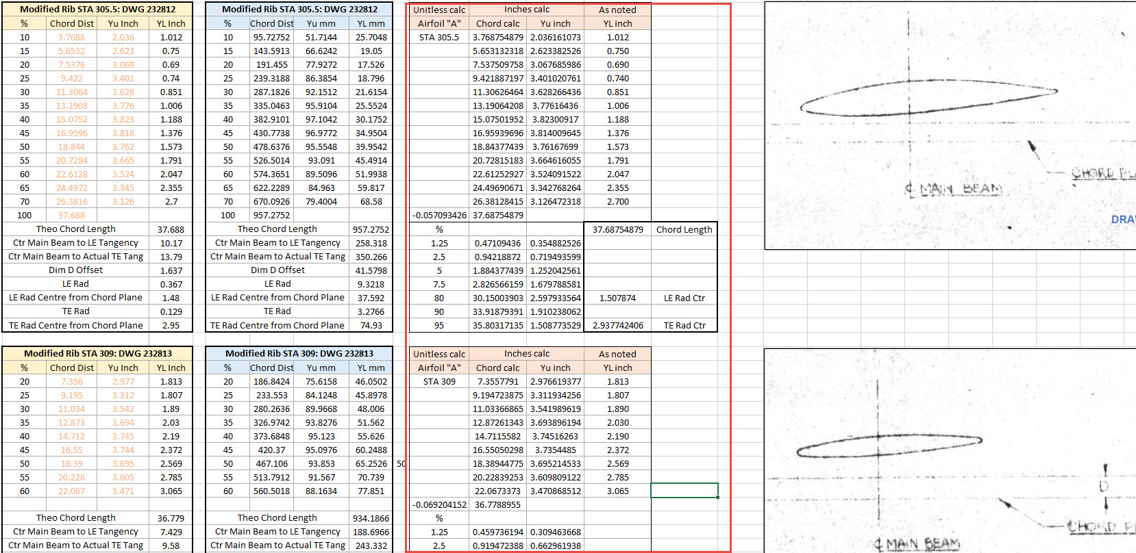
The rib profile at 1,2 and 3 was adjusted to the new coordinates for the top line only but making sure that the LE and TE were tangential to the mathematically generated curves shown in red. These end ribs are actually modified profiles according to the tabulated information on the Lockheed drawings…apparently, the profile at the wing tips is based on a NACA 4412 airfoil but when I generated a 4412 it did not match…I am not sure why but it is something that warrants further research. As I did not have the mathematical formulas or guidance on hand to check the lower profiles I accepted what information was contained in the tables…mind you I could have generated a line equation from this information in Excel. Incidentally, all the wing ribs were checked mathematically with the resulting dimensions used to generate the profiles throughout.
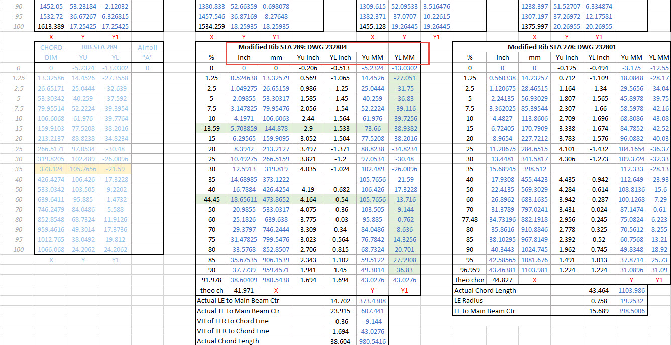

The first image shows a sample of the modified values at Rib station 289, highlighted in green alongside the normal profile on the left. The second image shows the explanation of how the main wing rib profiles were generated. All this information is included in the CAD/ordinate dataset. Also on the second image, you can see a typical rib profile extracted from the Lockheed drawings which shows the 0% chord is actually set back from the Leading Edge, which is most unusual. This created a few problems because now I had to determine from the CAD model the Actual Leading Edge before I could define the curved guide rails for generating the wing tip lofts.
This all may seem overkill and a lot more work than one would expect just to build a wing tip but the Inventor Loft command requires absolute precision when lofting with guide rails so it pays dividends to mathematically check everything where possible to ensure successful lofting. I shall update the CAD/Ordinate dataset over the next few days to include this new data.
.
.
.
