Grumman F4F Wildcat: Aileron:
Having made good progress on the ordinate set for the Grumman F4F/FM2 I decided to put the spreadsheets to one side and do some modeling to verify the dataset. Normally this would not be required to such an extent but I needed to do this to check the relationship between the components and aircraft datums.


I was spoiled with the P-39 project where virtually every component has reference dimensions to the ship center line or thrust lines so positioning was a breeze. However, the F4F drawings sadly lack this reference information on many of the key drawings so developing the 3d cad model is the only sure way to ascertain this data.

The above model is the left-hand Aileron modeled in Inventor and rendered in Keyshot. Keyshot is a very good renderer, even for a novice like myself; in which you can generate acceptable renderings very quickly. The real-time rendering is very good and will continue without glitches even on a modestly specced system (unlike some of the alternative products). The user interface is logically set out with a good library of materials and textures. I would highly recommend this product.
Getting back on subject; the Aileron ordinates took a long time to complete for various reasons; requiring constant checking and verifying. Once this was done, the modeling was reasonably straightforward except for the small trimming tab. The drawing dimensions are slightly out, so I extracted the neighboring rib profiles to create the template for a finished model.
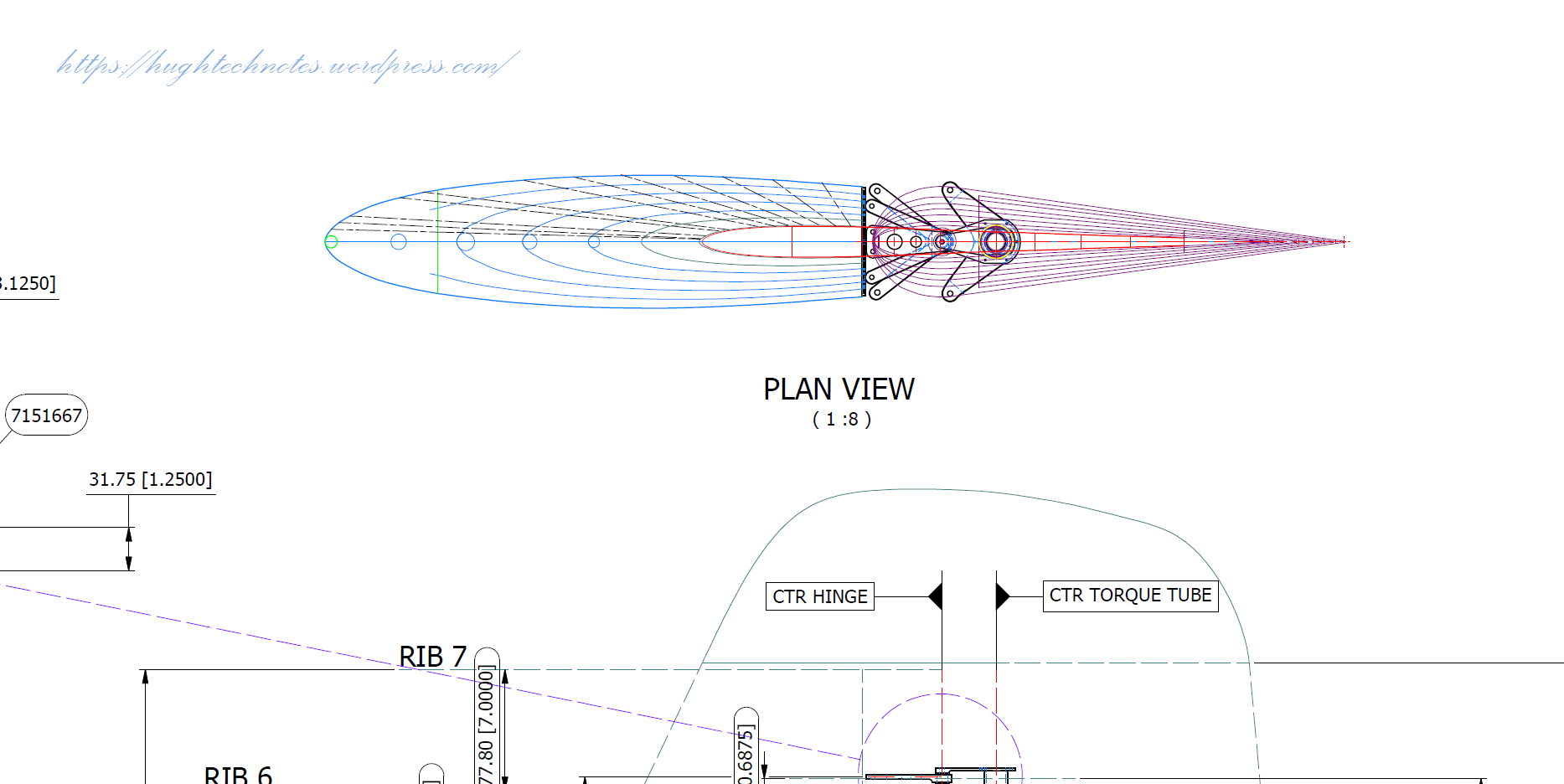
I also decided to create a few scrap drawing views as a matter of record that will be useful when I eventually move onto modeling the wings themselves.

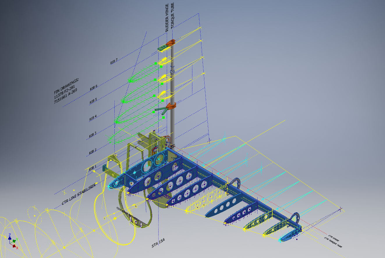
For reference; the following image shows the Ailerons attached to the wing assembly. Hinge positions checked and verified with hinge brackets (orange) fitted achieving a planar variation of less than 0.04mm.

There are still a few items required to complete this model but this is not a priority for me right now. My next objective is to develop the ordinates and perhaps some modeling for the vertical and horizontal stabilizers.
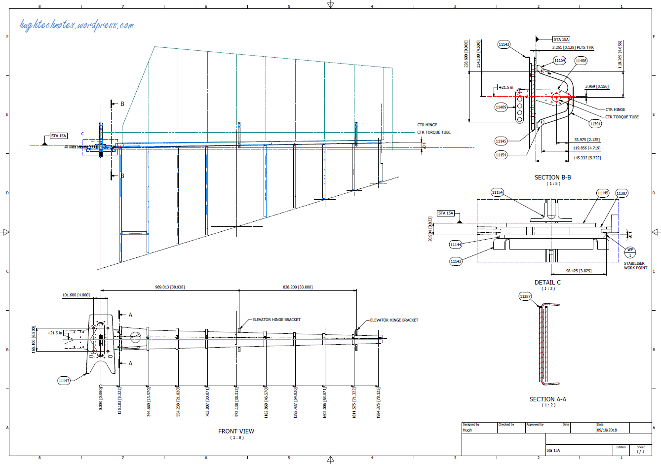
Horizontal Stabiliser & Elevator:

Tail Fin & Rudder:

Fuselage Frame 3:

If you are interested in obtaining my research data for this aircraft then please send me an email. At the moment this is an unfinished project but the available drawings (12) are fully dimensioned which will help you with establishing correct datums and station frame associations along with a few spreadsheets. HughTechnotes@gmail.com

