Technote: P-47 Canopy Contour Lines

Technote: P-47 Canopy Contour Lines:

In a previous post, I discussed a minor discrepancy at the intersection of the canopy contour lines and the fuselage contours. This discrepancy is quite small, measuring around 0.3 mm, which is generally considered an acceptable tolerance. The purpose of these CAD/Ordinate studies is to provide the most accurate dimensional record for the various aircraft currently available, so it is crucial to ensure that these measurements are correct. However we must first understand design intent and check that the canopy contour ordinates are designed to match the fuselage contours.

Depending on the aircraft manufacturer, the canopy contour lines may not align exactly with the fuselage because the canopy surface is typically offset from the fuselage surface, which is reflected in the information provided. For the P-47 you can see the ordinate points are an exact match with coincident curves from the fuselage surface therefore the tangent line is actually defined by the intersection between the canopy contours and the fuselage contours.

Initially, when I started this study, I profiled all the ordinate points for the canopy and compared this with the fuselage surface, revealing a minor discrepancy. The thing is we don’t have to fully connect all the coordinate points for the canopy, just the points above the intersection line.

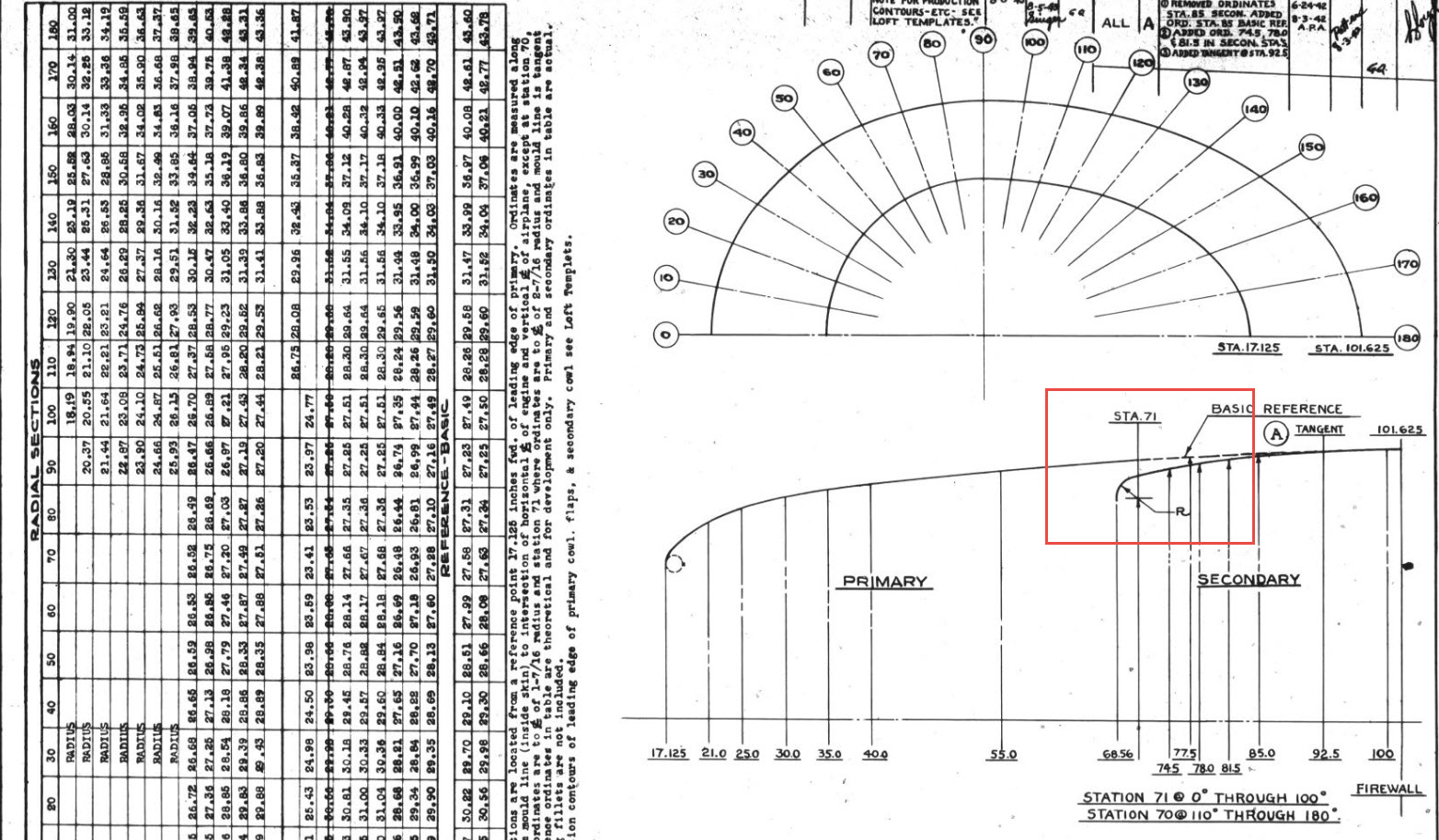
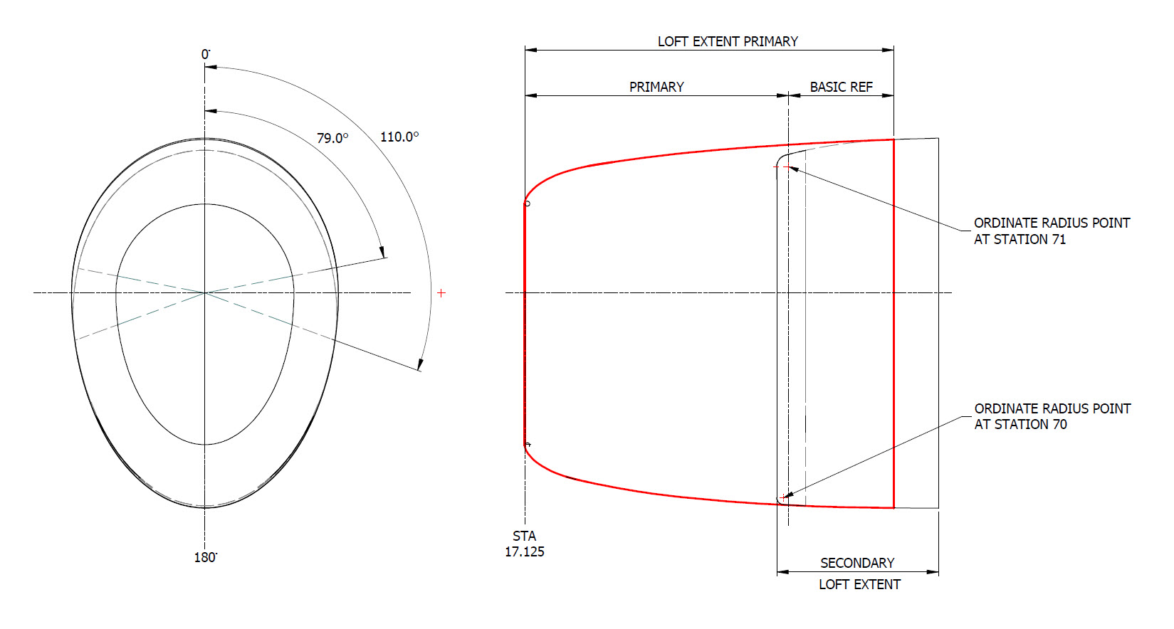
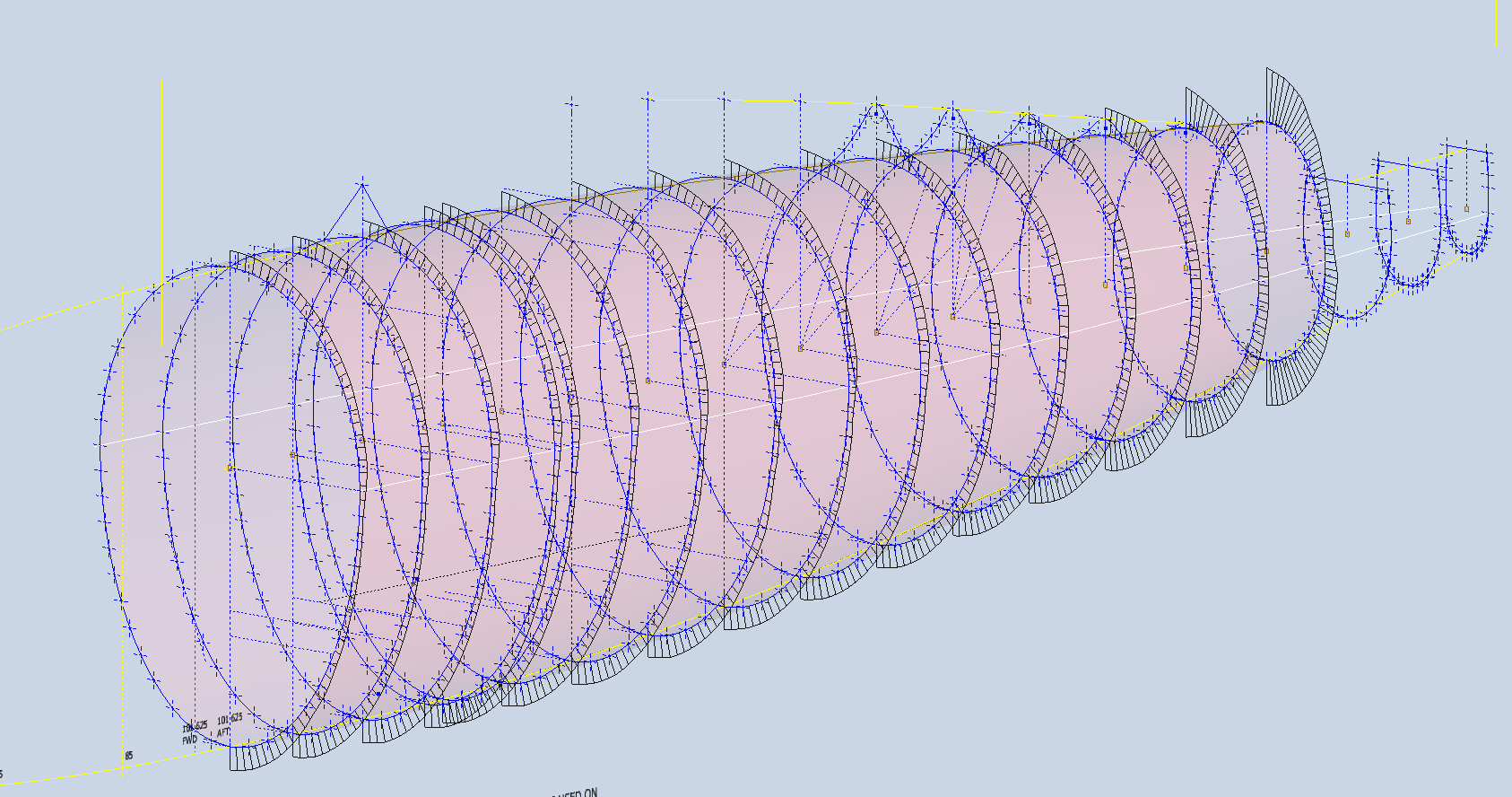
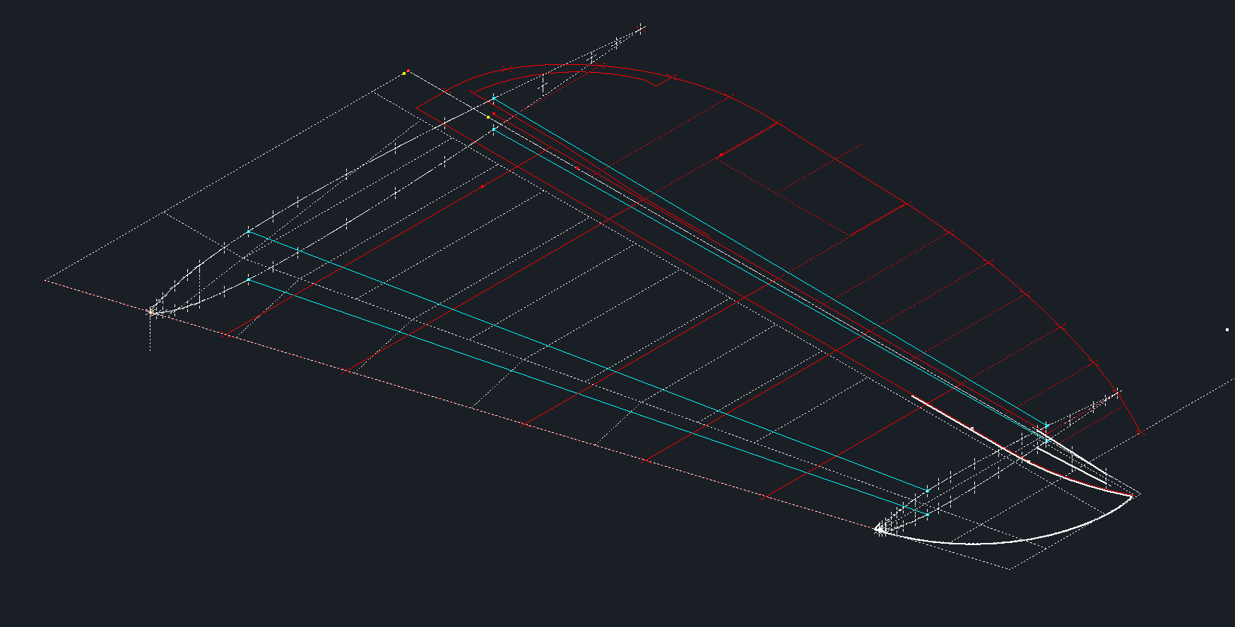
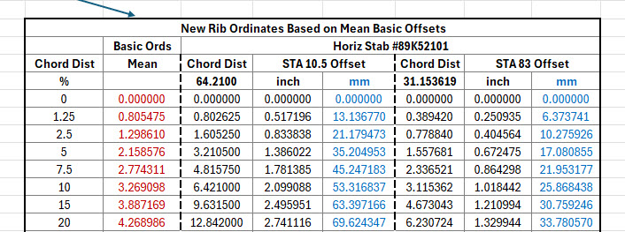
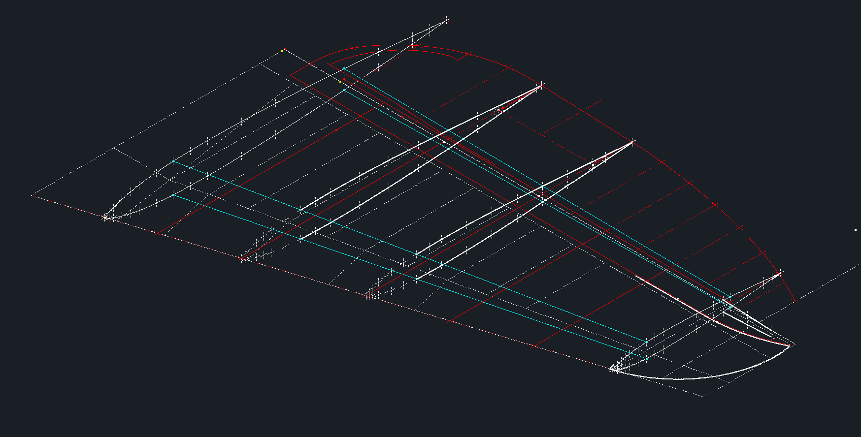
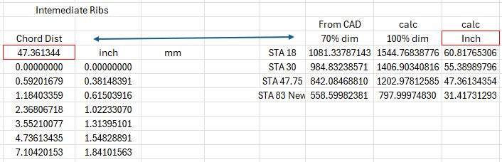
First, we need to define the actual definition of this intersection on the fuselage surface which will be transposed to the canopy model. We take the vertical dimensions from the fuselage centre as defined on the canopy ordinate drawing #89F11456 and create a sketch which will be lofted to split the fuselage surface. On the second image above you will notice a number of prominent points on the upper curve profiles. These ordinates are not shown on the early P-47D drawing but are shown the on the later P-47D and P-47N ordinate layouts.

Initially, I opted for a tangent spline curve to complete the main circular profile of the fuselage bulkheads as per the ordinate drawing thinking that the relevance to the finished profile was nonessential. However when I compared the first run of the canopy and fuselage alignment studies I found that it was necessary to include those additional ordinates which are now included in the spreadsheet record.

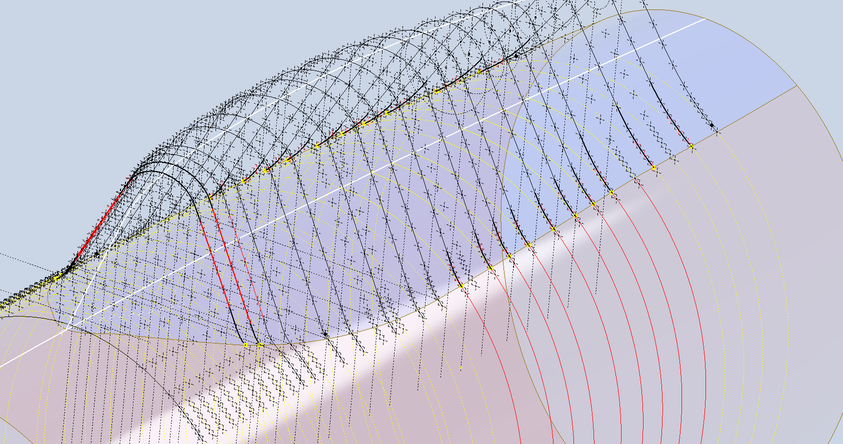
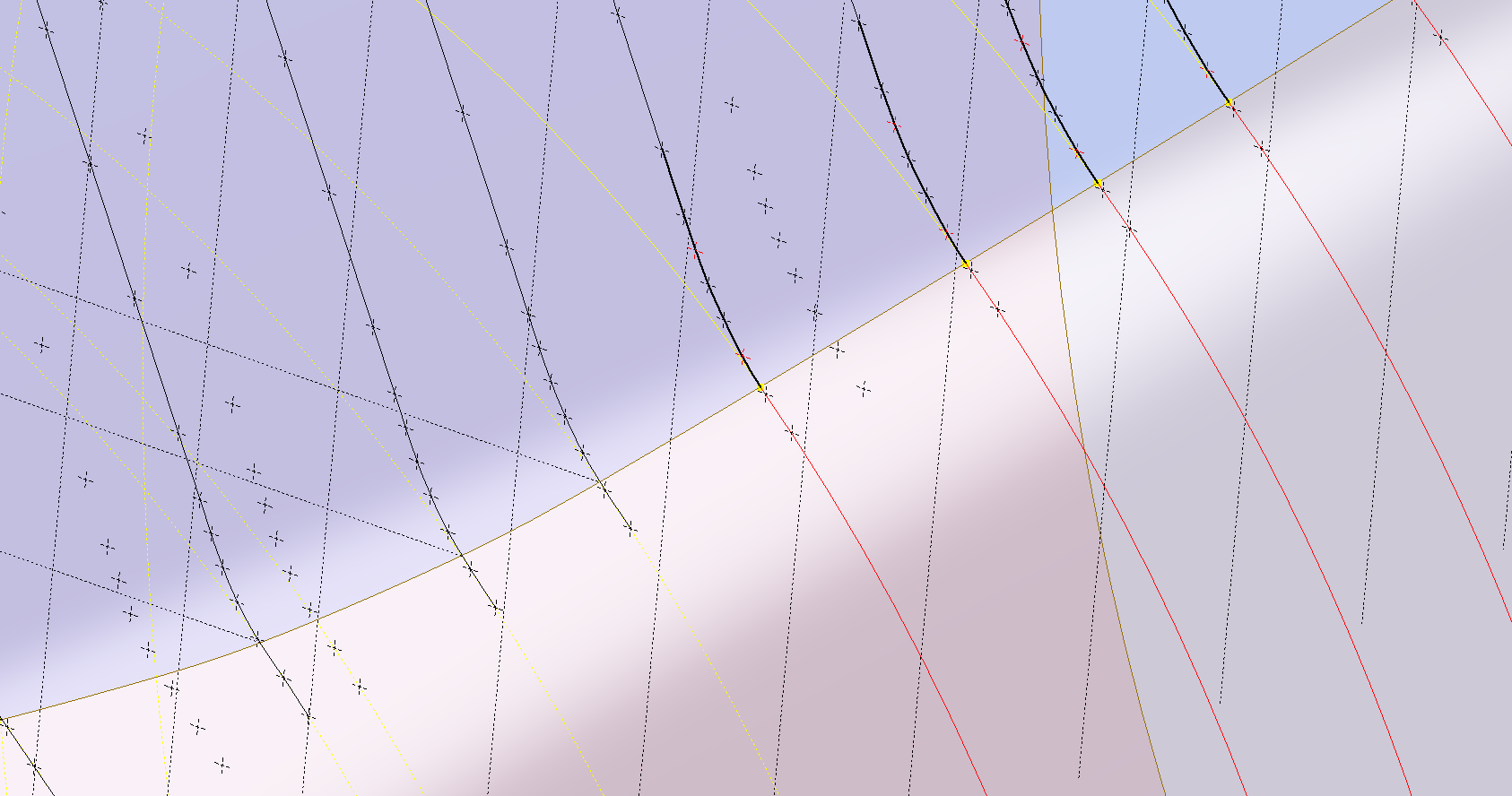
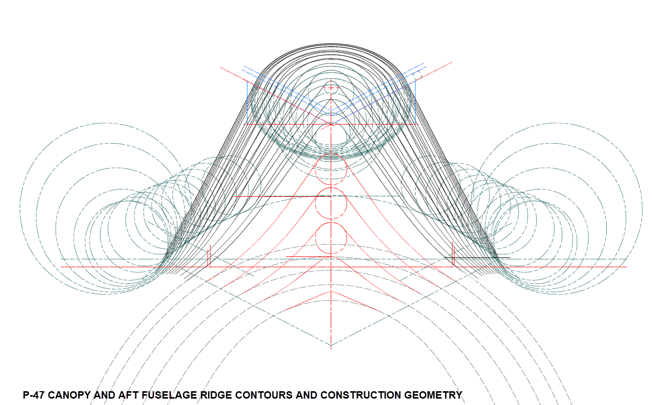
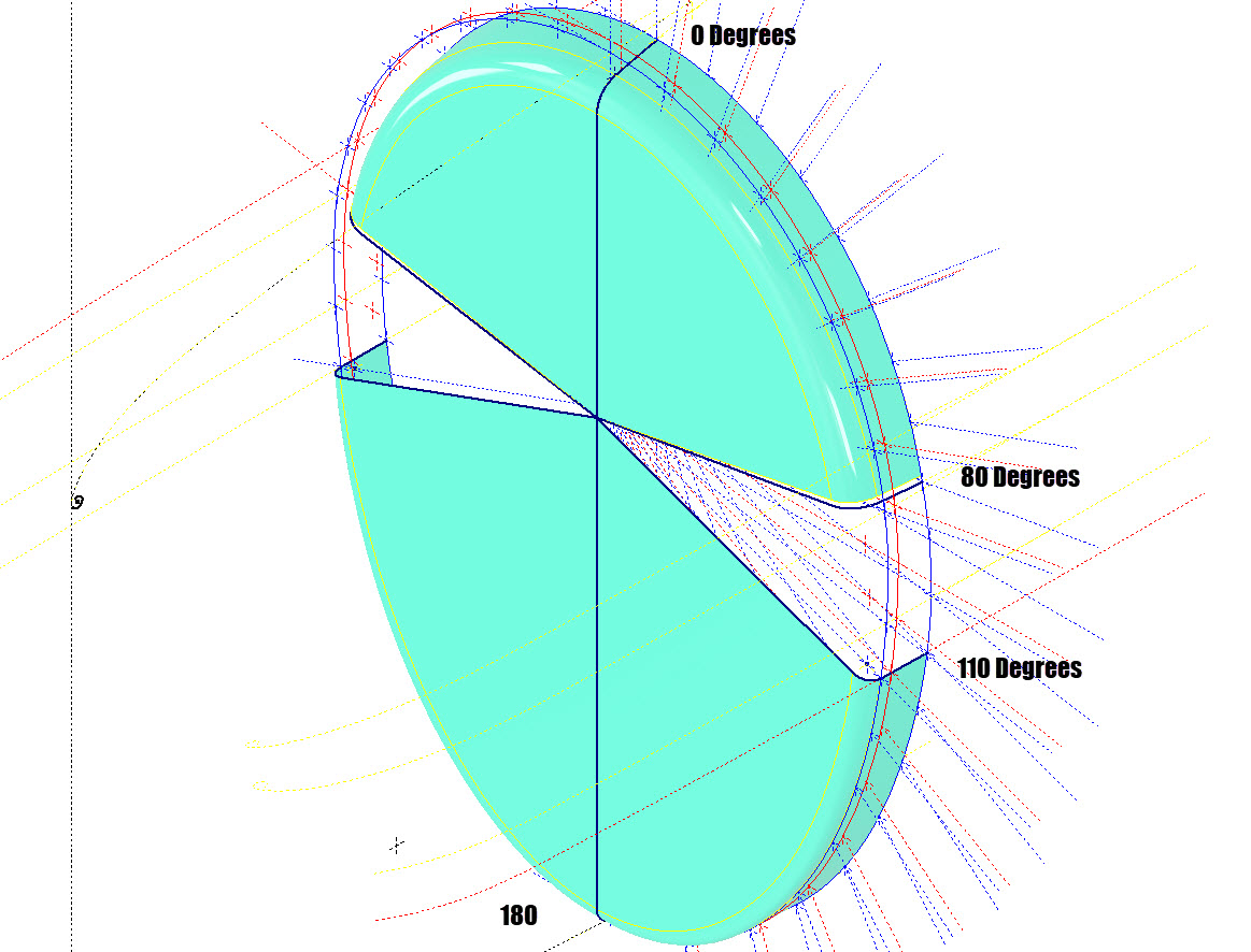
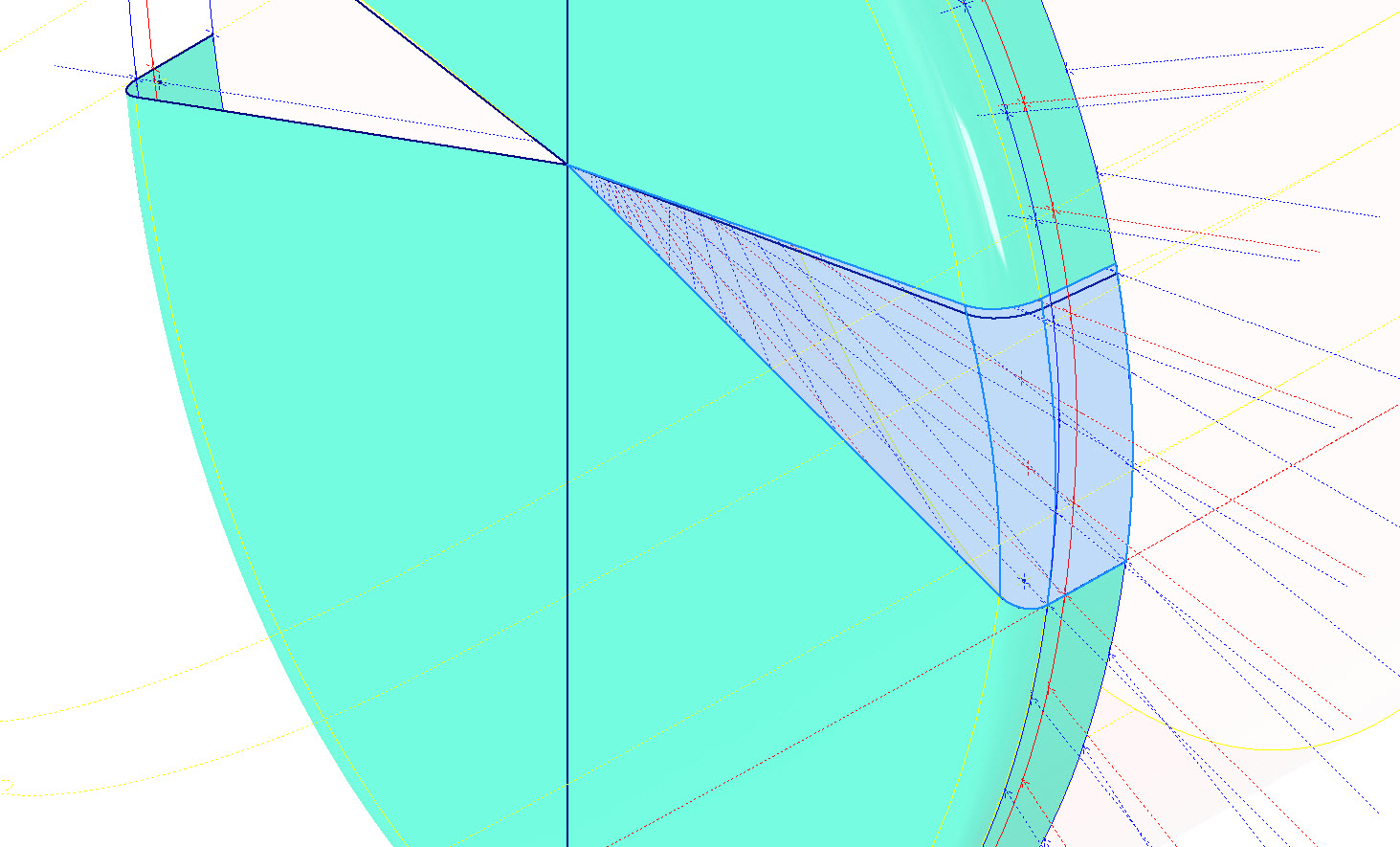
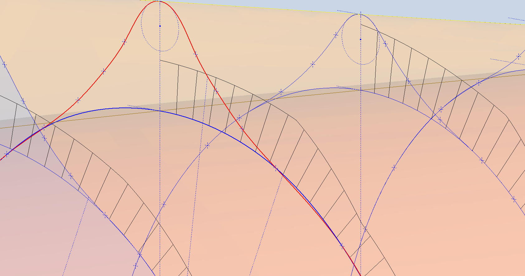
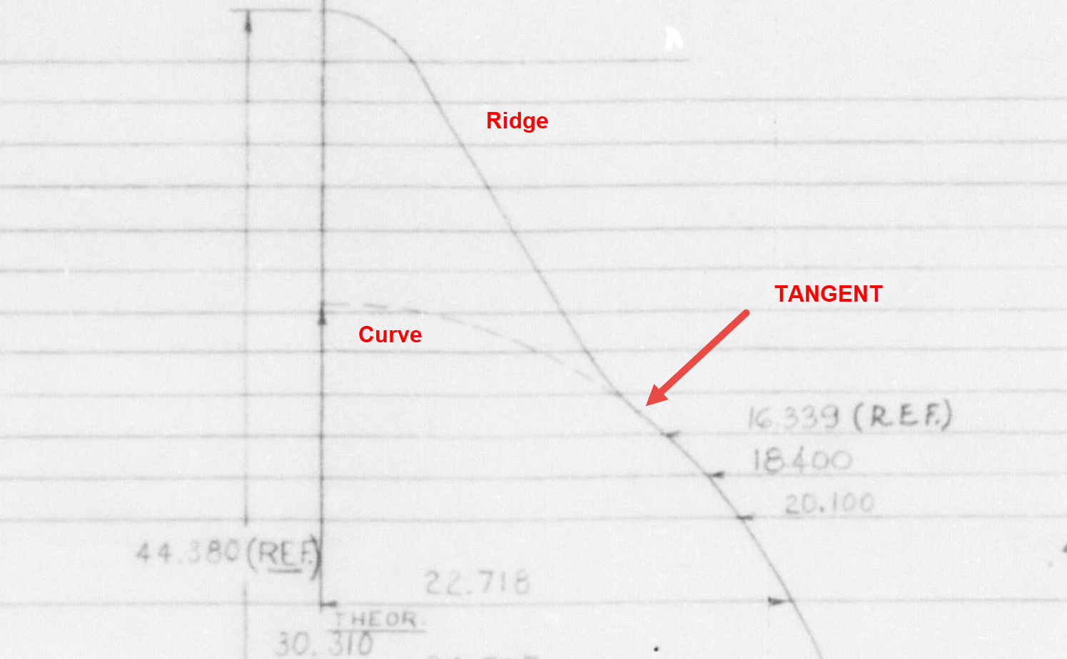
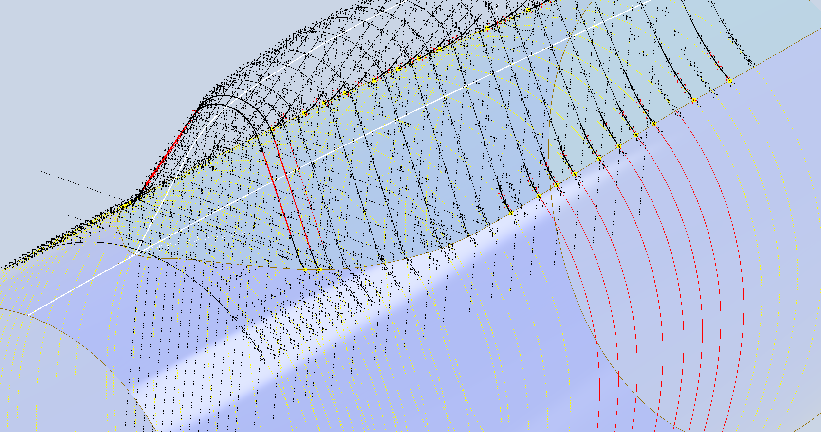
These images show I have opted to correct the minor discrepancy by only profiling the canopy to the actual intersection line. I should note the Canopy and Fuselage are separate CAD models which means I can derive the surface from the fuselage model and manipulate it as required in the canopy model without affecting the original. For each canopy station, I projected a section thru the fuselage surface which gave me a spline to which I could add a tangent constraint when profiling the canopy lines. The images show the initial interpretation of the canopy profiles and the corrected profile in red (construction geometry omitted for clarity).

Tech Tip: if we had instead derived the station sketches from the fuselage model and then projected this in the canopy frame sketches as an outline we would not be able to add a tangent constraint. This is a limitation with Autodesk Inventor when working with splines and the workaround is to project a surface cut section as I have done above.

For each canopy station, I am only sketching the ordinates down to the intersection line with the fuselage and adding a tangent constraint to the projected fuselage profile curve. Because we split the fuselage surface we will have a point at the split that we can use in the profiling of the canopy frames.

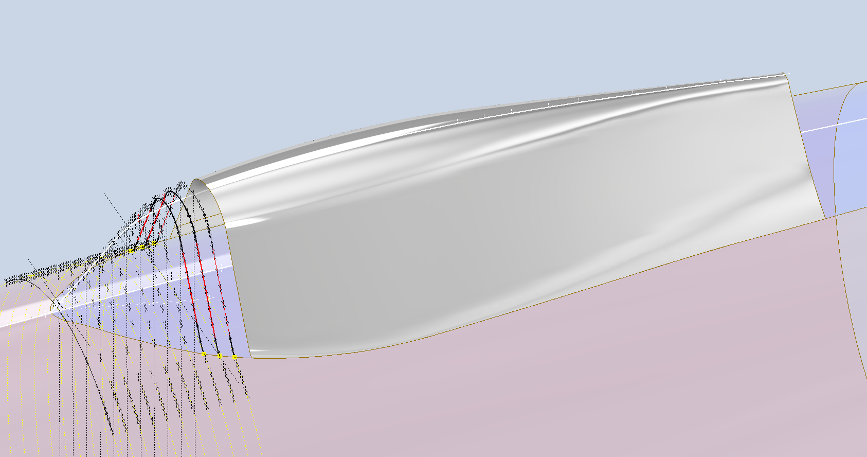
The actual skirt for the canopy obviously overlaps the fuselage surface and therefore we will have to define the edge relative to the tangent intersection line. As mentioned before we can manipulate the fuselage surface that is derived in the canopy model which means we can trim that to suit without impacting the fuselage model.

The tricky bit is ensuring that the edge of the skirt is exactly the same dimension from any point along the intersection line and this is how I do that.

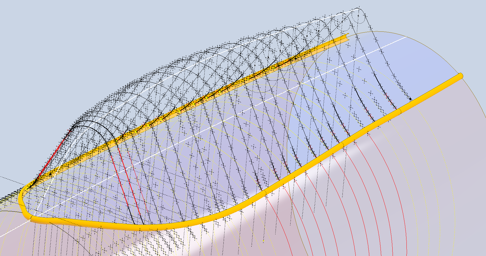
The first thing to do is create a work plane perpendicular to the intersection line and draw in a partial curve and then sweep this along the intersection line path. The reason for this being a partial curve and not a full circle is because there is a tight radius at the front edge of the canopy which may not be possible to traverse using the sweep command if this was full circle.

When this is done it is a simple exercise to trim the derived fuselage surface to obtain the skirt surface.

By creating a curved sketch and sweeping along a curved profile we ensure that at any point along this path, the distance to the resulting edge is exactly the same. A similar technique will be employed to develop the finished edge of the glass panel models.

I still have some work to do on the windscreen portion of the front canopy and then I will fully model the structural components.

Technote: P-47 Cowl Ordinates

Technote: P-47 Cowl Ordinates:

The Ordinates for the P-47 Cowl are listed on Republic Drawing #89P63300 for P-47B, C and D. They differ from the usual ordinate dimensions that usually comprise X and Y coordinates in that they are radial ordinates. Essentially dimensions along a radial axis that are subdivided in 10-degree increments from 0 degrees to 180 degrees.

The ordinates as usual are extrapolated to a spreadsheets where I have also converted the radial ordinates into X,Y coordinates should this be required. The highlighted dimensions are the points on the inside face of the cowl skin. The dimensions at Stations 70 and 71, bordered in red, are to the centre of the secondary cowl leading edge radius at each degree increment. To be precise this is actually the profile for the Preheater.

The edge radius at the top of the Preheater is 2 7/16″ at Station 71 and 1 7/16″ at Station 70. On the Republic blueprint the radius of 2 7/16″ is applicable from 0 degrees to 100 degrees, and the radius of 1 7/16 ” is applicable from 110 degrees to 180 degrees. In the CAD drawing above, I have noted 79-degree and 110-degree intervals, and there is a reason for this.

At some point along this Preheater front edge, there is a transition from the 2 7/16″ radius to the 1 7/16″ radius. The republic blueprint for Preheater #89P621101 details the profile section that is applicable at 90 and 100 degrees showing the top radius at 2 7/16″ however it also notes an option where the radius fairs from 79 degrees to 110 degrees instead of 100 degrees to 110 degrees.

Personally, I prefer the latter as it ensures a smoother surface continuity. As you can see in the following image of a recent P-47 restoration they appear to have opted for the former which displays a noticeable bump from the 100 to 110-degree transition. The second image is the CAD interpretation of 79 to 110 degrees which is much smoother.

I have modeled only the main portion of the Preheater body surface; there is a projected curved section forward of this which I will model separately and again a good reason for doing this*.

If we look at the CAD development of the Preheater surface model you can see I have developed the top profile with an ordinate radius of 2 7/16″ to the 80 degree increment and the lower section ordinate radius 1 7/16″ from 110 to 180-degree increment. However, when you loft the 2 profiles you can see the default curvature transition is not continuous…what we want is for the curved section to have smooth continuity throughout the transition.

I should note that the surface was developed to the 80-degree increment and then trimmed back to 79 degrees; I already had the construction sketches in the model…just saves some work.

Inventor like other CAD software will attempt to interpret the desired surface loft but it does not always achieve the desired result. This is easily corrected by selecting transition points within the Loft dialog which will enable a smoother transition.

Going back to my earlier comment on the projected curved section*; as per comments above; the CAD-interpreted surface may not produce the desired result with more complex geometry. So often the best way of doing this is to model that section separately ensuring finer control over the finished surface.

CAD Tip: The vertical face of this developed surface is flat, occasionally when lofting, sweeps or even applying a surface patch it is always a good idea to check the finished surface is actually flat and planar where expected. The way to check that a surface is planar is to select the New Sketch option using the surface as a sketch plane…if the surface is planar it will allow a sketch.

P-47 Engine Mount:

On the Republic Drawing #89P62101 for the Engine Mount the intersection point of the top diagonal brace with the centre of the front ring is not clear.

On the Front View, we have either a dimension of 8.75″ (1) or an Angle of 58.5 degrees (2). To verify which is the correct set out for the top brace we turn to the elevation view. Here we have a cross brace intersecting the top diagonal at 20 21/32″ (4) and 16.592″ (3). Drawing in this intersection point in conjunction with the known datum at the extreme right we project the centre line of the brace to intersect with the front ring.

This projected point is within 0.017837600 mm of the point determined by the dimension 8.75″ (1) and 1.057782238 mm where the angled line (2) intersects with the ring centre. This verifies that the actual point of intersection is the dimension 8.75″.

P-47 Fuselage Curvature Analysis:

The following image shows the curvature analysis at each station of the fuselage. Only 4 rogue points were micro-adjusted to align correctly. What we are looking for here is not perfection but consistency. You will notice a small flattening of the side curves around the centre of the fuselage, which is fairly consistent throughout. The primary reason for doing this is to identify any points that will create a negative curvature or completely in the wrong position.

The next challenge is to identify the correct tangent points between the humped back ridge curves and the main fuselage. It may tempting to just profile a spline connecting all the points from the ridge curves and the main fuselage but this is likely to create small imperfections where the tight curves meet the main body profiles…so it is always best to do this separately.

In the first image above the red line is the best fit spline connecting all profile points and you can see how it dips below the curved profile from the blue main fuselage curve profile. From the Republic ordinate drawing it is clear the intent is for the ridge profile to be tangent at the point of intersection.

The finished profiles will look something like this…

P-47 Canopy and Grumman Goose Nacelle

P-47 Canopy and Grumman Goose Nacelle

The P-47 project has now incorporated the Canopy Basic Layout. This Basic Layout represents the surface derived from the table of ordinates, with dimensions that reflect the mold lines at the inner face of the skin. An allowance of 1/32″ is required to accurately represent the actual surface of the canopy glass. All ordinate points are provided in an Excel spreadsheet, as is customary.

Once the best-fit surface is determined, it undergoes a curvature analysis to check for low and high spots. The next part of the process is checking the alignment with the fuselage’s basic layout surface. The Table of ordinates includes the Waterline level for the tangency intersection point between the canopy surface and fuselage at each station. The dashed lines along the lower level of the canopy profiles represent this waterline.

Each tangent point in turn is then checked against the fuselage’s basic layout surface. As expected, there is some minor deviation which is less than 0.3mm which is within acceptable parameters. Of course, with CAD it is technically possible to get this absolutely exact (see next blog article for solution). The primary reason for doing this check in the first place is to ensure we don’t have any rogue ordinates that could create problems later on.

A similar exercise will be undertaken for the forward canopy section and windshield. When we have a satisfactory basic layout surface for each section of the canopy I will endeavor to profile the glass panels and supporting structural elements.

P-47 Cross Tie Wing Hinge/Engine Mount:

This is the preliminary arrangement for the Cross Tie that supports the Wing Hinge and Engine Mounts. A small point worth noting is that the actual vertical dimension to the Wing Hinge Centre is 24.378in, and the dimension to the lower datum point for the Engine mount is 24.375in. A small variation, almost imperceptible but nevertheless important. This is the reason why the matching holes from the Lower Engine Mount are to be match-drilled through the Cross Tie and not pre-drilled in the Cross Tie. Once I have established the final location for the wing I will cross-check the hinge locations to verify setting out dimensions.

Grumman Goose Update:

The Grumman Goose is already available as an Ordinate package (See CAD/Blueprints page) which though comprehensive excluded the Nacelle. While I await some information on the P-47 I jumped back into the Grumman Goose project to partially develop the Nacelle and general tidy up of the package as a whole.

The Grumman Goose is not my primary project but as I find time I will drift back to the project to apply updates. I will also do several analysis exercises on the fuselage and wing surfaces to check curvature and alignments. This will be an ongoing project over the next few months. If you have previously purchased the currently available Ordinate package for this aircraft I will send you the updates when they are complete.

Feedback, questions, then please get in touch: hughtechnotes@gmail.com

P-47 Ordinate Study Update

P-47 Ordinate Study Update

For most of this year, my primary focus has been the restoration project for the P-39 at Planes of Fame. That is still very much work in progress. At this stage, it is mainly the fabrication side of things, as the majority of controls have been drawn. The mounts for the Gunsight are currently being made. I hope to include some photographs of the installation in a later post.

The Gunsight was an extensive and challenging study…the drawing layout shown above was derived from a dozen or so blueprints and various manuals compiled together on one drawing. The circled dimensions are those verified from one or more sources.

During this time I have been doing some preliminary studies for the P-47. Over the last few weeks, the P-39 project demanded less of my time which has enabled me to further develop the ordinate study for the P-47.

The basic Layouts are developed for the Cowl, Fuselage, Empennage, Wings and Cockpit Enclosure. Still a lot of work to do on the details and resolve a number of queries.

One particular area of interest is the wings. As you can see a lot of work has been done on this layout which shows the Main Spars (shaded), Flaps and the leading and trailing edge profiles. The Aileron and Wing Tip is still a work in progress. The wing comprises 6 thickness variations of the S3 profile…15% at Sta 0 (Ctr aircraft), 14.2% at STA 74 (0.3 x Span), 12.3% at STA 123 (0.5 x Span), 10.5% at STA 172 (0.7 x Span), 9.2% at STA 222 (0.9 x Span) and 9.0% at Tip extent STA 246.

For the Main Spars we have the vertical dimensions coupled with the correct lines for the Flaps and Leading edge providing key important ordinate points that the rib airfoil profile should match. For the Airfoil ordinates I referenced documentation on the Republic S3 profile from the UIUC website and The NACA Technical Reports WRL-98 and WRL-159.

For The Horizontal Stabiliser we do have good information to develop a 2d plan layout including the dimensions for the Elevator to derive an accurate trailing edge. We lack sufficient depth information for any of the spars or ribs. Therefore, it is important to ensure we have the correct Stabiliser airfoil profiles.

The Republic blueprints list the airfoil ordinates at station 10.5 and station 83. These were recorded on spreadsheets and subsequently onto the CAD model. I found that the alignment for the spar positions and the 70% chord were slightly out. I reverse engineered the offset ordinate data to derive a Basic profile which I intend to use to further develop the intermediate ribs.

The first table above shows the recorded ordinate data for the airfoils at Sta 10.5 and 83. Working back from the offsets you can see the Basic Ordinates are similar but not exact. Therefore it seems logical to take the mean values from both tables to derive a workable basic profile which I can use later, shown in the middle column. The second table shows the adjusted ordinates for each profile. You may be asking what recognizable profile did Republic use for the stabilizer…again I do not know for sure. I have a parametric table setup for the more common NACA profiles used for other similar aircraft and none match.

The key dimensions for the profile relate to the 70% chord offset and the alignment with the front spar center. What I think is happening is the area from the leading edge to the 70% chord defines the surface for the Horizontal stabilizer and the curved trailing edge of the Elevator is essentially morphed to this line. What few vertical dimensions we have from several areas tend to match with this arrangement.

The cyan lines show the alignments at the front spar and the 70% chord for reference. The plan outline for the Elevator is drawn according to the known ordinate points. The second table above is designed to give me the airfoil offsets for any rib according to the chords derived from the CAD model…this is essentially the position of the measured 70% chord and is calculated to give me the actual chord length. All of this will be verified which means trawling through the many thousands of blueprints I have to find key offset data I can check against. Of course, I could use the Aircorps database for this but the many scans of this area are blacked out..the archive I have is much better quality.

I take nothing for granted with these studies and try to verify dimensional information from more than one source. I firmly believe that if we get the dimensional information correct everything else will fall into place.

As usual please get in touch with any technical queries or comments. hughtechnotes@gmail.com

Update 20th Dec 2024:

I have the basic geometry for the Horizontal Stabilizer and Elevator worked out…some detailed work is yet to be done on the Tip and the main Spars.