Grumman Goose Project Updates

Grumman Goose Project Updates:

Before I dive into the exciting updates about the Goose, I would like to take a moment to address the recent posts regarding the SU-31 RC project. I’ve dedicated considerable effort to this project and have now brought it to a natural pause. I’ve revamped the SU-31 page, where you can explore the latest advancements, including the availability of detailed CAD designs in both full-scale and intricate 1/16-scale models. I encourage you to take a look!

I am currently working on a series of updates to the Grumman Goose project. This will include full surface modelling and comprehensive assemblies for the Landing Gear and Engine Nacelle.

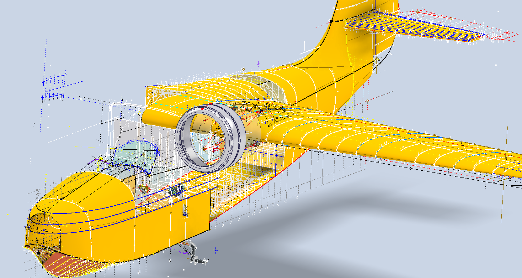
The surface panelling is being implemented in a series of carefully planned stages to effectively accommodate the significant variations in surface contours that occur along its length. To achieve optimal curvature continuity for the surface panels, I have undertaken the modelling of multiple fairing contours, each meticulously designed to ensure a seamless integration with the underlying structure. This approach not only enhances the aesthetic appeal but also ensures structural integrity, as it allows for precise adjustments that align with the dynamic shifts in the surface geometry.

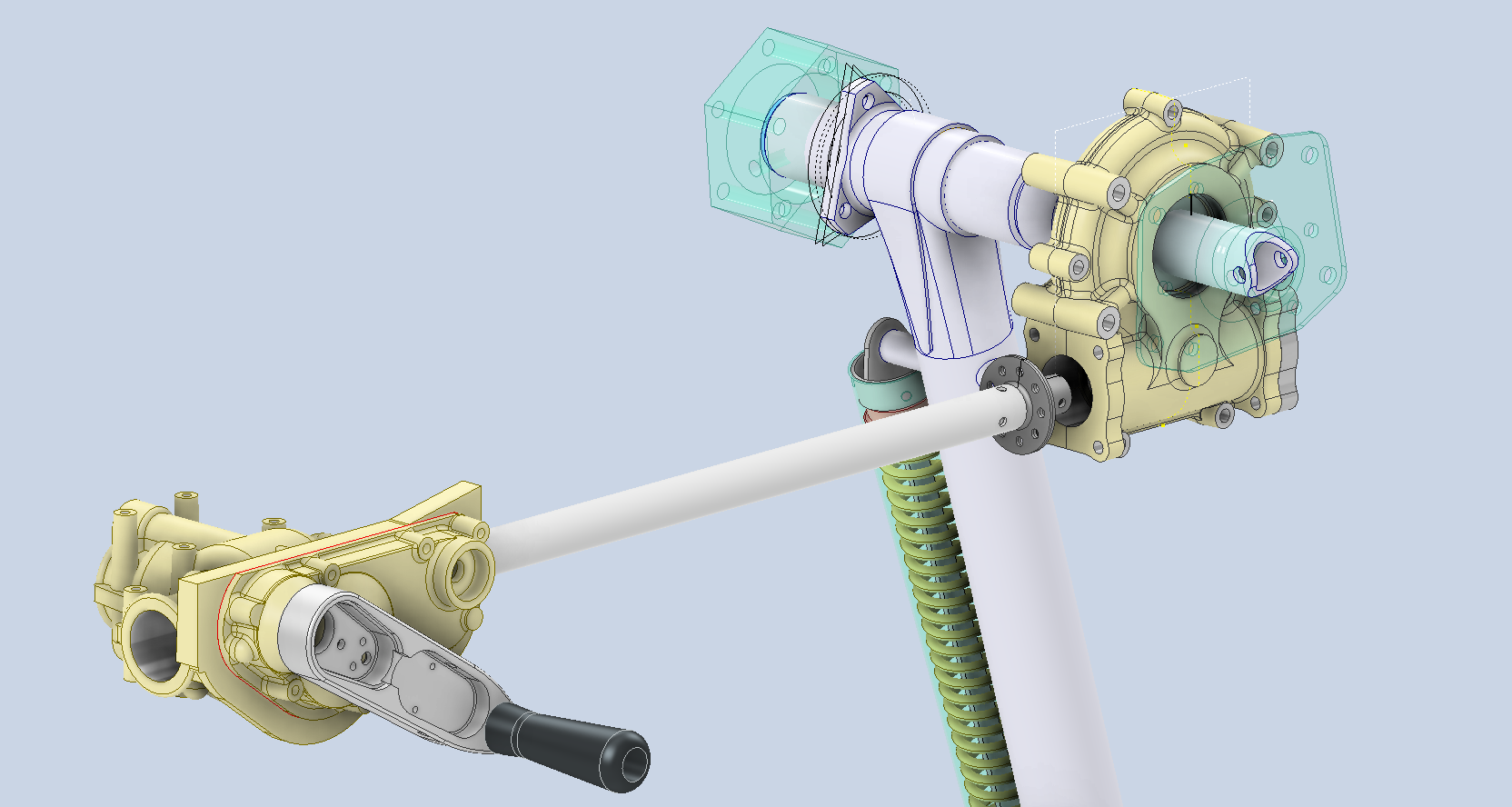
The Landing Gear will be fully modelled, including detailed working mechanisms that will later be the driving parameters for a deployment simulation.

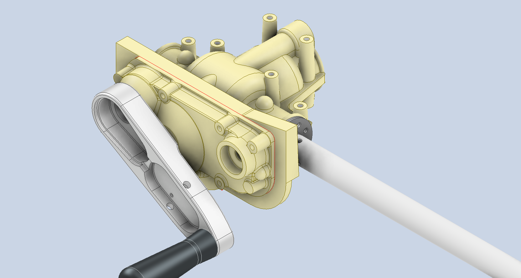
I am currently exploring various options for replicating the components as high-quality 3D prints. This initiative is part of a future project aimed at demonstrating operational criteria in a tangible, physical form. I plan to utilise advanced 3D printing techniques and materials to ensure accuracy and durability in the prototypes. Additionally, I will conduct thorough testing to assess their functionality and performance. This approach will not only enhance the visual presentation but also provide a practical, hands-on experience.

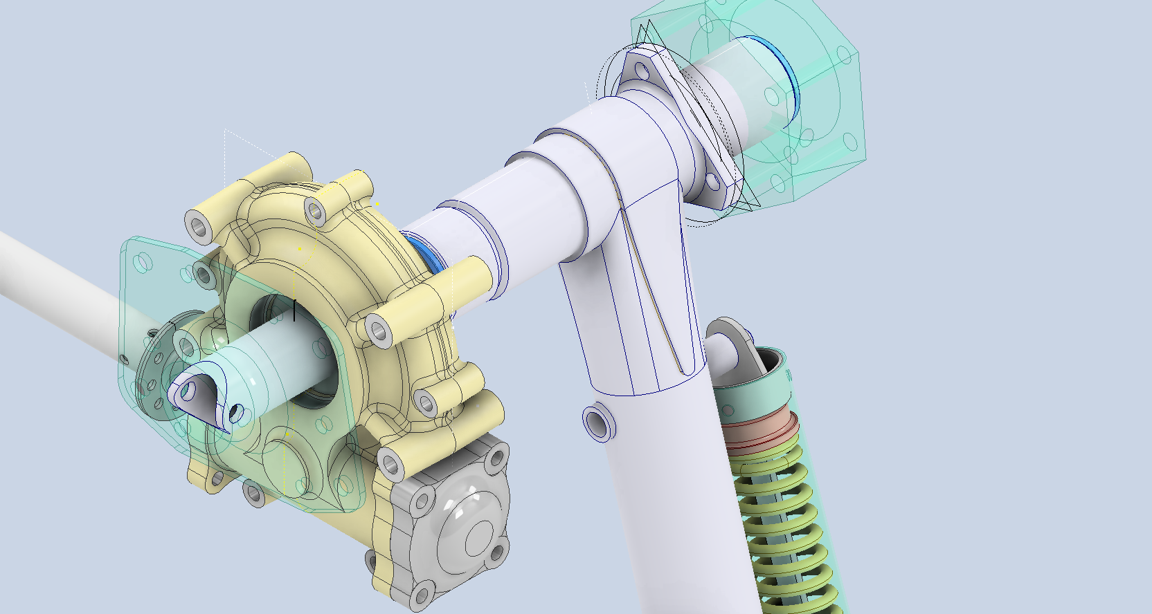
As a basic test to check the viability of the project, I 3D printed the front cover of the secondary gearbox to see how it worked out.

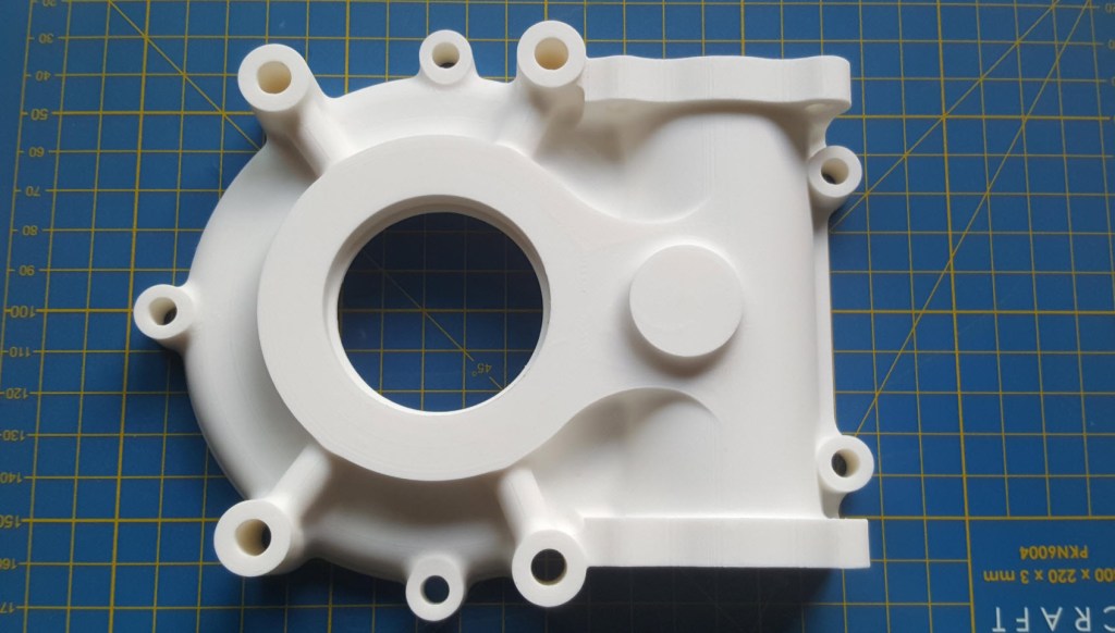
Part #9632 front cover. Printed on an Elegoo Centauri with 0.12 layer height using PLA+ filament. The surface was surprisingly smooth with good dimensional accuracy. Eventually, I will print all the internal gears and check operational criteria.

The engine nacelle is still very much a work in progress, which I will feature in a future post. Following the example of the SU-31 project, the Grumman Goose will also be available in a 1/16 scale version suitable for RC projects.

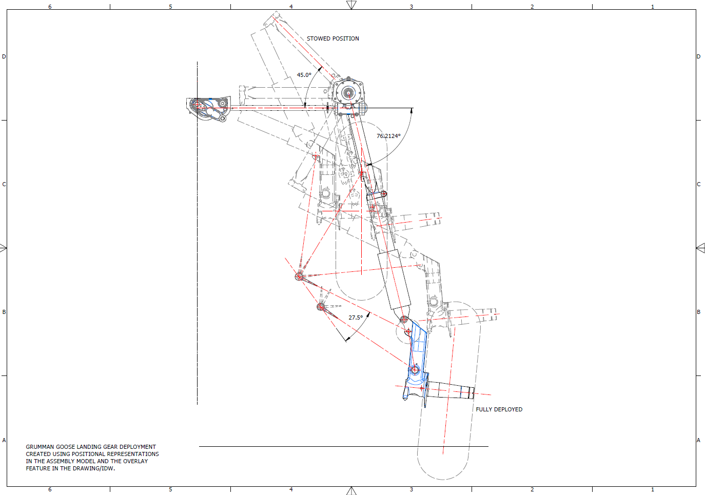
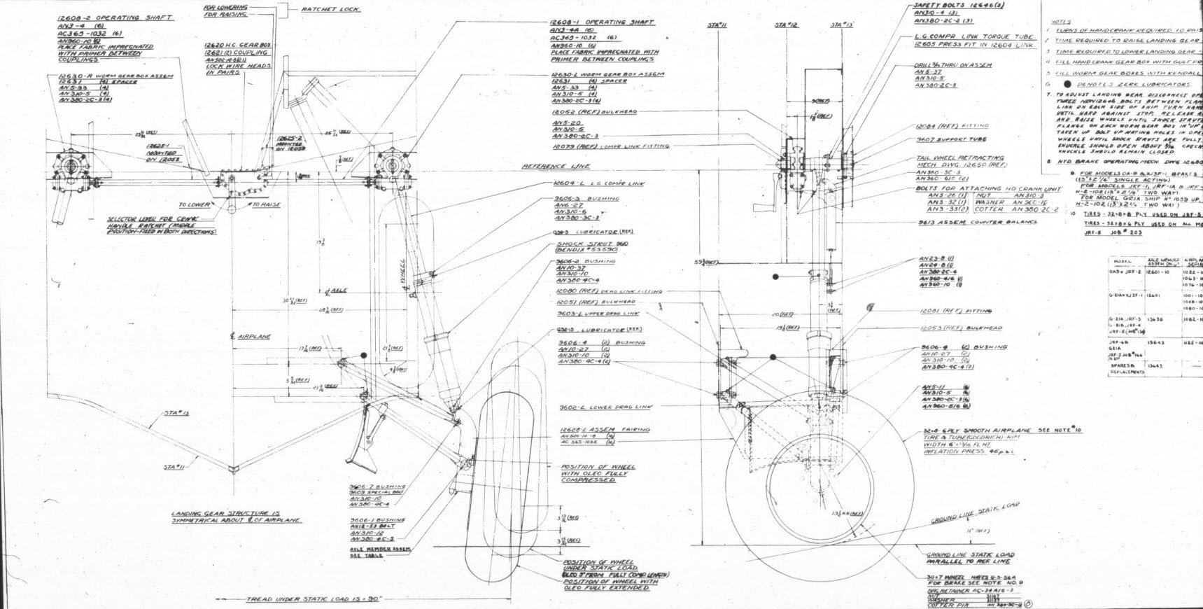
For reference, this is the Landing Gear Assembly Drawing #12600.

Landing Gear Deployment Positional Representations:

This drawing, created in Inventor, utilises positional representations in the assembly to illustrate the Landing Gear deployment.

Technote: 3D Printing-My Perspective #2

Technote: 3D Printing-My Perspective #2:

In my previous article, I talked about finishes, minimal wall thickness, custom supports, and printing dowels. I explored the minimum wall thickness with respect to 3D printing options for a scaled RC aircraft, where the CAD and coordinate datasets serve as valuable resources. My preliminary investigations suggested that a minimum of 2 wall loops with a suitable infill may be the way forward.

I ventured to do some 3D prints to see what actually worked, and though my initial ideas had merit, I have found that for the wings and stabilisers, at least a single wall with a gyroid fill provides structural integrity whilst minimising weight.

In the first image above, the Gyroid fill consumes 10% volume, sufficient to fully support a thin single wall. I actually printed a second test using the more traditional rib-and-sheet construction, but for this type, the walls are too thin, as the ribs created indents on the surface and were not as strong. For the latter, I also tried 2 wall layers, but even then, the surface finish was not as good. It could be argued that it does resemble an actual real aircraft look, but this is an RC project, and the key objective is strength with minimal weight. Using a gyroid fill, we can achieve distributed support across the entire wing with no surface deformations.

My second test was to print half the fuselage with a section of wing to see how this worked out with a single wall. Although it looks just fine, there was evidence of distortion in the straightness of the fuselage, though it was surprisingly strong. The layer lines from the 3D printing followed the longitudinal axis along the fuselage, which created some obvious surface deformations. Ideally, the fuselage should therefore be printed with the layers perpendicular to the fuselage axis to achieve more exact surface contours.

The fuselage will, of course, need to be hollowed out for the engine and RC gear, which then leads to how best to manage the creation of the walls. My initial thoughts are to build this fuselage in sections with a wall thickness of 2 to 3mm printed with double wall layers and gyroid fill. That needs to be tested once I complete the internal design for fitting RC equipment and controls. The plan is to study 2 aircraft, the SU-31 and the Grumman Goose.

The SU-31 model displayed here is a surface model derived from the main assembly. Since this is a part file containing all the surfaces, I can create solid parts suitable for the 3D printing process from any combination of these surfaces without affecting the main assembly. It is crucial to handle this as a separate entity, as the primary purpose of the main assembly is to accurately represent the real aircraft.

The Grumman Goose study is still a work in progress. The fuselage lines are displaying some small misalignments, which are due to the original dimensions being in inches, accurate to 1/32″, which, for manufacturing, is fine, but any imperfections do show in the CAD model. The SU-31, by comparison, was entirely generated mathematically, which resulted in a better CAD model. I did spend considerable time on the wing fillets with micro millimetre adjustments to improve the surface curvature and continuity.

Having explored the 3D printing options, I am now ready to move to Phase 2 to determine the ideal scale for the model and thus the selection and installation of the RC equipment. The following 3-view shows the overall dimensions for reference.

Update 10 Nov 2025:

I have converted the surfaces into solid parts and subdivided them as shown below. The divisions for the fuselage are still pending until I finalise the choice of RC gear. I am still undecided on the Landing Gear; hopefully make a decision on that shortly.

Support Phase 2 Development:

To date, I have only ever built gliders with basic controls for flight…I actually designed my own glider at one stage. I have never built a powered RC aircraft, so this project is going to be a challenge.

STL, DWG, and IGES files for the completed CAD model at a 1/16 scale will be available soon. Please see the new post above for details.

I would love your support as I dive into these exciting projects! If you’re able, a small donation would mean so much—every little bit helps and makes a big difference. Thank you for considering!

Dinations Paypal preferred; PAYPAL LINK,

As usual, comments and inquiries to hughtechnotes@gmail.com