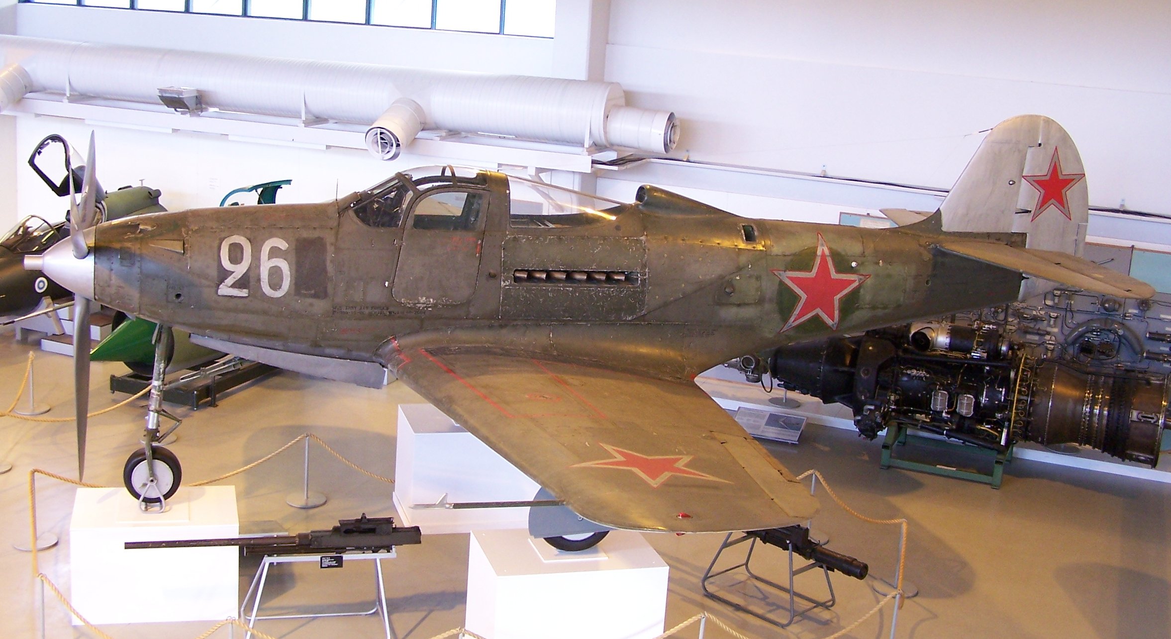
“SIMFEROPOL, September 25. / TASS /. An expedition of the Russian Geographical Society (RGO), together with the Russian Ministry of Defense, lifted a Bell P-39 Airacobra fighter from the bottom of the Black Sea from the regiment that took part in the air cover of the Yalta conference of leaders of the anti-Hitler coalition in 1945, a specialist from the Expeditionary Center of the Ministry of Defense Anatoly told TASS on Friday Kalemberg.”
As many of you know I am a huge fan of the P-39 Airacobra. So I was particularly interested to read these reports of the recovery of this P-39 from the Black Sea. These are the links to the articles I have read so far from various news publications.
If anyone has any further information to share on this project please drop me a line and I will feature updates in future articles; perhaps even progress on the restoration.
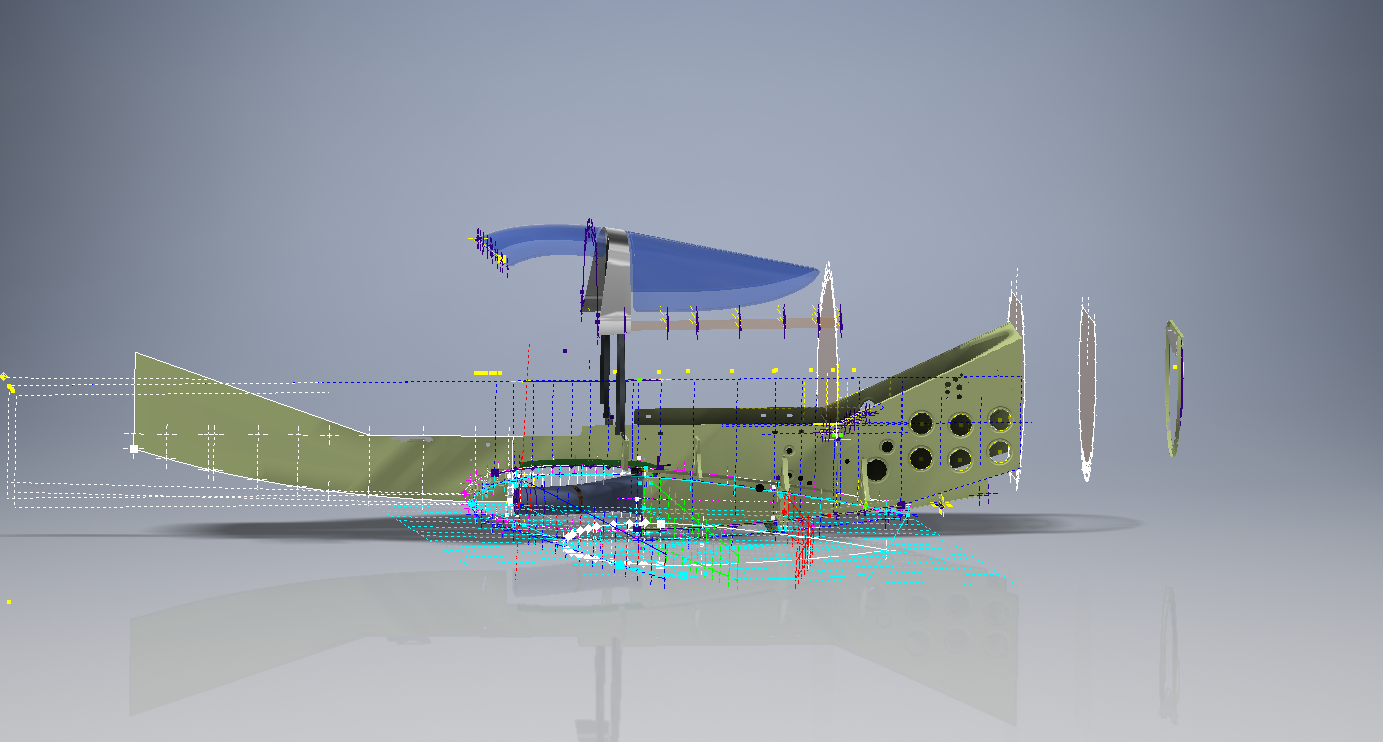
Progress to date has focussed on the main inner fuselage development with additional modelling to the top cockpit glass.
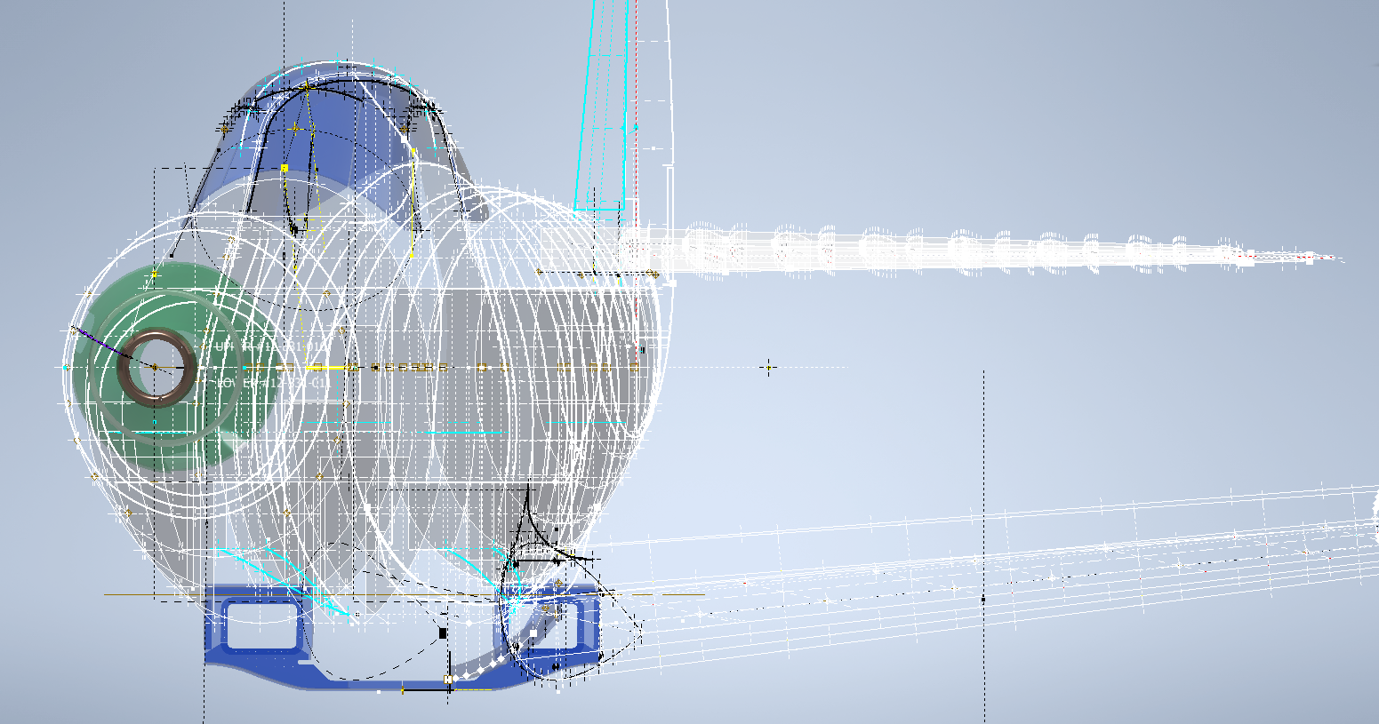
Just for comparison and to give you some idea of scale and context I thought it may be prudent to bring together a photograph of the P-39 and the CAD model, that are roughly shown from the same viewpoint.
Ordinate Observations:
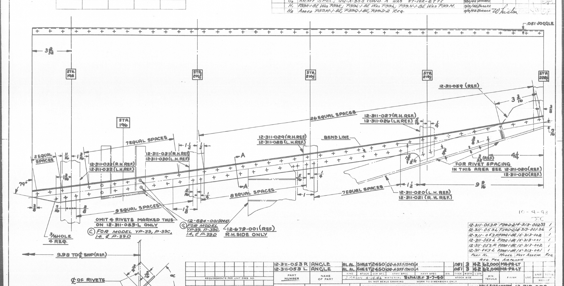
I mentioned before that we don’t have an ordinate plan for the P-39 as the main ordinates are incorporated within the Bell part drawings themselves. One of the key objectives for this project is to create an ordinate plan for the main fuselage to ensure that everything matches perfectly. Typically for all manufacturers of this era, the Bell drawings are accurate to 1/64 inch (0.4mm) in some cases but more generally dimensioned to only 2 decimal places of an inch that occasionally results in some minor alignment issues.
An example is as follows:
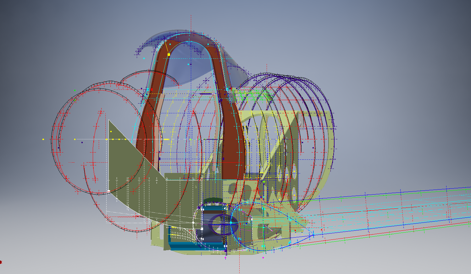
The upper structure for the cabin has ordinates setout for defining the contour of the main structure which overlaps the fuselage outrigger as shown. The fuselage outrigger profile does not quite match either the dimension nor the curvature in this instance.
If we look at the ordinates for each part; as stated on the original drawings; we can see the difference is exceptionally small although well within the manufacturing tolerances.
WL (waterline) 12: Cabin noted as 16.98in – Fuselage noted as 17.006in
WL (waterline) 16: Cabin noted as 16.26in – Fuselage noted as 16.286in
The difference is only 0.026in which equates to 0.6mm. Admittedly some ordinates are given to the outside of the skin, others are not and it’s tempting to suspect that the variation is due to this. The skin though is 0.04in almost twice the difference.
Working with CAD these variations are quite obvious and ideally need to be sorted otherwise we end up with all sorts of interferences with adjoining components. This makes it rather interesting and challenging in order to derive a satisfactory model.
In this example the curvature analysis shows this point close to being negative curvature in the left image based on the ordinate value of 12.88in. We know that this dimension is a decimal equivalent of 12 7/8 inches which at 3 decimal places gives us 12.875.
Changing the value thus to 12.875in smoothes the curve in line with expectations.
The majority of the Bell P-39 drawing dimensions are in fact very accurate, with the first example above being the exception rather the rule. This is an update of the ordinate developments for the fuselage which is derived from multiple part drawings.
The Bell P-39 Airacobra archive of drawings is very comprehensive, comprising in excess of 10,000 good quality drawings. Probably one of the better quality archives available, for further details send me an email to HughTechnotes@gmail.com
.Technote: Bell P-39 Creating Wing Fillets.(Inventor 2017)
Wing fillets are probably one of the most complex aircraft items to model as they need to follow the curvature of both the wings and the fuselage shell. Invariably we have many offsets to contend with and variation in angular alignment of the flanges.
The following images are typical of the manufacturers drawings with an ordinate table listing the X,Y ordinates and angle of the flange at each point.
As usual we would start with marking out what we know; in this case the ordinates points from which we create the reference geometry.
The reference geometry in this example is the 2 splines for the flanges connecting to the fuselage (left) and the wing (right) with a horizontal base line for the lower flange.
We then check the curvature of the splines to ensure we do not have negative curvature; adjusting the handles to negate this where necessary.
These Fillets are full of tangent and perpendicular dimensional oddities that can sometimes be a real pain to achieve satisfactory results .
Previously we would create a work plane (tangent) at each node and individually sketch the required flange construction lines set to the correct angular value. This was a lot of work and a heck of a lot of sketching. Thankfully Autodesk have introduced some nice functionality to the 3D sketch environment in Inventor 2017 making this task so much easier with provision of logical constraining options and associations.
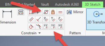
In Inventor we have various planar constraining options as shown. The top one is to constrain a sketch element to a surface and the lower ones are parallel constrain options to the main work planes.
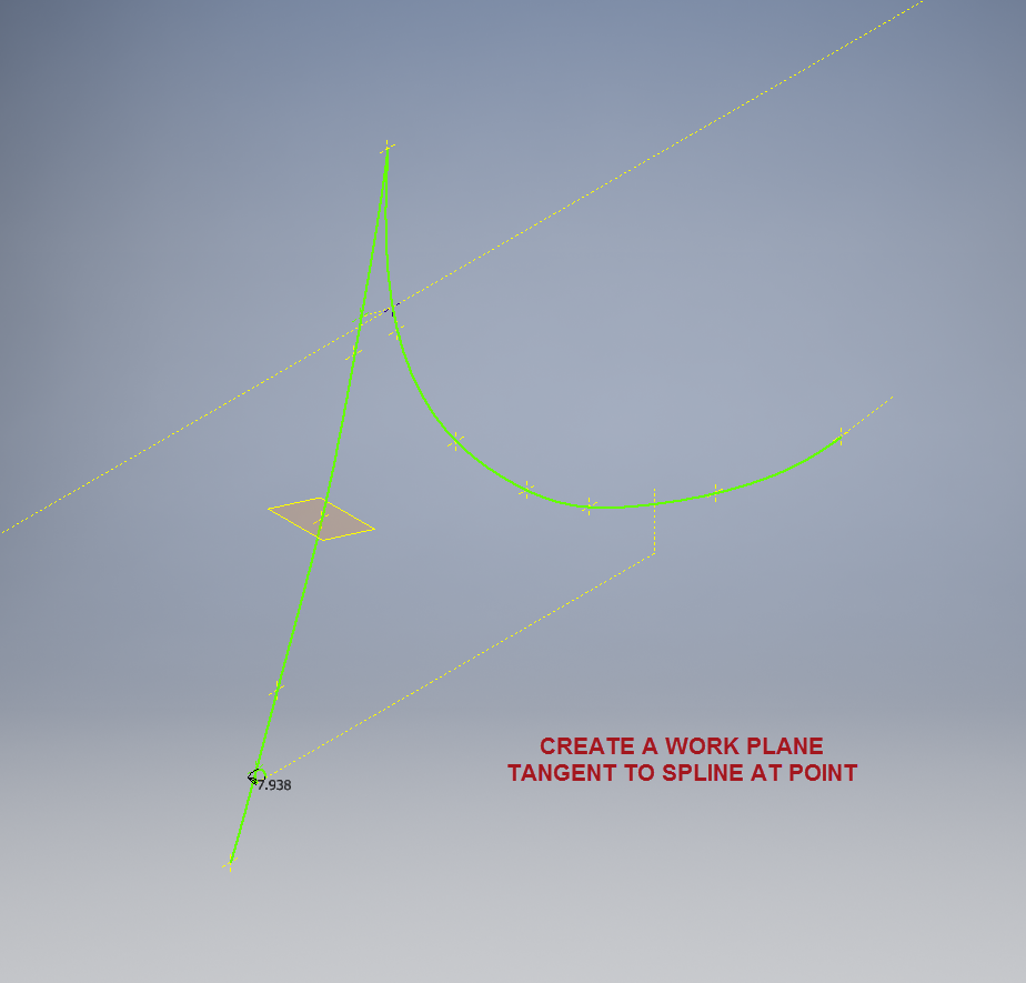
We would still create the work planes tangent to each point as before; I have shown one for clarity, then we simply move straight into the 3D sketch environment to model all the flange construction lines.
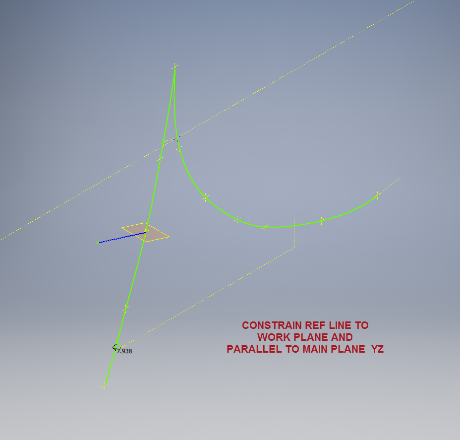
We first need a reference base line constrained to the tangent spline work plane and also be parallel to the main work plane YZ.
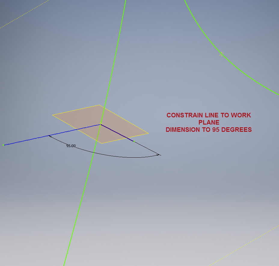
We then sketch the flange line, constrain to the tangent spline work plane and dimension to the reference line as shown at 95 degrees.
It really is a simple case of drawing a few lines and just using the planar constraint options to ensure correct tangency for developing the flange guide lines. Furthermore you don’t even need to project geometry from the 2d sketch as you place the line it will automatically connect to a point on the 2d sketch.
We continue doing this for all the ordinate points as shown then surface loft the flanges and apply a surface patch to create the main body. I should note that the surfaces shown have already been trimmed to the extents of the part.
It is very tempting at this stage to stitch and then thicken to achieve the finished part, however in my experience occasionally the transition of sharp corners introduces anomalies along the edges which can be negated if we first apply a fillet prior to thickening.
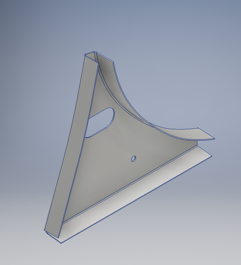
To finish the part after thickening, I converted to a sheet metal part and added a flange to the base at 7.5 degrees, a few holes and that’s it done. There are some flange holes still to be modelled which will be done later when the other connecting parts are modelled and checked for alignment in the assembly.
Progress Update:
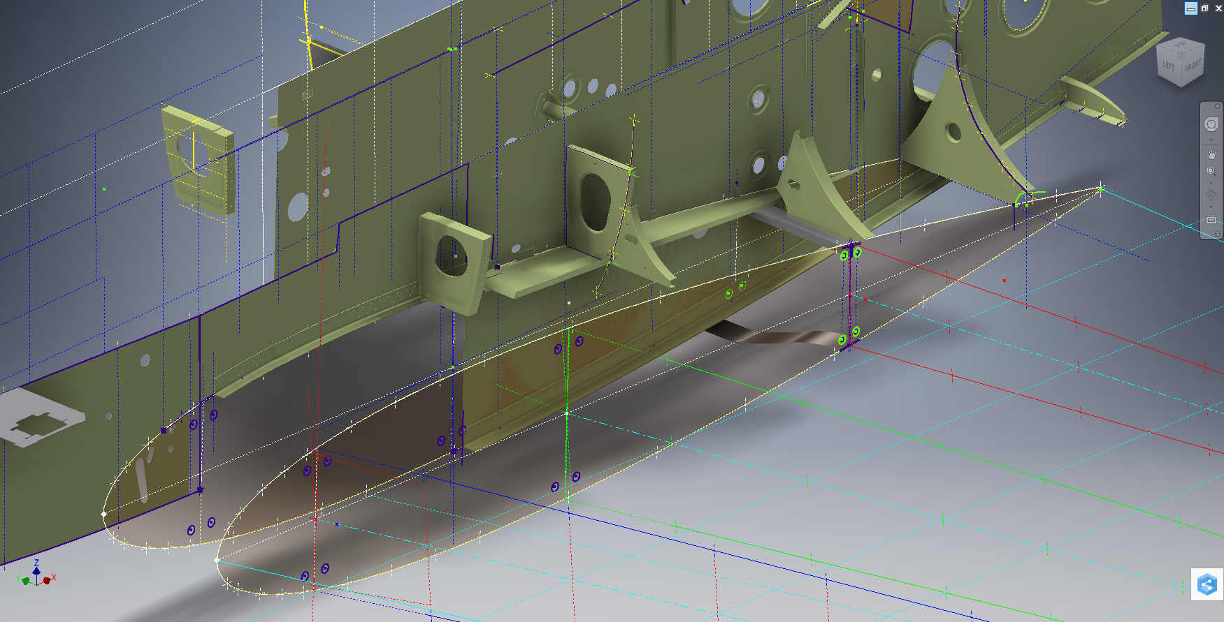
The following image shows a typical interface check between the P-39 wing and fuselage:
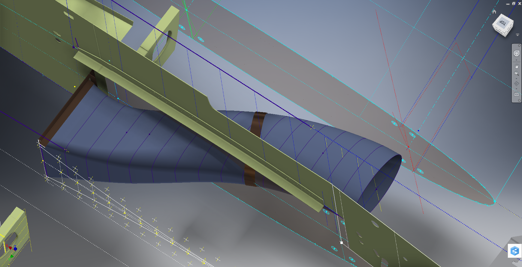
…and here the Radiator Intake Duct, preliminary alignment:
This radiator intake duct was an interesting development as the Bell chaps had provided both the tangential and the exterior dimensions at 2-inch intervals; on plan and elevation; which collectively are projected to form the profiles at each station. The white sketch at the bottom of the image shows these dimensions on the side elevation, with the curved lines depicting the tangent lines. I checked the curvature of this line and I only needed to adjust 2 dimensions by a minuscule amount to correct for negative curvature.
Update July 2022: New Revised P-39 Ordinate/CAD Dataset:
For all inquires please get in touch: hughtechnotes@gmail.com