Sopwith Pup:Wing Brackets

SopwithPup: Wing Brackets

This was not meant to have been a study in its own right, but out of curiosity I couldn’t help but wonder if there was enough information to actually build an accurate 3D model.

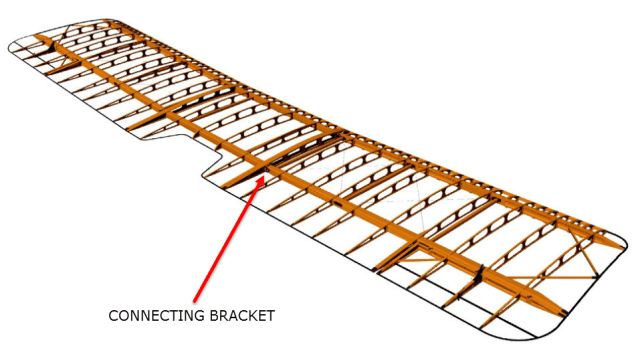
I was also curious why I had received a number of help request emails from my friend about this particular aircraft…so I decided to have a closer look. His latest query was regarding brackets similar to the one I mentioned in my previous post but specifically the centre section connecting brackets to the wings.

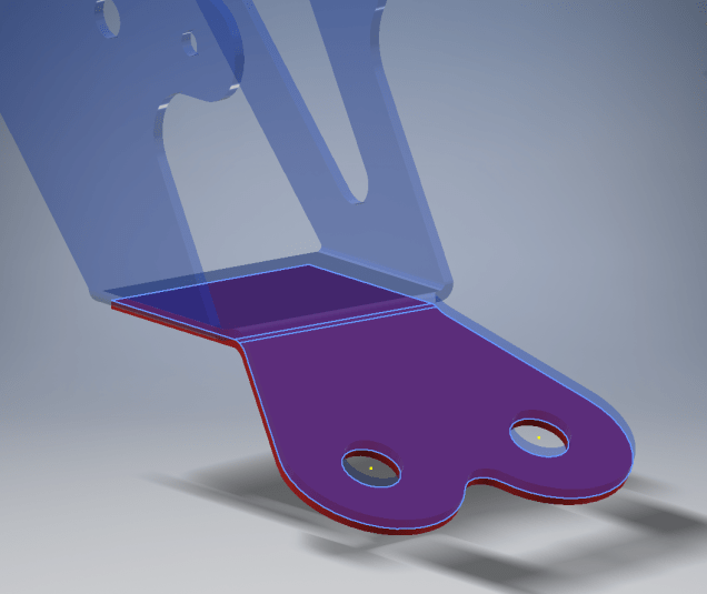
The left bracket belongs to the centre section and the right bracket is the connecting bracket for the wing that slots into the centre section bracket.

sp-009

The bracket dimensions are such that the centre bracket sits proud off the centre spar whilst the wing bracket is embedded in the wing spar, so technically they should just fit into one another without too much problem!! That’s the theory but the reality is it doesn’t quite align with expectations.

sp-03

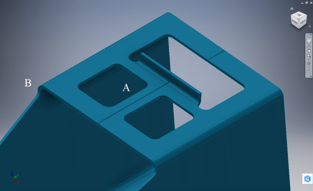
This image shows the actual clear dimensions within the top and bottom rib flanges which replicate the perimeter dimensions of the wooden centre spar. In order for the centre section bracket to connect to the spar we would have to notch the top and bottom rib flanges to get it to fit. The horizontal dimension can vary (highlighted) but we will be restricted by the vertical dimension. I can’t imagine why anyone would want to notch the top and bottom flanges as this diminishes its strength. Plus there’s another issue with this…

sopwith-pup06

This preliminary model shows the problem where the centre spar is actually set back one inch to facilitate the incoming connecting bracket from the main wing. Ideally, we need to fully assemble the centre section and have it fitted to the aircraft and aligned prior to fitting the wings, but how can this be done if we can’t screw the rib flanges to the spar? I think in this instance I would shape the wooden spars in such a manner as to facilitate fitting of the flanges and mating with the wing spars.

I have done some research on this and it appears to be a known issue with some clever blokes just redesigning the connectors to make it work better or tapering the wing spar to good effect as shown below.

sdasmpup

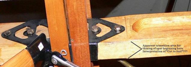
It looks as though the wing spar is tapered with a smaller bracket sized to fit within the centre bracket. That would work and likely an improvement implemented in the workshop. A very rough preliminary study could look something like this…

…it does need a lot more work but I don’t have a lot of time to develop it further right now!

The design in many respects seems a little rough and ready, but we have to remember in those days they were under a huge amount of pressure to get these aircraft built and get them into the field. The life expectancy of these aircraft was only six weeks so replacements had to be shipped out in rather a quick time.

No disrespect either to Tom Sopwith and his engineers, these things actually flew rather well regardless of the vagaries of the design and what may seem to be annoyances to us may well be things they would naturally deal with in the workshop without any hassle.

It is very tempting to continue developing the Sopwith Pup but to do so efficiently would require setting out the basic geometry for the entire aircraft, identifying the anomalies and determining suitable resolutions as close as possible to the original design intent. I’m not sure I have the time nor the inclination to do so.

This has been a welcome distraction from the P-39 Airacobra project and will likely feature in a few more posts as I will surely continue to receive help requests from my good friend.

Sopwith Pup: Technote

Sopwith Pup: Spar Clip Technote

The Sopwith Pup is a single seater biplane built by the Sopwith Aviation Company, another aircraft in my archive, though not one that I have done much work on. This is just a quick technote; so not a new project; my priority still lies with the P-39 Airacobra.

I received an email from a close friend and he asked if I could help him out with this model for the main spar clip, item number 1393-1 from the Sopwith drawings. The area in question was the cable lug at the base of this clip, which comprises 2 parts.

The problem related to matching the profile of the top part to the profile of the lower part, without extensive or complex modelling. For the lower part, I decided to use the sheet metal features to create this as a multi-body part which I would then use as a template to profile the upper section that is essentially an extension of the main model.

What he was trying to do was project a sketch from the each face of the lower part, extrude each sketch and then fit a bend to connect the two extrusions. He reckoned this was more complicated than it should be and asked me if there was better way of doing this.

He was actually not that far from achieving a simpler solution, he just needed to adapt the process a little bit.

sc-03

In a previous article for the P-39 cabin glass I discussed the merits of selecting the solid surfaces as a means to modelling the jogged edges. I have used a similar technique here for developing the upper part of the lug.

Simply by selecting the top surfaces of the lower part as shown above; we then apply a thickness to this selection and opt to merge with the upper part as shown. There we have it; an exact match and fit between lower and upper lug parts in one step!.

It looks simple and often the best solution is, but occasionally it is easy to overlook the fact that we can manipulate the surfaces of a single solid model to create new separate parts without too much effort.

sp-05

Squaring the Edge:

The Sopwith drawings for this part and many other similar parts are a little misleading given that they show the edges of these components as beveled. This is normally not good practice, particularly when metal meets timber. Ideally we need to square the edges to negate this problem and to facilitate the cutting of the developed sheet metal pattern.

sc-06

These brackets are an awkward shape which requires some careful planning to ensure that the model is correct and can be manufactured. So to achieve this I occasionally use surfaces to set-out the basic cut profile shape and then thicken.

Thickening a surface model is actually a good way of working due to the thickness being applied normal (perpendicular) to the surfaces, thus by definition achieving a good square edge to the developed pattern.

As you can see in the image on the right the edges are square and easy to cut.

The other way of doing this is using the cut option feature from the sheet metal command.

sc-10

By selecting the “Cut Normal” option in the dialogue this will ensure that each of the edges from this extrusion will be square to the surface when flattened.

Whilst we are on this subject; the weld seam at the top of this bracket is something I would consider improving by having a thin continuous metal strip either side of the seam instead of 3 smaller widths (top image) which may distort the metal, something like this (A):

sc-11

Notice I have tidied up the bend at (B)…this gives a much cleaner profile when the draft angle is quite small. I should note that I don’t normally take liberties wth the manufacturer’s details, but occasionally exploring options to see how things could be improved can be quite an interesting exercise.

I should note that it is normally good practice to state on the 2D manufacturing drawing a “Break Edge” minimum size anyway for all edges even when square cut.