Developing 3d models of historical aircraft is both challenging and sometimes frustrating, often requiring inventive, creative thought to develop complex shapes commonly associated with aircraft designs.

One key aspect that has given me some grief in the past is when the fabrication drawings show a developed panel alongside the details of its final curvature. In a workshop one would just cut this plate and then form it on a predefined template to create the finished product.
This image illustrates a typical example of the sort of thing I am talking about. The large detail shows the flat pattern or developed profile with the top details showing the curvature required for the finished product.
I had tried various ways of doing this use the Flex and deform options to control the curvature within the dimensional limitations as noted – without success. I finally decided to try the Wrap command – essentially the same methodology used in the real world.
This Technote will describe the process I have adapted to develop these shaped forms.
For the purposes of keeping things simple I am not going to attempt the above but something a little easier.


I created a spline and then extruded to give me a surface representing the finished curve.


The next step is to create a plane tangent to the curved surface selecting the point at the bottom left corner. This is important; the plane has to be Tangent to the surface and a point selected that is coincidental with the alignment of the sketch. The sketch as shown is aligned with the bottom of the curve which is coincident with the datum for the plane. The reason why this is critical is that when the sketch is projected the lines deform to fit the surface which depends on the distance from the surface and the relationship between them – by selecting a coincident point where the sketch meets the surface then deformation is zero.

Inset>Features>Wrap – select the ‘scribe’ option and the 2d profile is ‘wrapped’ to the surface.
Note: cautionary comment: to check this methodology I did a measure on the left vertical line on the 2d sketch and checked it with the wrapped line on the surface – technically they should be equal – the 2d line measured 37.30194mm and the corresponding line on the surface is 37.29606mm – a variation of .00588mm – well within acceptable parameters.
This is where it gets interesting:


When you select ‘wrap’ in the feature tree the area of the wrap is highlighted and similarly when you select the ‘surface extrude’, but when you check the surface bodies we actually only have one surface!. So how can we progress this to separate the wrap area to enable us to finish the part?
 Because the areas are separately selectable we can use the offset command with a value of zero and then select only the area we want….this creates a copy of the surface at the same location…all we need to do now is apply thickness and our part is complete.
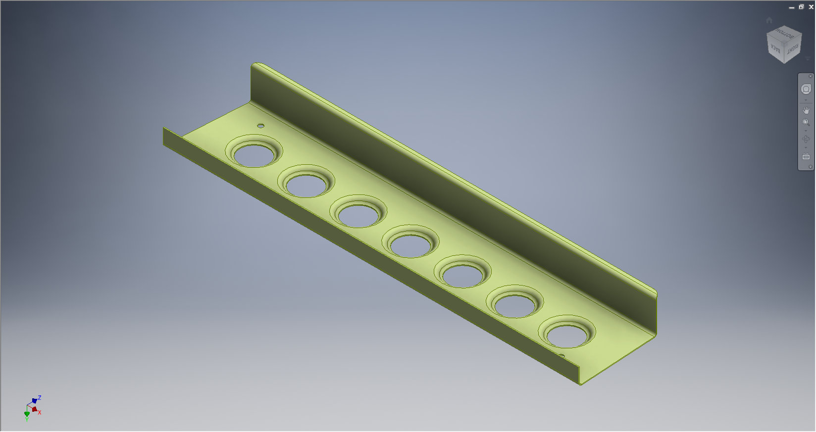
So there we have it! A formed plate that conforms to the defined surface curvature and dimensionally with the 2d plan sketch.
Footnote: Placement of the tangent plane as I mentioned is important, but I suspect that thru experimentation various tangency relationships can be identified that satisfy all the necessary criteria.