Technote: Clean Up 3D Scans:
In 2019, I wrote an article about my experiences using photogrammetry and its applications in historical aviation research. For those interested, the article can be found here: Photogrammetry. Having delved into this fascinating subject over the years, I thought I should share some tips and associated YouTube videos that can help with the preparation of scans for 3d printing.
Museums often embrace exciting scanning techniques to safeguard their precious artefacts, such as the cutting-edge use of laser scanners and the fascinating method of photogrammetry. These innovative approaches not only help preserve history but also bring it to life in new and captivating ways! You will find many museums on sites like Sketchfab with large collections of these artifacts availble for download.
- The Royal Armoury: https://sketchfab.com/TheRoyalArmoury
- Virtual Museum of Malopolska: https://sketchfab.com/WirtualneMuzeaMalopolski
- Mid-Pacific Institute: https://sketchfab.com/midpacificmuseumstudies/models
You might be curious as to why the first two links lead to websites featuring armoury models. In addition to my personal interest in armour and weaponry from the Middle Ages, this subject also illustrates the typical surface profiles similar to those of historical aviation aircraft and their components.
In today’s world, nearly everyone carries a mobile phone, and many of these devices come equipped with high-resolution cameras capable of capturing stunning photographs. This feature proves especially beneficial for those interested in photogrammetry projects, which require detailed imaging to create accurate 3D models. Using a mobile phone for this purpose is particularly advantageous when visiting museums, as it allows for discreet photography without disrupting the exhibit or disturbing other visitors. This non-intrusive method enables enthusiasts and professionals alike to document artefacts from various angles, enhancing their ability to analyse and reconstruct their dimensions digitally.
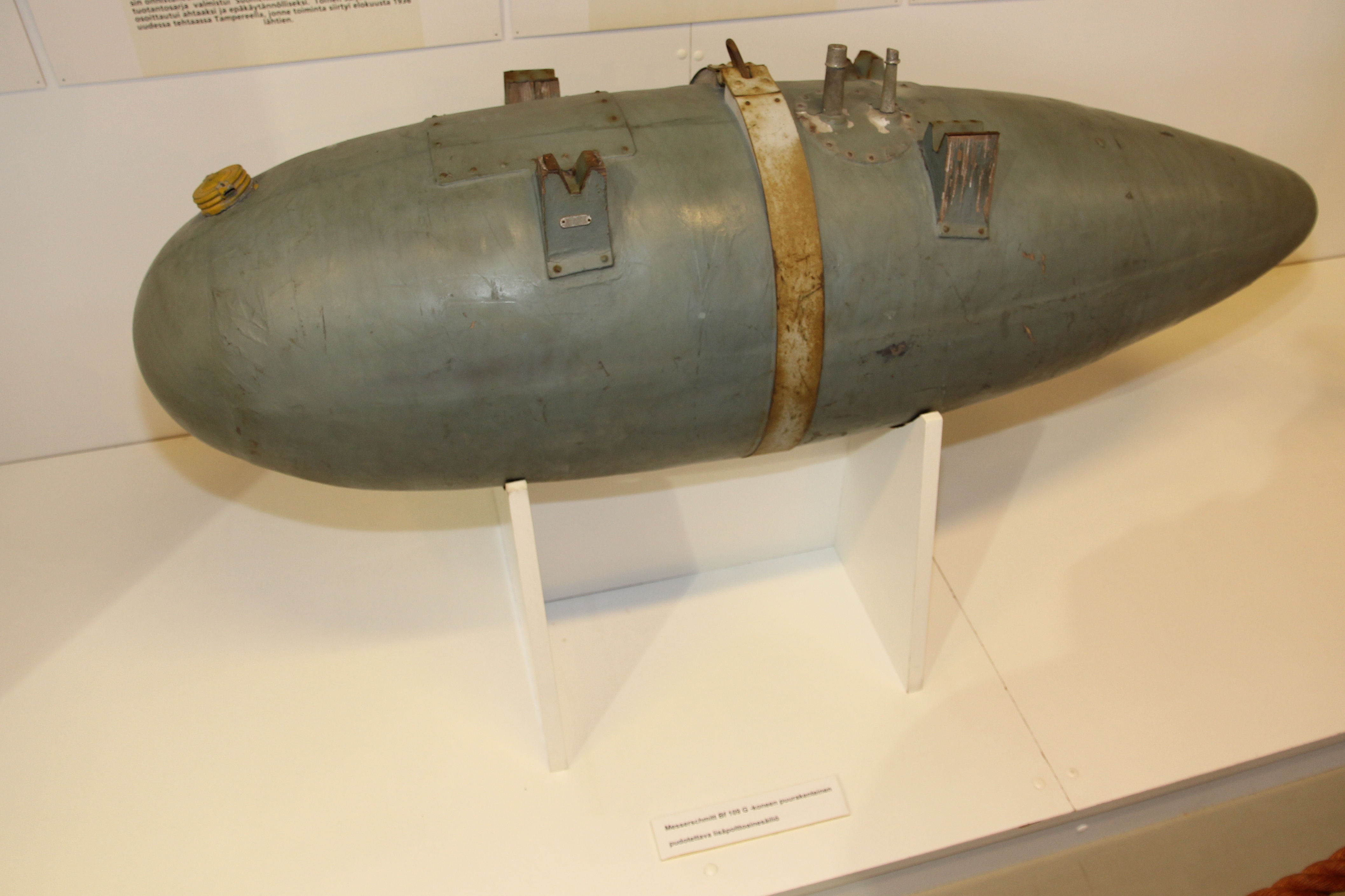
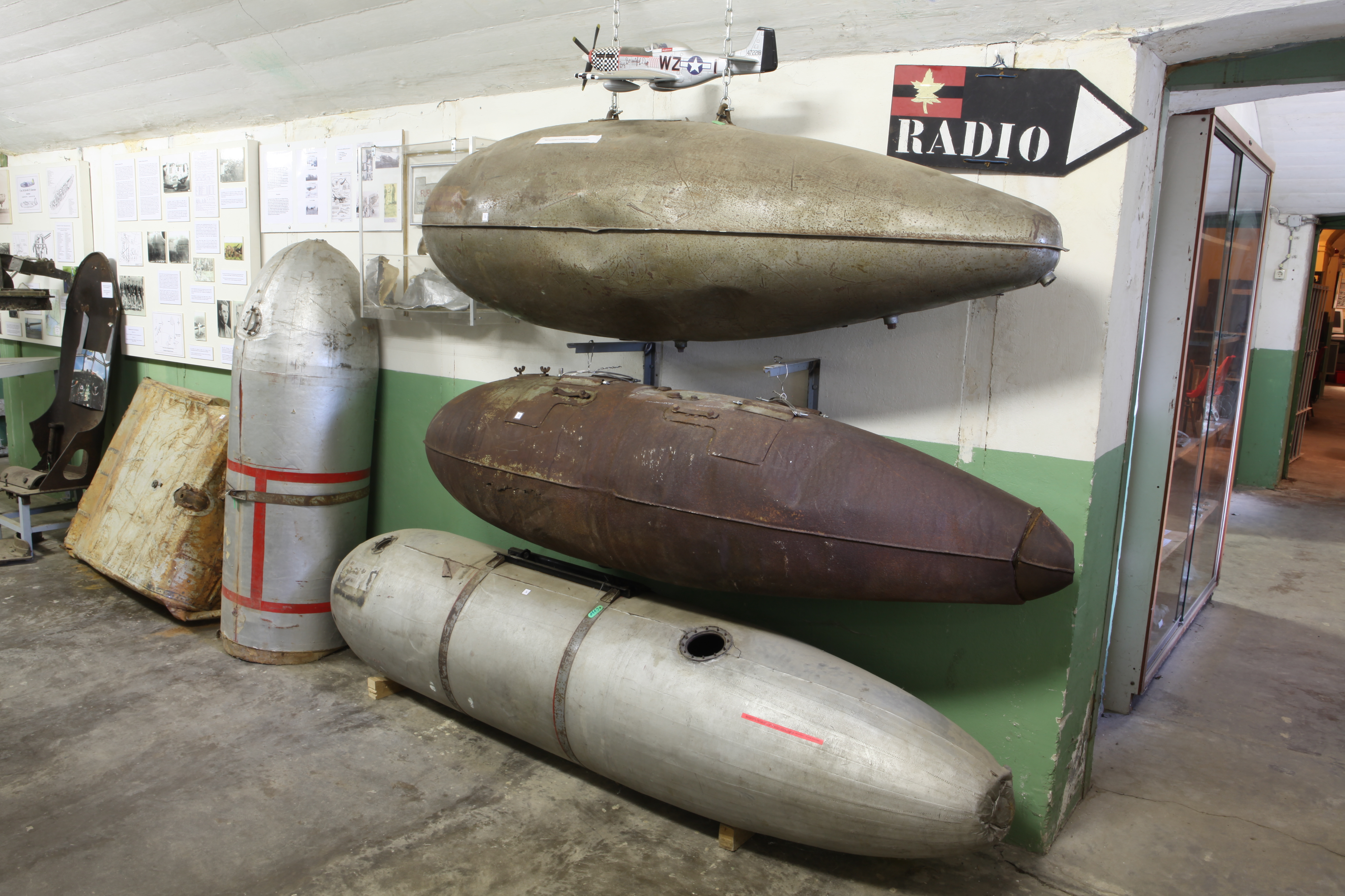
One of my favorite subjects to capture in photogrammetry is droptanks. They are often rusty, making them ideal subjects for this technique. Other great items to consider include guns, torpedoes, and aircraft engine cowls. While you may not have complete access to all sides of a cowl, remember that you only need half of the profile to recreate it effectively. It is also a good idea to carry with you a plastic ruler that you can use for scale later.
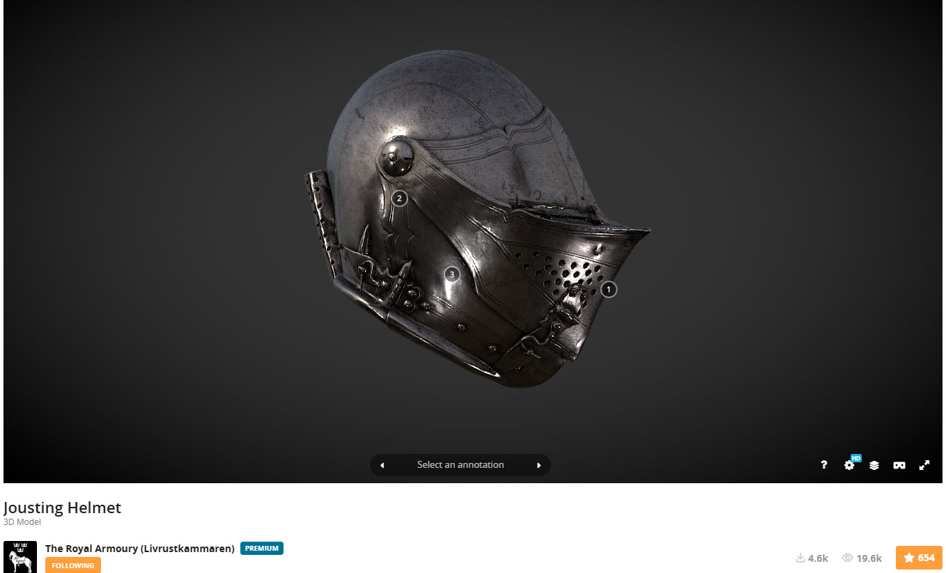
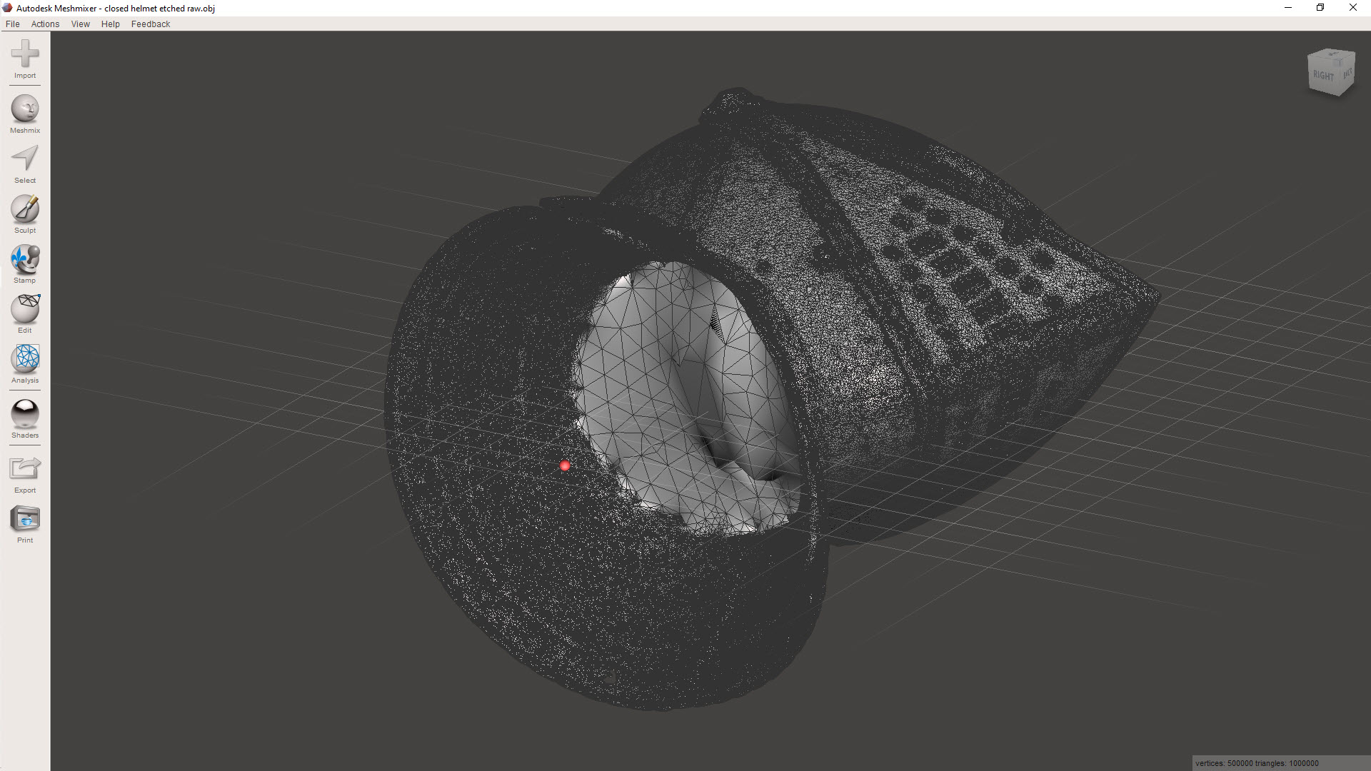
Getting back on subject to cleaning those scans, let me introduce you to the Jousting helmet.
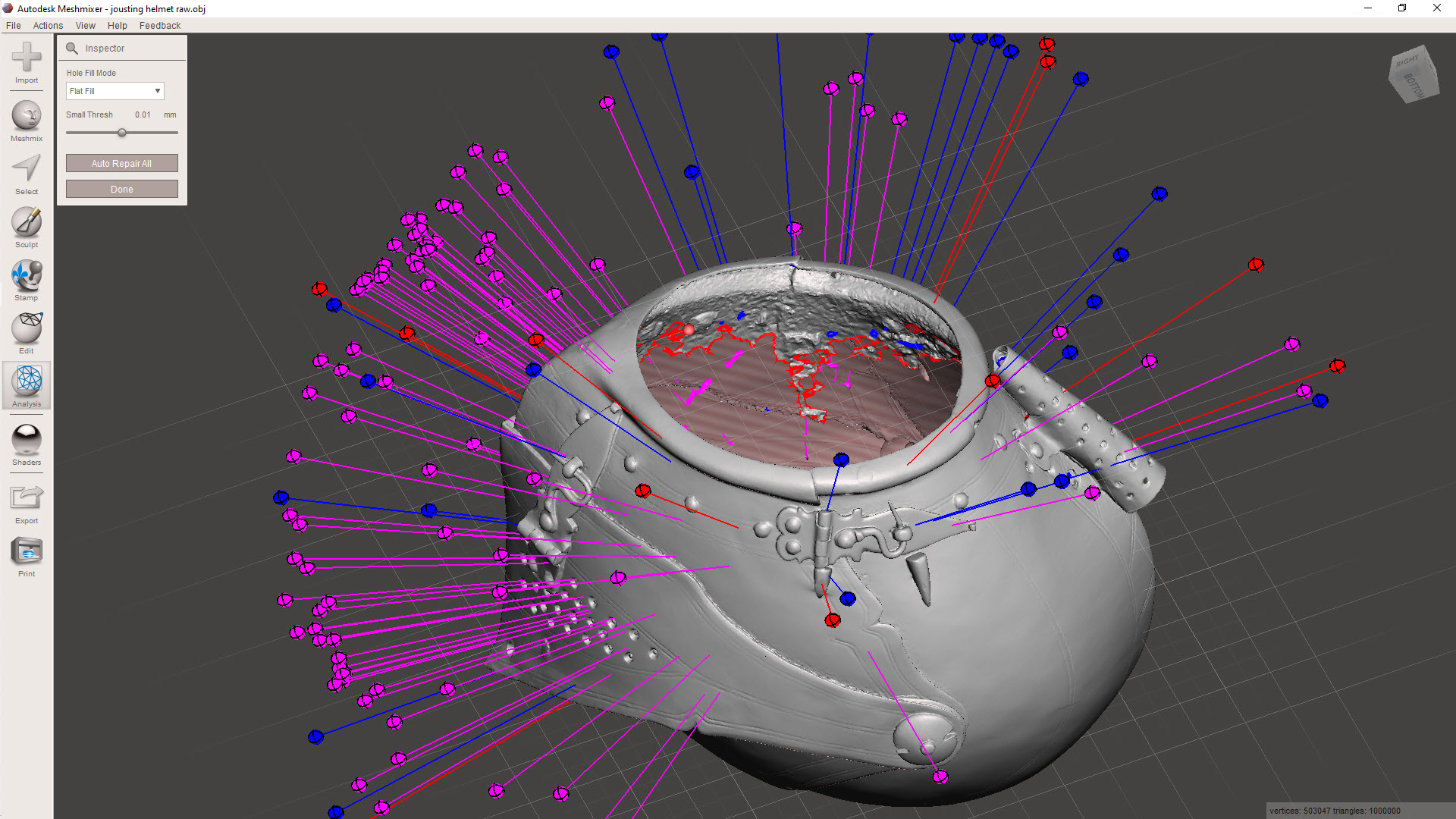
My workflow starts with the Inspector feature in Meshmixer, a free download from Autodesk. This will throw up a bunch of different issues, as illustrated. The blue refers to small holes or inverted faces, the red are potentially problematic areas for resolving, and the magenta identifies loose, unattached meshes. At this stage, you could just run the Auto Repair All, and Meshmixer will do its best to resolve those highlighted issues. Sometimes, though, the results can be unpredictable and may add additional meshing that you don’t want.
Don’t despair, as you can be selective with this tool and initially fix the blue-highlighted areas by clicking on each of the blue orbs. You could click through each of the magenta orbs and select each of the unattached elements one at a time, but there is a better way.
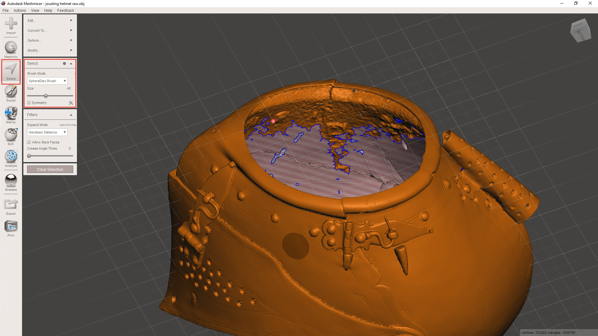
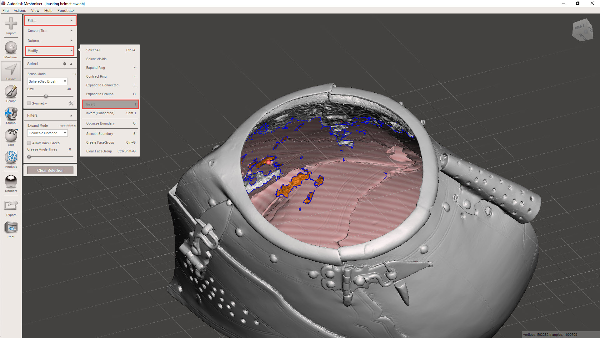
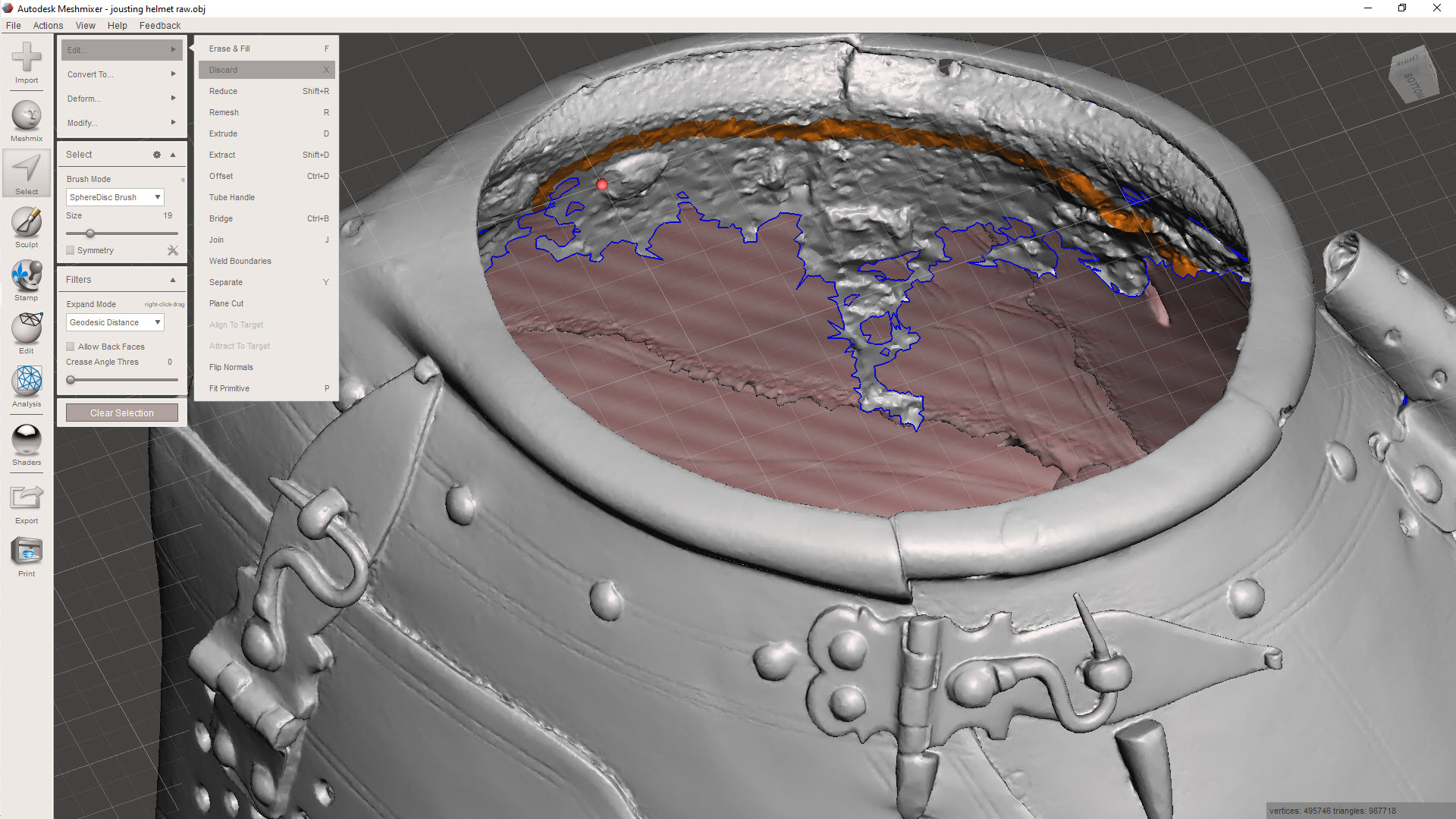
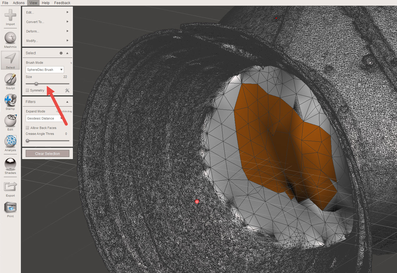
Using the select option, we can isolate the unattached elements quickly and efficiently. First, select an area using a medium-sized brush and double-click to select all attached meshes. A single mouse click will only select mehes within the specified brush diameter. Once selected, go to MODIFY>INVERT to invert the selection to group the unattached items. Then go to EDIT>DISCARD to remove all those unattached items.
This is also a useful technique for tidying up groups of meshes.
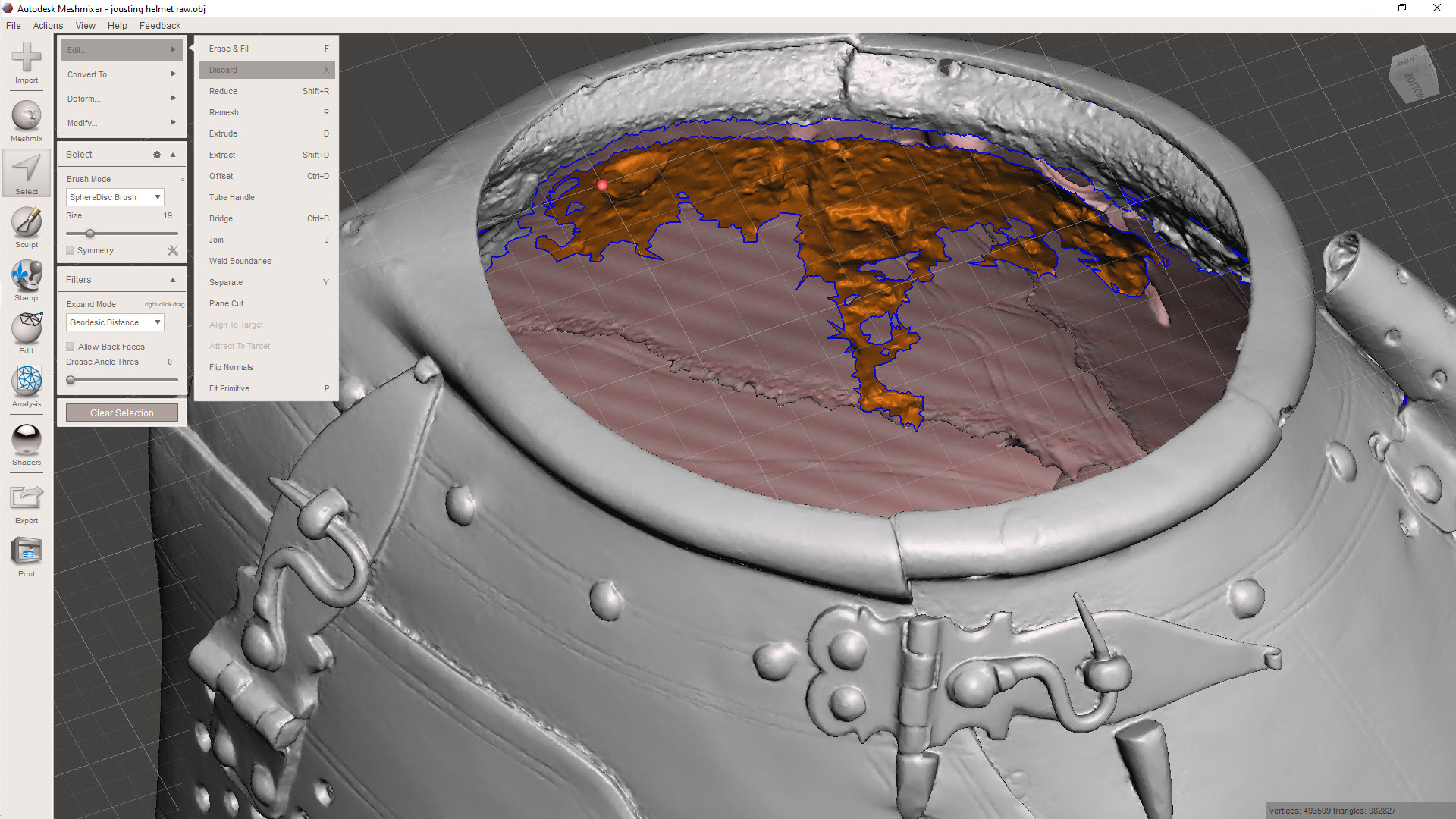
Here, I have selected a row of meshes, essentially a channel cut line isolating the chaotic mass of meshes. Using the above technique to then select the entire body and invert, I can easily remove that mass. Taking my time, I would go around the interior and tidy up the spurious collections of meshes one mass at a time.
For reference, a good YouTube video explaining this in more detail “Meshmixer Clean a Scan”
Sometimes with photogrammtery the conversion programs will attempt to enclose large areas, commonly the base or unscanned regions.
If you need to remove sections like this, selecting the meshes directly and discarding works fine, but you can also just create a perimeter channel, invert and discard accordingly.
Ultimately, we desire a continuous, defect-free surface suitable for applying thickness for 3D printing.
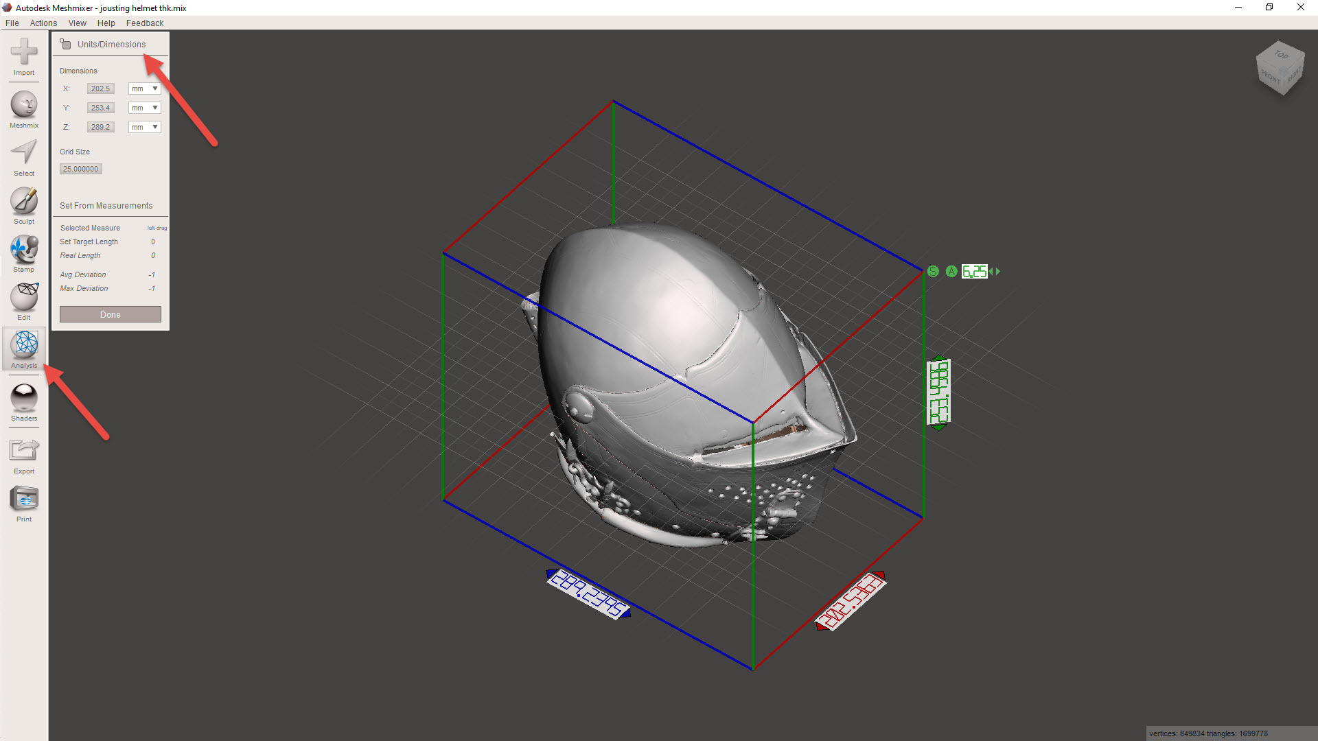
Before we apply a material thickness, we need to be sure the object is correctly sized. First, we need to identify the actual size of the imported model using the INSPECTOR> UNITS/DIMENSION command. Then go to EDIT>TRANFORM to scale the object to the desired size. For this example, I kept the size within the boundary limits of my 3D printer.
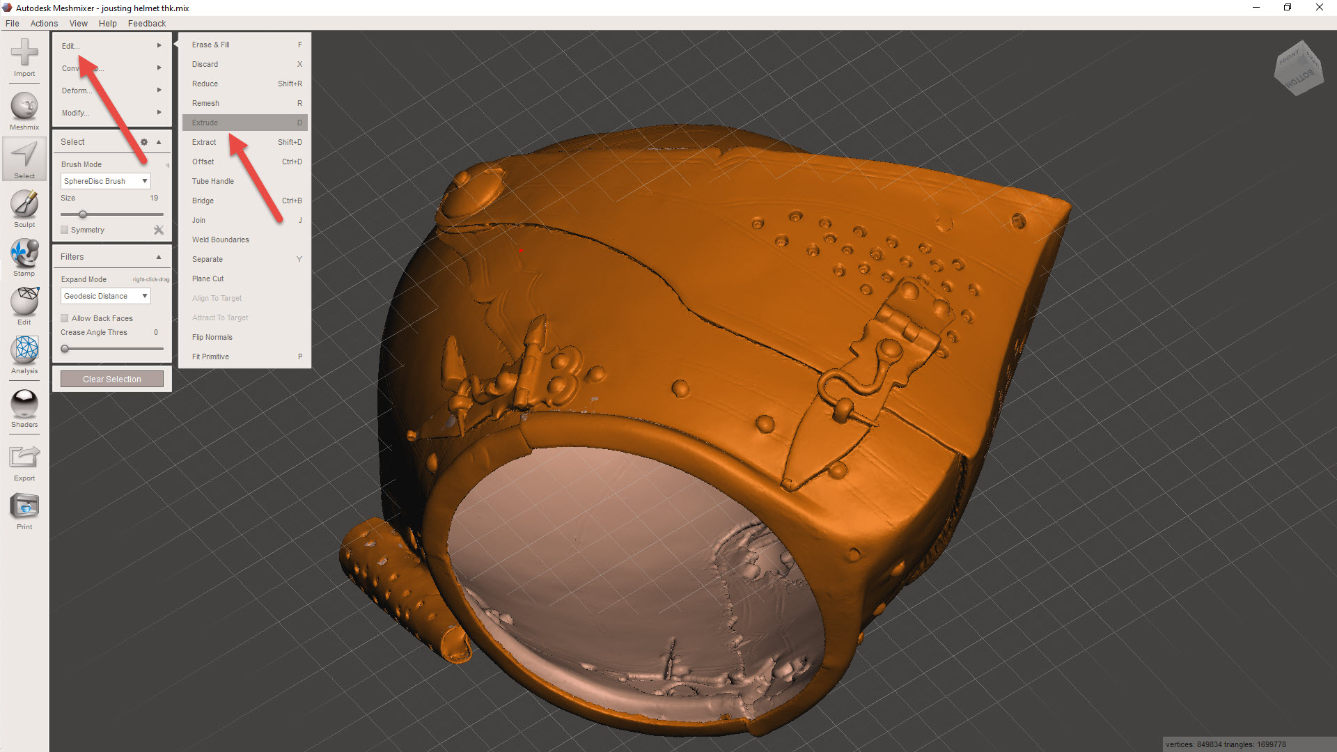
For wall thickening, usually a minimum of 1mm is the recommended value, but for this example, I set it to -0.8mm (twice the nozzle size), and it printed just fine. The thickness is applied using the SELECT>EDIT>EXTRUDE combination, and be sure to select “NORMAL” and “OFFSET”. Don’t go crazy with the wall thickness, as any interior surfaces will thicken accordingly and may exceed the gap between the inside and exterior faces, causing some odd surface anomalies.
Export the model to STL, and it should be ready for 3D printing. Sometimes the walls may be thinner than expected due to the process described, in which case, be sure to have the Thin Walls option selected in the slicer.
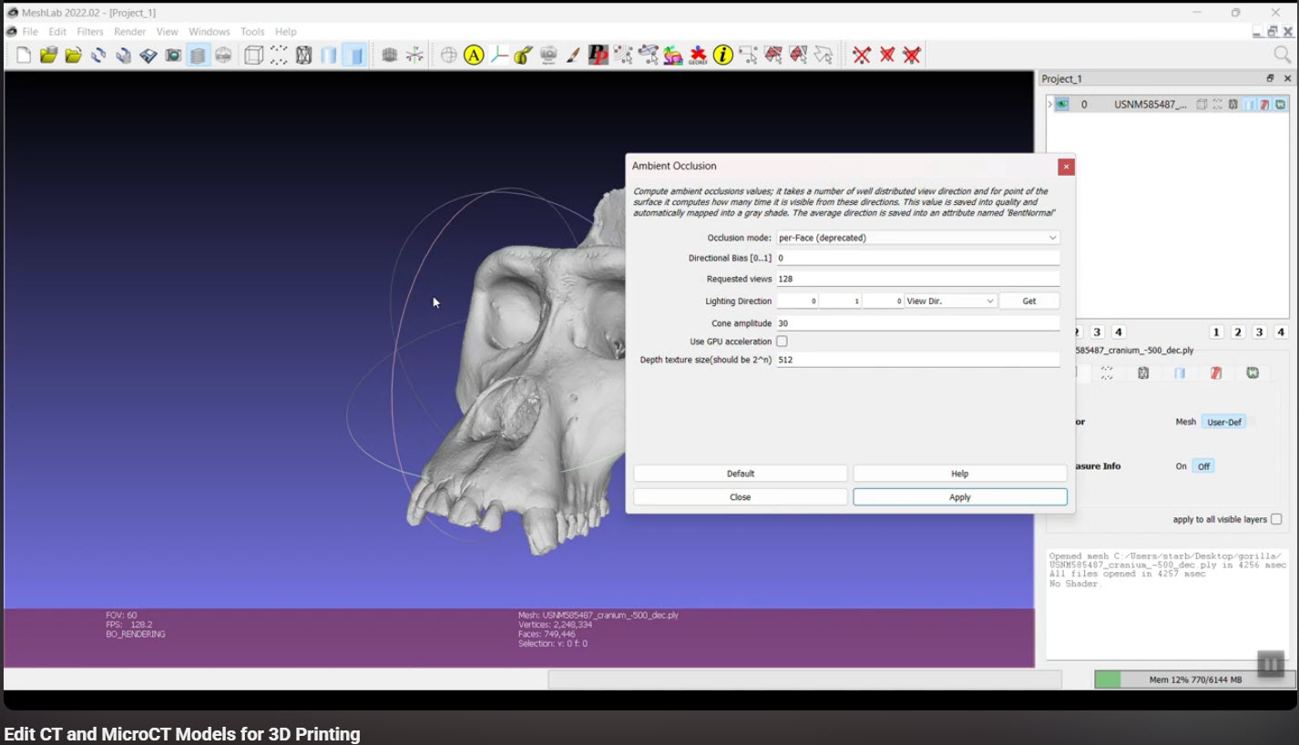
Identifying Interior Meshes:
This may or may not be relevant, but sometimes when tidying up models from a third party, you occasionally find combined models with a lot of interior surfaces. There is an interesting video showing you how to fix this using Ambient Occlusion in Meshlab by Terry Simmons-Ehrhardt
The End Goal:
After creating a tidy meshed model, you can import it into CAD, in my case, this would be Inventor. This model can then be used to generate contours for further CAD development.
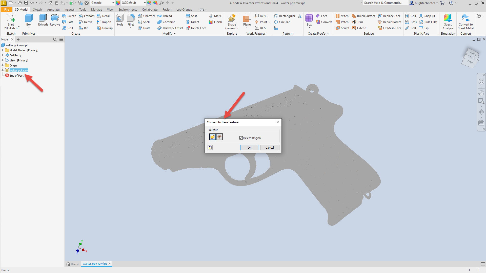
For this example, I have imported the Walter PPK scan. When using Inventor to work with scanned STL or OBJ files, the model must first be converted to workable surfaces or solid models after import. Autodesk Inventor uses a 3rd party add-in called Mesh Enabler, which is availablehere. Fusion also has the capability of working with imported scans, which does not require any special add-ons.
When selecting the type of conversion, always select the Solid option. Even though it may fail to compile a solid first time around, it does give you standard surface meshes to work with. The other option for a composite surface is less workable and occasionally frustrating to work with.
Once you have a solid mass or a workable surface, you can identify key vertices to facilitate contour development for further design.
I chose medieval helmets to illustrate the principles mentioned earlier because they are excellent subjects to practice contour development workflows. They share similarities with aviation subjects and are also engaging to work with.
