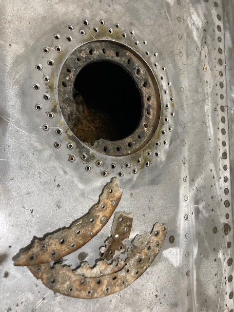
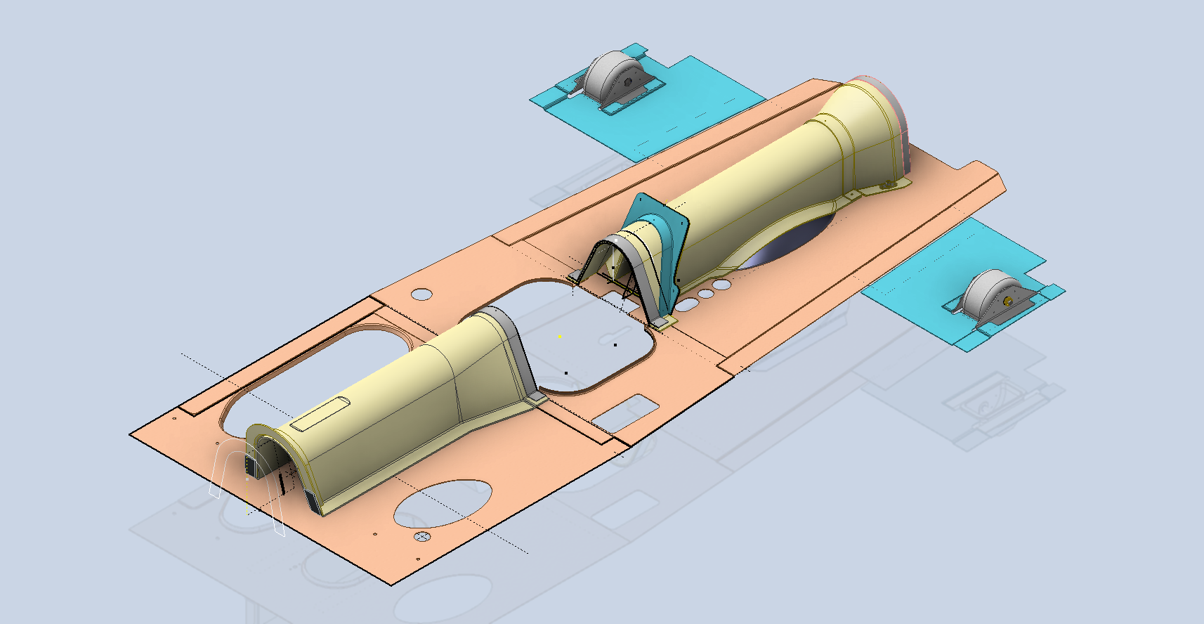
The P-39 restoration project is still very much a work-in-progress. The latest addition to the project is the Fuel Tank Covers and Filler Cap. When the existing components were removed there were visible signs of corrosion so it was decided to replace the inner mounting rings as well as the covers/caps.
Each cap assembly consists of an inner mounting ring, a Goodyear-type sealing ring, and cover plates. It is important to consider the varying thicknesses of the sheet metal at each location, as this can lead to slight differences in the profiles of the mounting rings. Typically, when we develop these types of parts, we mark the holes in situ based on existing hole patterns to ensure a proper fit. This is usually done because the holes are evenly spaced between two known locations, which can vary during manufacturing. However, for these covers and caps, we have precise knowledge of the hole locations, allowing us to ensure an accurate match.
The flush rivets used throughout are the 35R1 Bell standard, featuring a 120-degree countersink designed for thin sheet materials. An equivalent Boeing standard for this type of rivet is also available. In the assembly drawings, I have spaced the components apart to enhance clarity. I should note that the drawings shown are still a work in progress.
Update: Ready for issue:
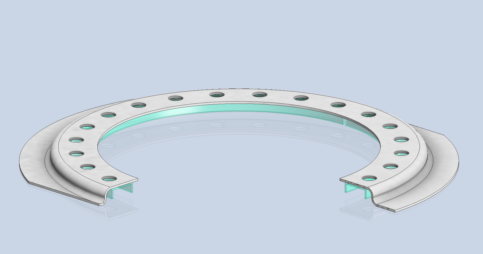
This is the final assembly, typical for the fuel tank covers and caps.
The lower ring features an Elastic Stop Nut Gang Channel. It is presumed that this channel was designed according to Bell standards when it was constructed. I have examined various companies that supply similar Gang Channels; however, the hole centers in their standard components differ slightly from our specifications. I suspect that we will need to have a bespoke fabricated item to meet our requirements.
It may be possible to purchase Elastic Stop Nuts and retaining springs from companies like Howmet Aerospace and create a channel to match the design in the second image below. I will provide an update later on how we will proceed.
I will also soon be able to provide you with more information about the P-39 restoration and a gallery of images showcasing the latest work.
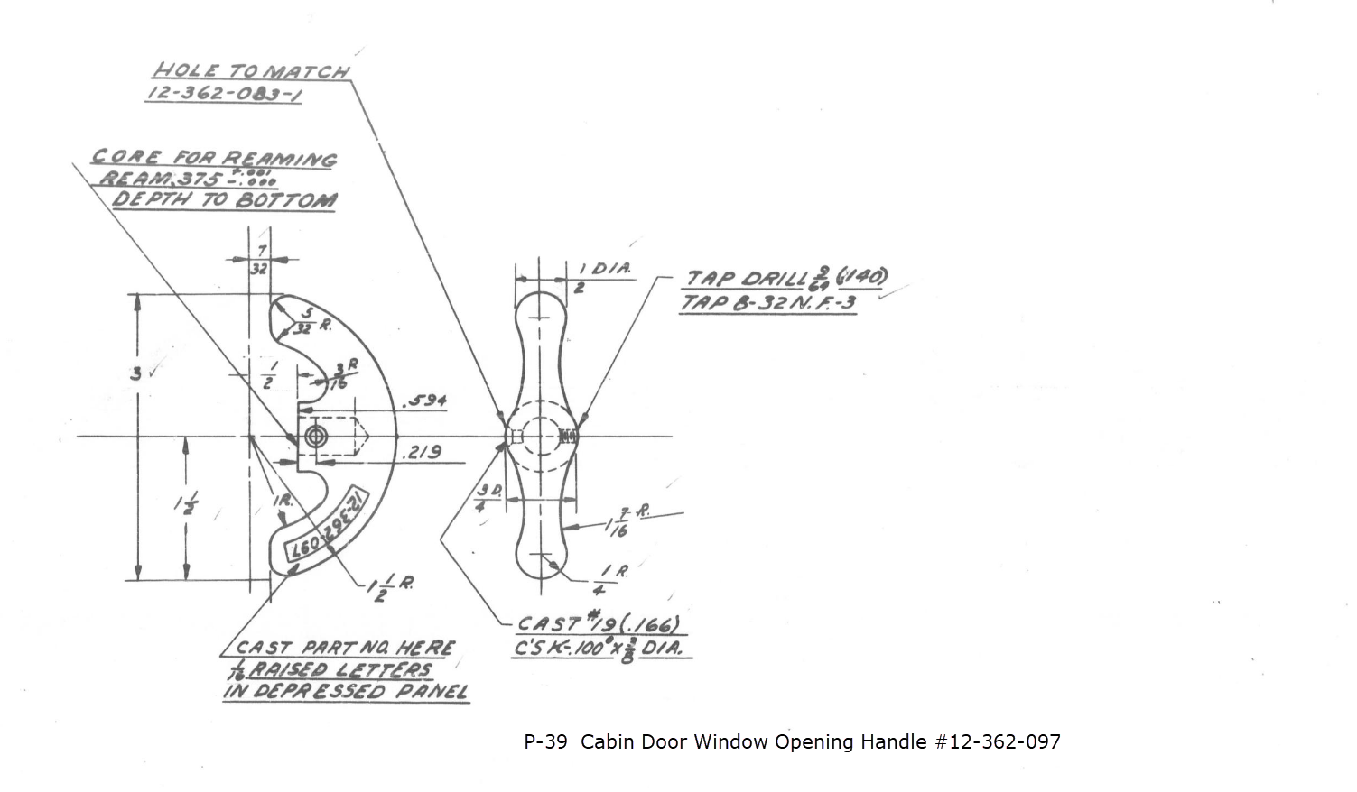
This little part at first glance seems fairly straightforward, but there are a few caveats.
It has been a while since I specifically wrote a CAD solution Technote, and this seemed to be an ideal subject for surface modeling and 3D sketching. The dimensions define the outline for the front view, which is fine, and the plan view, which details a thinning of the handle cross section.
The thinning of the handle occurs in a specific plane as indicated in the plan view, while the front view maintains a consistent full depth diameter. Before diving into the modeling process, it’s important to pause and consider how to approach this design. Typically, my first step involves sketching out what is already known, which helps clarify the information we still need to gather. This initial sketching phase is crucial for laying the groundwork for an effective modeling strategy.
In each case, you’ll notice that these profiles are not closed. The base lines shown in the front view are defined as construction lines, and the end curves in the plan view are also intentional. This design choice allows the main profile lines to be used later for creating a Loft and for selecting a 3D Sketch Intersection. The center line of the arc in the front view will serve as the second selection for this 3D sketch. Additionally, note that the curves in the plan view are elliptical.
The purpose of the 3D Intersection sketch is to define guidelines for the eventual loft. Using the 3D sketch feature, we first select the center line from the front view and one curved edge from the plan view sketch. The resulting intersection will serve as the 3D path for the loft. This process needs to be repeated for both sides of the handle. The ellipses that will form the ends of the loft are created in a separate sketch from the previously mentioned plan view. This keeps them as distinct entities.
Hold on a moment; where did the ellipse in the middle of the arch come from? If we simply loft the two end profiles of the arch, as shown earlier, we can create an acceptable model, but it won’t be ideal. In the second image, where both surfaces are overlaid, you can see that this approach tends to create a diamond-like cross-section in the center. While this is not entirely incorrect, incorporating the ellipse in the center of the arch results in a much better finished surface, ensuring good continuity, as demonstrated.
Once we have the arch lofted surface, we extrude the centre section circle to match the surface contours.
We then use this extrusion to trim the underside of the arch surface, apply patch surfaces to fill in the ends of the arch and this centre section. Then stitch everything together and we have the main solid model.
Apply a fillet as shown to the underside; note the fillet in this case is better selected as a tangent fillet and not a G2 curvature. It is often tempting to overuse the G2 fillet option as the perceived notion is that it creates a smoother finish, which by the way is correct, though in a case like this it tends to sharpen the fillet corners which is not good. Something to watch out for when applying fillets.
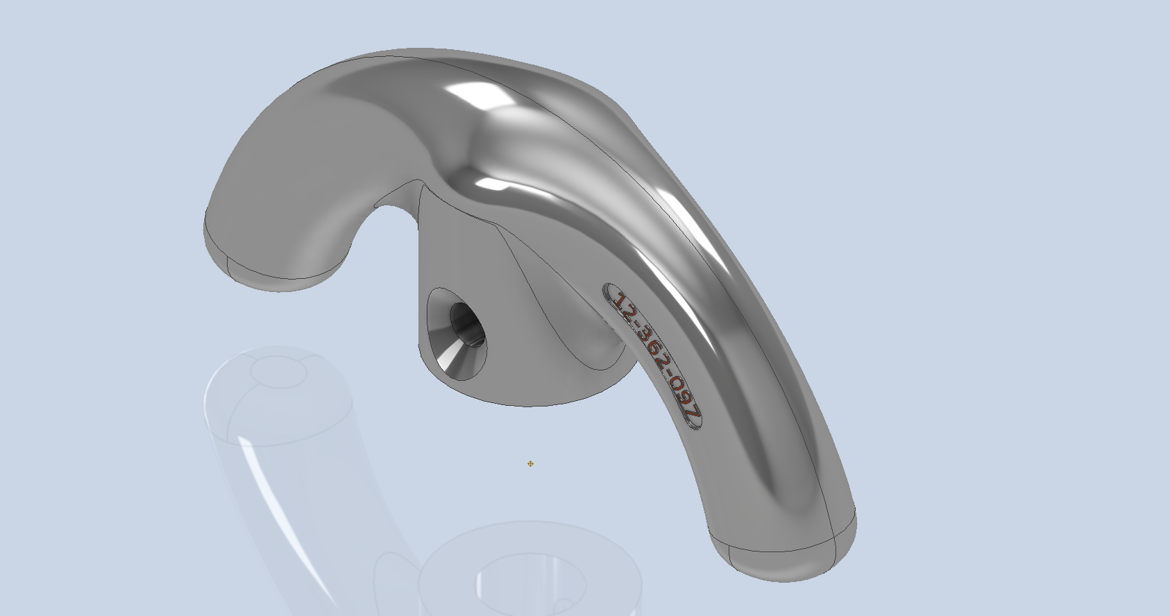
To finish up we add the holes as specified, fillet the ends of the arch (a good opportunity for a G2 fillet) and add the part identifier. The final part should look something like this:
In summary, when developing surface models, it’s beneficial to explore your options and start by creating sketches that support your plan of action. Consider using 3D intersections to define loft paths, and incorporate additional geometry as needed to maintain the circularity and continuity of the final surface.
This part is ready for manufacturing, which will probably be 3D printed for this static display restoration.
Typical Design Workflow:
Usually I would initially receive an inquiry via email from companies like Planes of Fame for a 3D CAD model of a specific part or assembly. Typically, the request includes a brief description of what is needed and not necessarily the actual part number. In this instance, it was for “the handle for operating the window glass.” I then searched through my archives to locate this item, reviewed the part’s blueprint, and checked which parts or assemblies it connects to ensure I have all the relevant information.
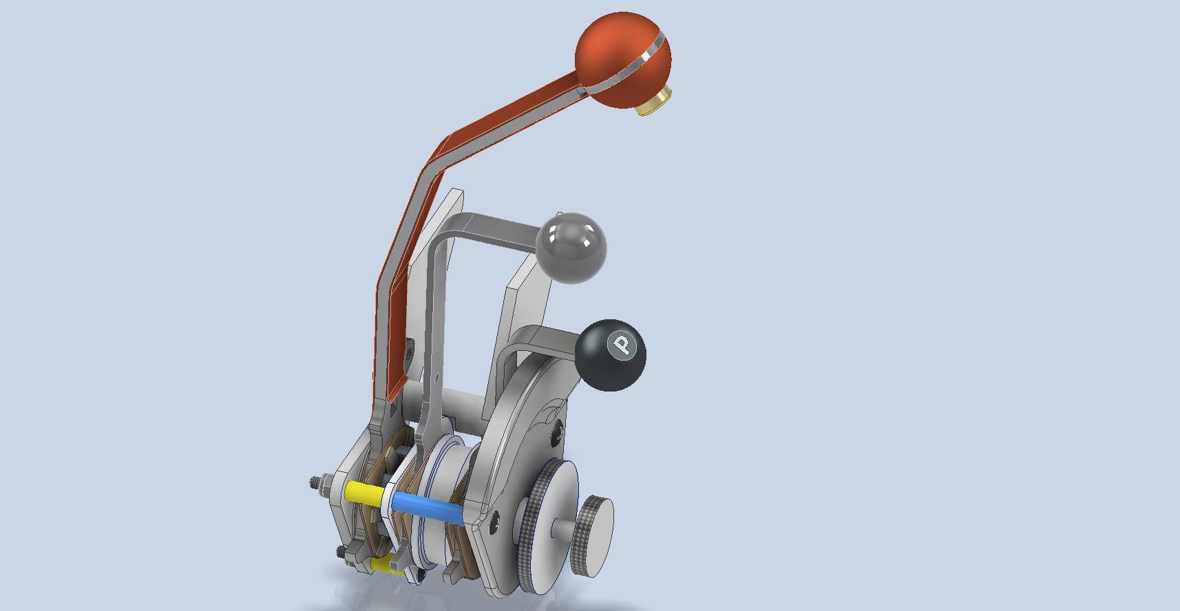
I will make every effort to start working on the CAD model as soon as possible, regardless of the time of day, to minimize any delays. For example, I received an inquiry about a part at 9:17 PM last night for the “P-39 Throttle Control Mount.” Following the established procedure, I was able to begin working on it relatively quickly on a Friday evening. The finished part (#12-631-027) was completed and submitted on Saturday at 11:17 AM. The final design included both the original 3D CAD model and a fully dimensioned 2D drawing, which is essential for verifying that all dimensions conform to the original blueprint.
This part will likely be 3D printed for the restoration of the static display, so the 2D drawing serves both as a dimensional check and a reference for manufacturing. If the inquiry had required a metal casting manufacturing process, the drawing would include more detailed information about part machining and the tolerances necessary for a full-metal manufactured item.
If you’re looking to bring your ideas to life with accurate 3D and 2D CAD models for replica parts, I would love to help! Don’t hesitate to get in touch hughtechnotes@gmail.com
During the development cycle of any aircraft the manufacturing standards tend to evolve and commonly change content, description and name. Keeping track of those changes is key to ensuring the defined parts are correct for the assembly of components.
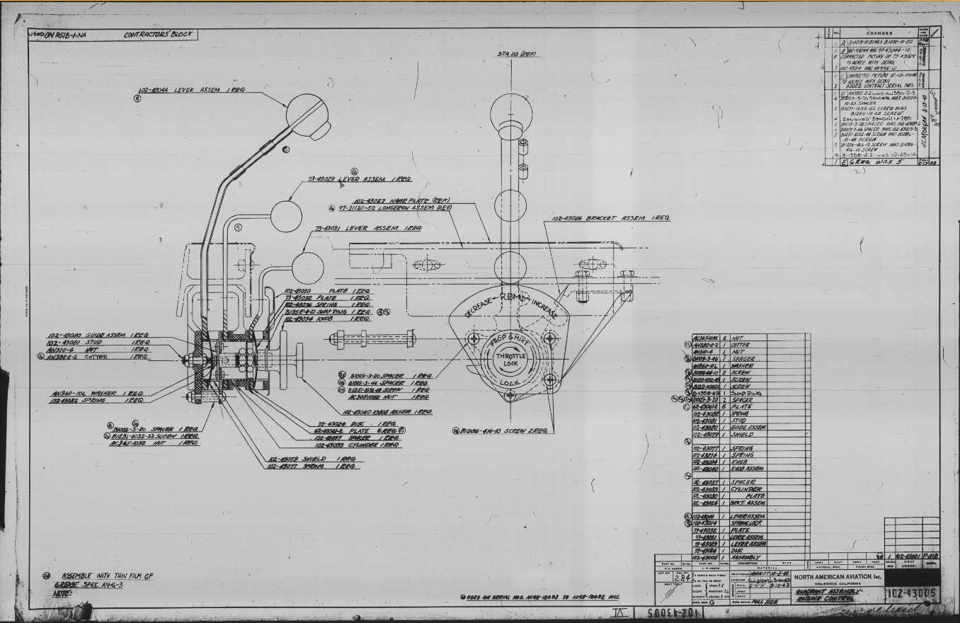
Alongside the P-39 Restoration project, I still develop several aircraft components for other aircraft. This includes my old favourite, the P-51 Mustang. This example refers to the Quadrant Assembly for Engine Control; drawing #102-43005 for the early P-51B.
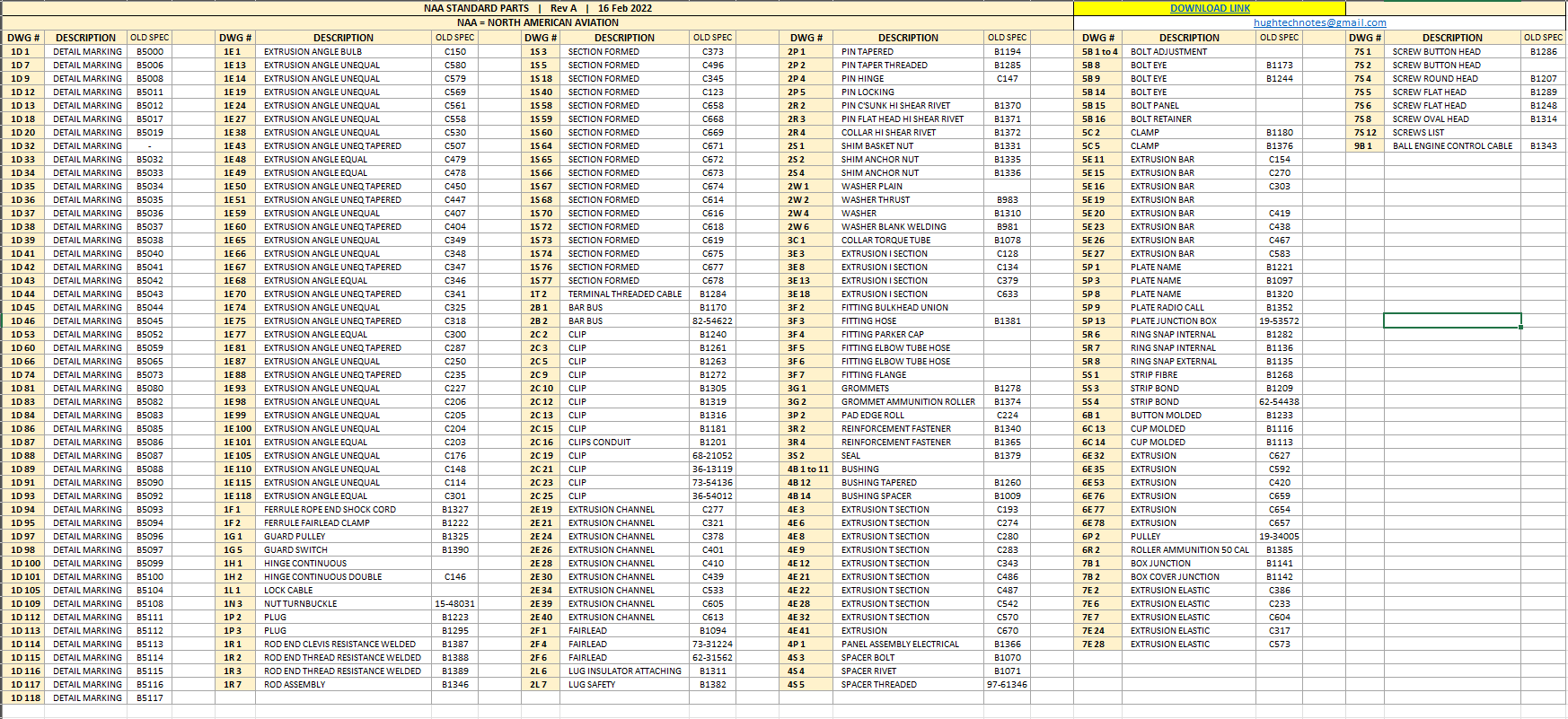
Many of the standard parts called up on this assembly use the early standard references. These are typically prefixed with “B”, like B1009, B1135, etc. These standards were later updated, and a new series of standards replaced them. I have correlated these in a spreadsheet, as shown below.
The spreadsheet only lists the standards that are available in the blueprint archive and may not be a complete record. For a more comprehensive listing, refer to the Erection and Maintenance instructions for the P-51A series (T.O. No. 01-60JC-2). Check the Conversion lists from pages 404 onward.
The CAD development of the Quadrant Engine Control is still a work in progress…created to the exact original dimensions.
My plan for the P-51 is to further develop the instrumentation for the early and later versions.
P-39 Update and Standards:
Over the last few months, the P-39N Restoration project has been my primary focus. We are close to completing the CAD work for the Cockpit instrumentation.
By contrast to the P-51 Mustang, we don’t have the same collection of Bell Standard part blueprints. We only have what is available within the manuals. However, the notations for the parts are similar for the industry as a whole. For example, a Spacer Part noted as Q065-6-20 shares the same notation for the dash numbers as the P-51 (standards 4s3 and 4S4). This in turn will define the spacer size…the first dash number sequence indicates the bolt size and the second is the length. In this case, it would be #6 bolt size. The length is defined in 1/32nd inch, making it 20/32″ (5/8″) long. This table derived from the iPart feature explains the designations in more detail.
The next time you come across a part reference you are unsure about, cross-reference it with other aircraft-known standards. Also, consult the comprehensive collection of AN and MS standards on Everyspec.com.
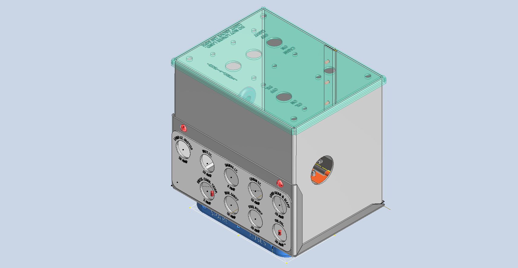
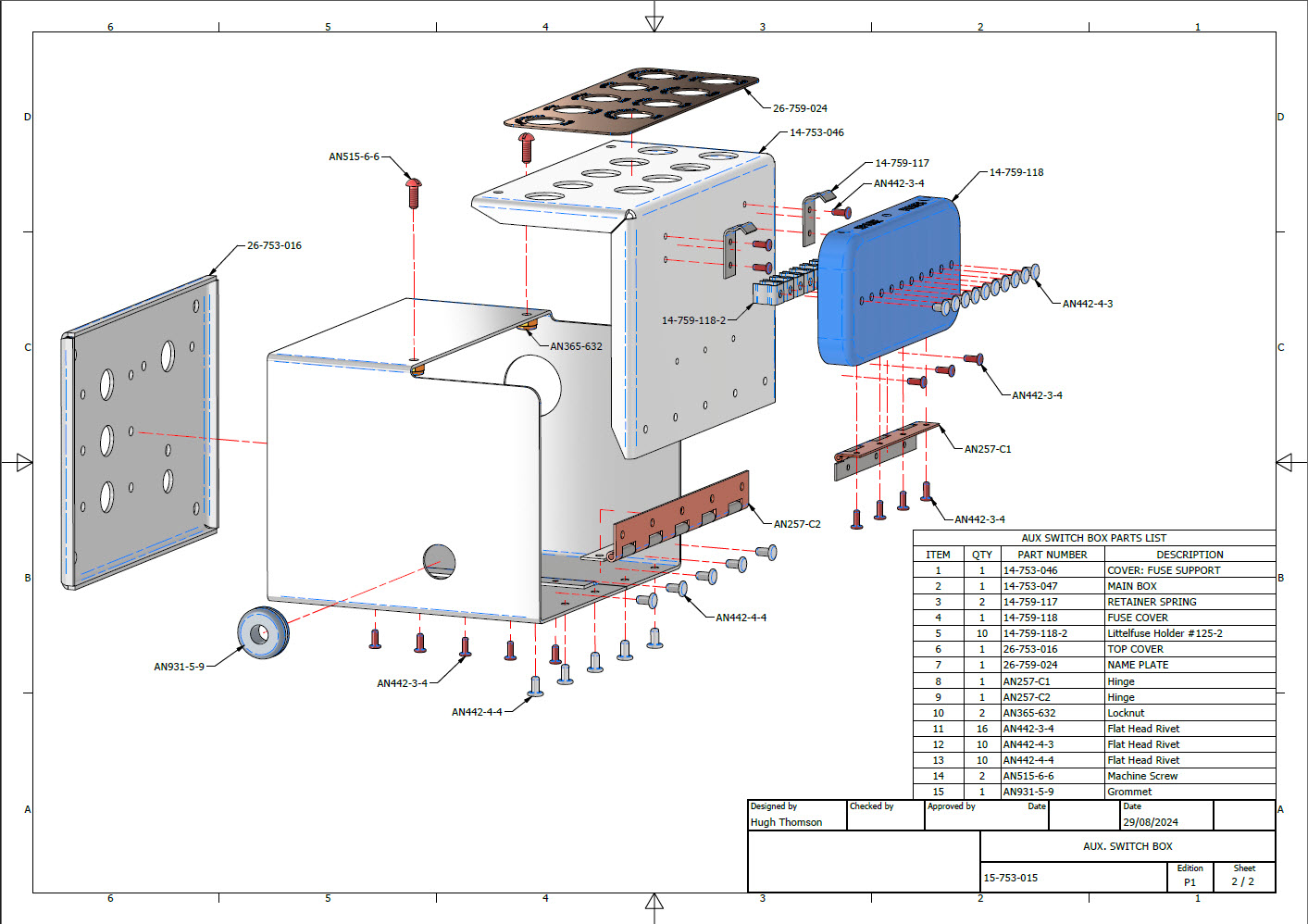
A quick update on progress with the P-39 Restoration CAD work. The final CAD models and accompanying 2D manufacturing drawings were issued this week for the Radio Console…so hopefully that will be built soon and I can share some of the installation photos when that is done. The exploded views as shown are the cover sheets for each assembly. Every part is fully dimensioned and detailed on separate sheets.
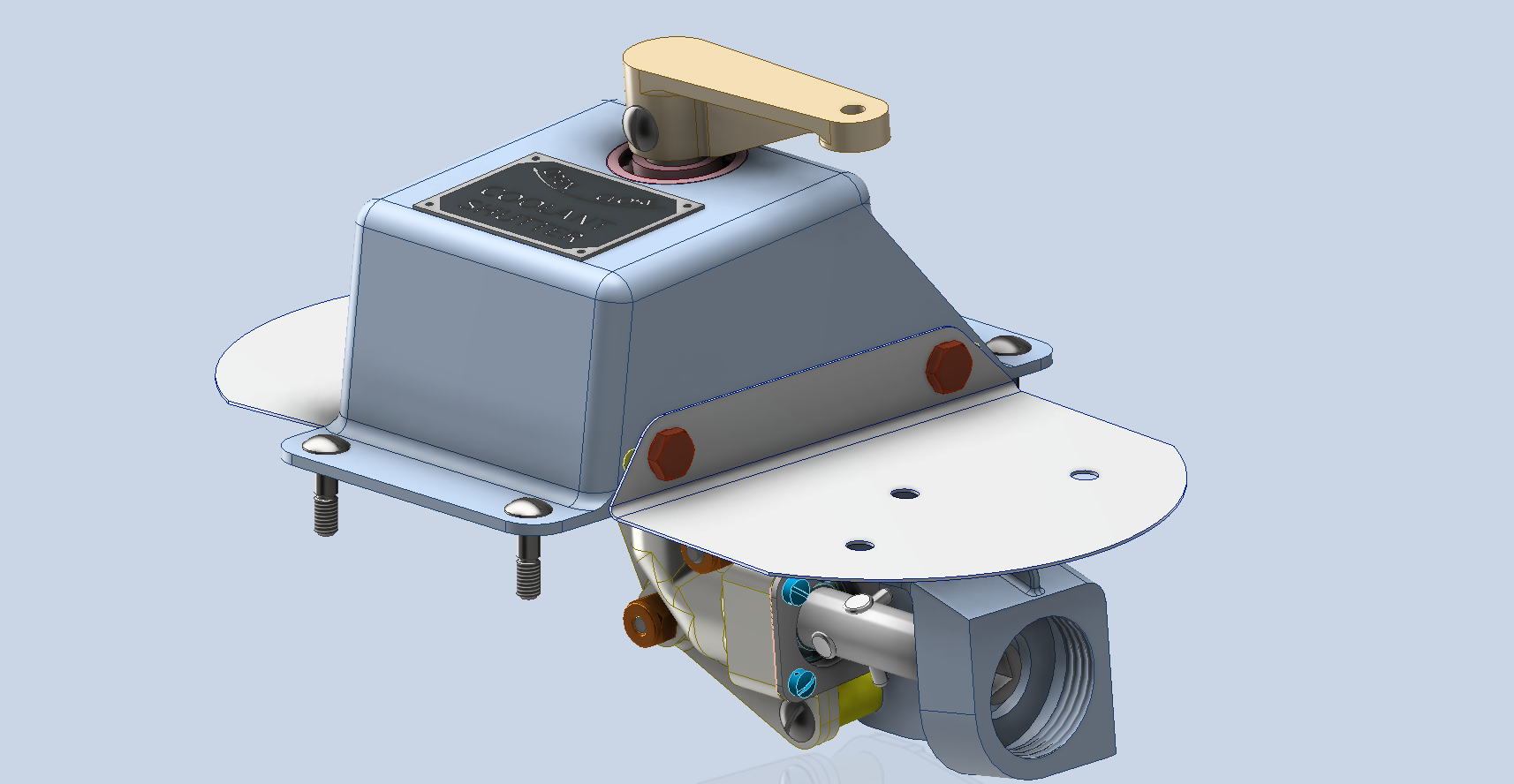
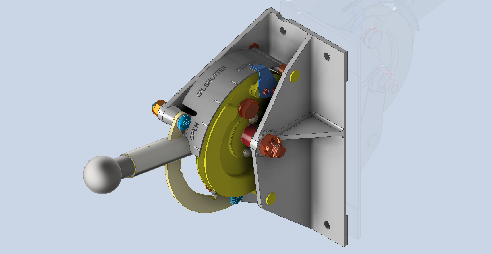
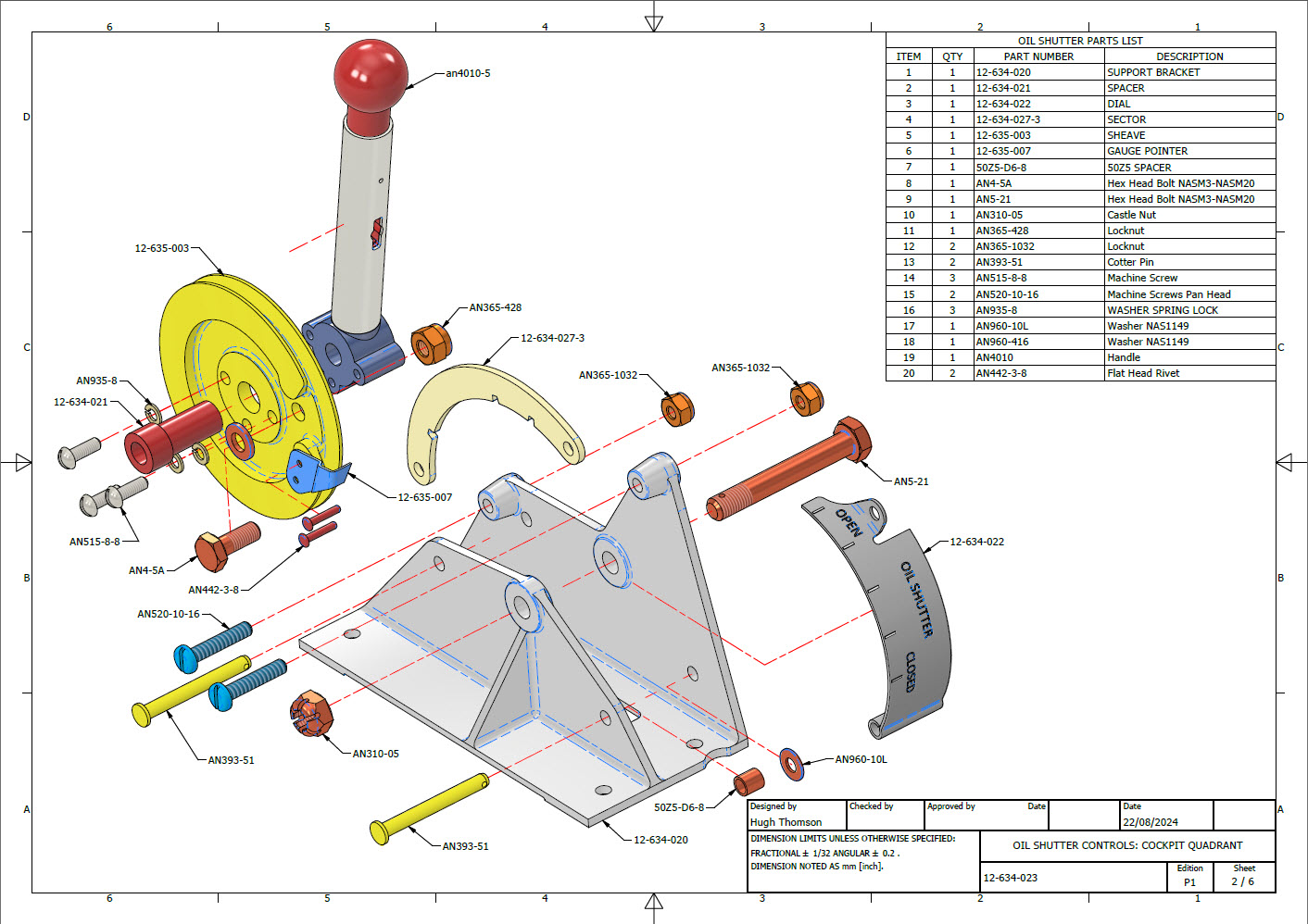
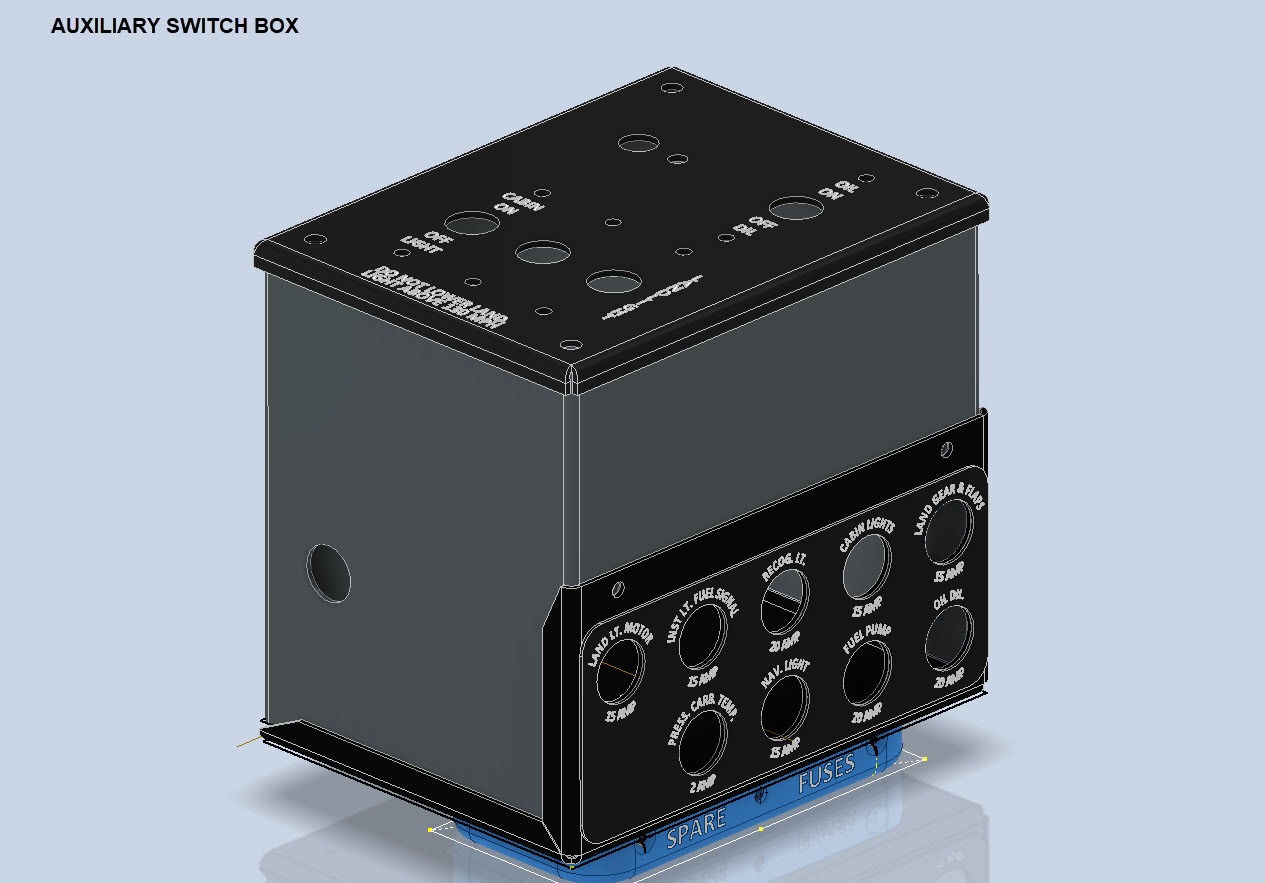
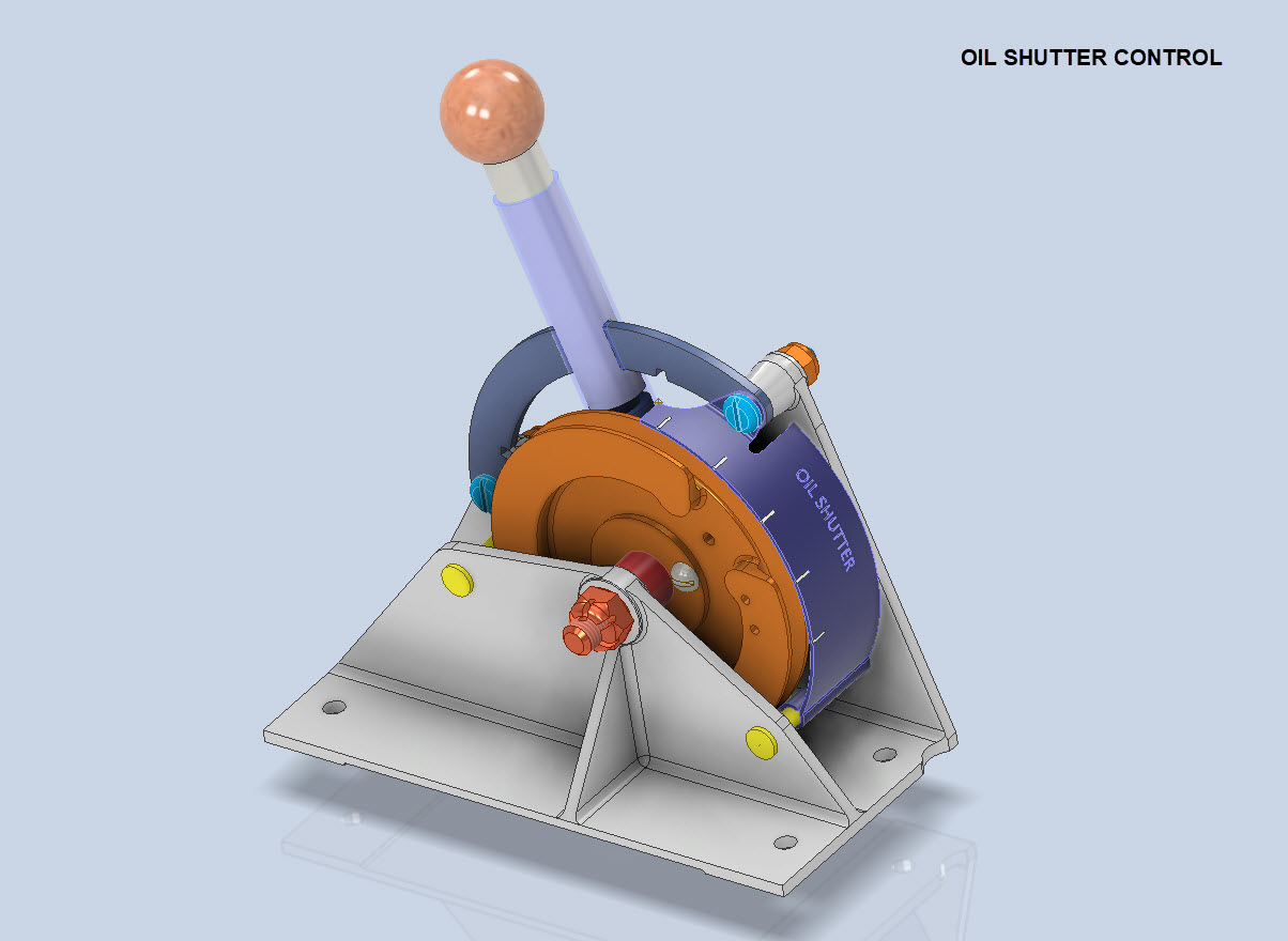
In addition, the Oil Shutter and the Auxiliary Switch Box are well-advanced in the CAD development stage. These are currently in abeyance while we check the availability of some of the components.
To compliment the Oil Shutter and Aux Switch Box CAD work I have also developed a few basic component assembly videos that are now on YouTube.
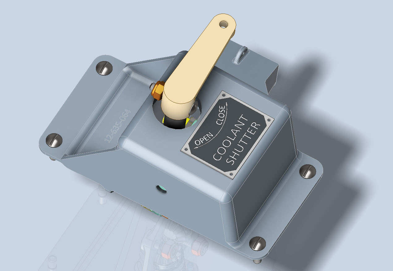
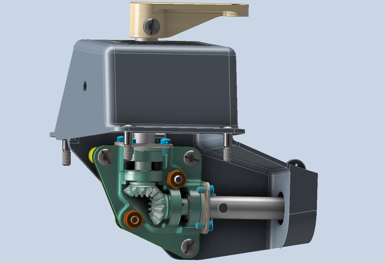
Have now almost completed the Coolant Shutter CAD model for the P-39. All bolts, rivets, nuts and screws are modelled to exact AN and MS standards. Hopefully, in the next week or so I will do an assembly video and upload that to YouTube…so stay tuned for more updates.
A quick note on relevant standards for bearings. The Bell drawings typically refer to type “K6A” or “K8A” which is equivalent to the AN201 standard (not the AN200 that refers to types KR6 and KR8). The AN201 standard was replaced by the MS27641, which in turn was cancelled in 1995 and replaced by SAE-AS27641 (dated 1998).
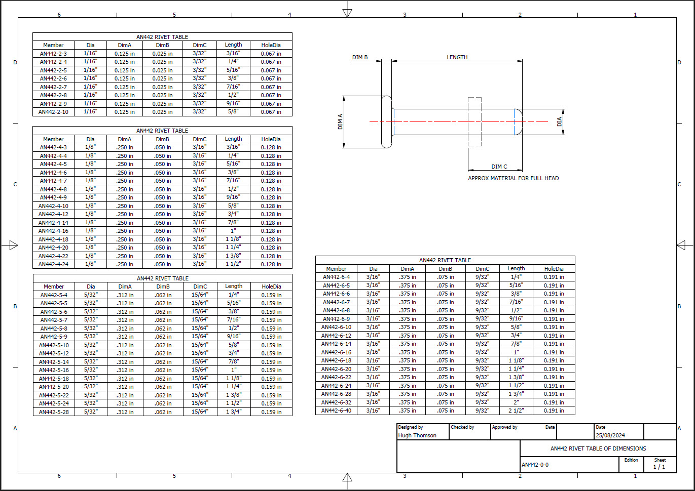
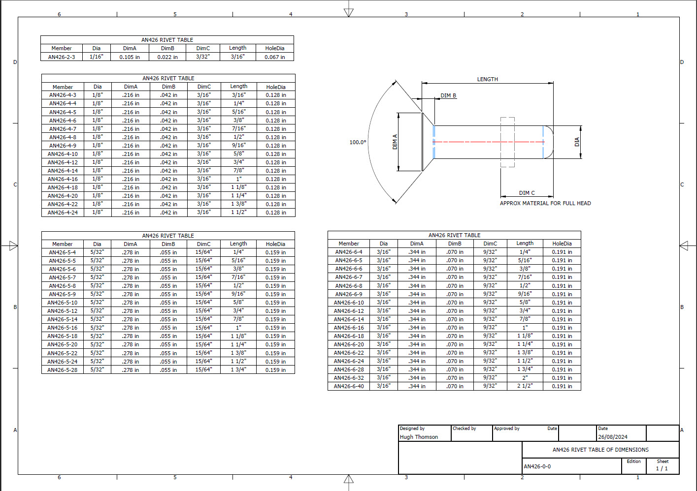
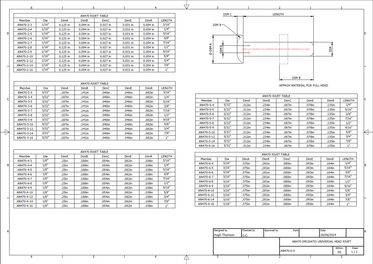
Developing the CAD standards for Rivets has been on my to-do list for far too long..so with the progression of the P-39 cockpit instruments it has become a priority. Typically on the Bell drawings and other aircraft manufacturers’ drawings we may only have the hole sizes noted, the rivet designation or information pertaining to the same but unreadable. Also occasionally even when we do have the hole sizes and the rivet designation often we don’t have the length required.
Something needed to be done to make this task a lot easier, particularly when you have instrument panels that incorporate many different types and sizes of rivets.
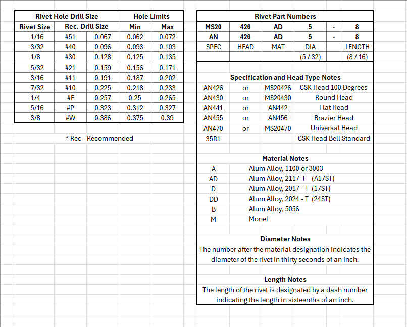
The first part of the process is to create several parts for the various types of rivets; which at the moment are listing the most common sizes I need right now. You will notice that the Rivet Name does not include the material type as doing so would require an extraordinarily large table of data. So the name is simplified to make this task easier to correlate but also because the priority at this time is dimensional correctness for rivet type, diameter, hole sizes and rivet length. At some stage, I will invest some time into deriving the various information sources to correctly name the rivets according to the AN and MS standards.
To complement the CAD iParts I also have a few spreadsheets listing key parameters and fabrication criteria.
The above tables are self-explanatory with the inclusion of a designation for a Bell Standard Rivet 35R1. I have actually found dimensional information for this type which I will include in the CAD library. This is where things get interesting because of the scarcity of historical components that may no longer be available, it may be necessary to find suitable alternatives.
You will notice that the Rivet Grip tables are in inches and mm…as I tend to work using metric mm templates (although the dimensions are input as inches) it makes it easier to measure the material thicknesses in mm and determine from that the rivet length. There is a technote somewhere on my blog that describes the process of inputting inch dimensions in metric mm templated models.
This will be an invaluable asset moving forward with the cockpit rebuild on the P-39. For example where there are issues with the legibility of key information on the Bell assembly drawings I can refer to other connecting part drawings that may only have hole diameters but will be sufficient to determine the correct rivet type and size.
This is very much a work in progress and will be updated as needed.
Update: 28th August 2024:
I have updated the Rivet CAD files which now include AN426, AN430, AN442, AN470 and of course the Bell standard 35R1.
All Rivet CAD data files (iParts) are now included in the CAD Standard library (see CAD resource tab for further details) along with original spreadsheets of Rivet Grip and general details.
The P-39 Restoration project was rather busy last month. The chaps at PoF have completed and test-fitted the Drive Shaft Cover fabrication and the Floor panels for the Rudder Quadrant…all is good. The Radio Console is now designed with the 3D CAD models and fully dimensioned 2D drawings; for all parts; issued for fabrication…I am looking forward to seeing the finished product.
Several other components are still works in progress with the CAD development well-advanced. These are for the Auxiliary Switch Box and the Oil Shutter Control. I still have the detailed drawings to do for both of these assemblies, which hopefully I will get done in the next few weeks.
Today the importance of fully dimensioned and detailed 2D drawings is commonly overlooked. It is an essential part of the process to both check dimensional accuracy and also to ensure that the clearances and fabrication tolerances are correct. So I tend to do 2D dimensioned drawings for everything, even items we know in advance that will be 3D printed. All the assemblies include all the necessary bolts, nuts, screws, washers and other standard components in compliance with the requisite AN and MS standards.
As you know I already have a fairly comprehensive library of over 350 parts parametrically modelled in CAD, which although comprehensive will at some stage require the addition of more components as highlighted by this particular project.
The current library is available on the CAD resources page, which will save you a lot of time and effort on your own projects. Although these CAD files are aimed at Inventor users you can quickly download an evaluation copy of Inventor from the Autodesk website and convert them to any CAD format you need.
Please consider making a small donation, even the cost of a coffee will help support my work on this project and the research work on other aircraft.
As usual any comments or feedback please drop me a line at hughtechnotes@gmail.com
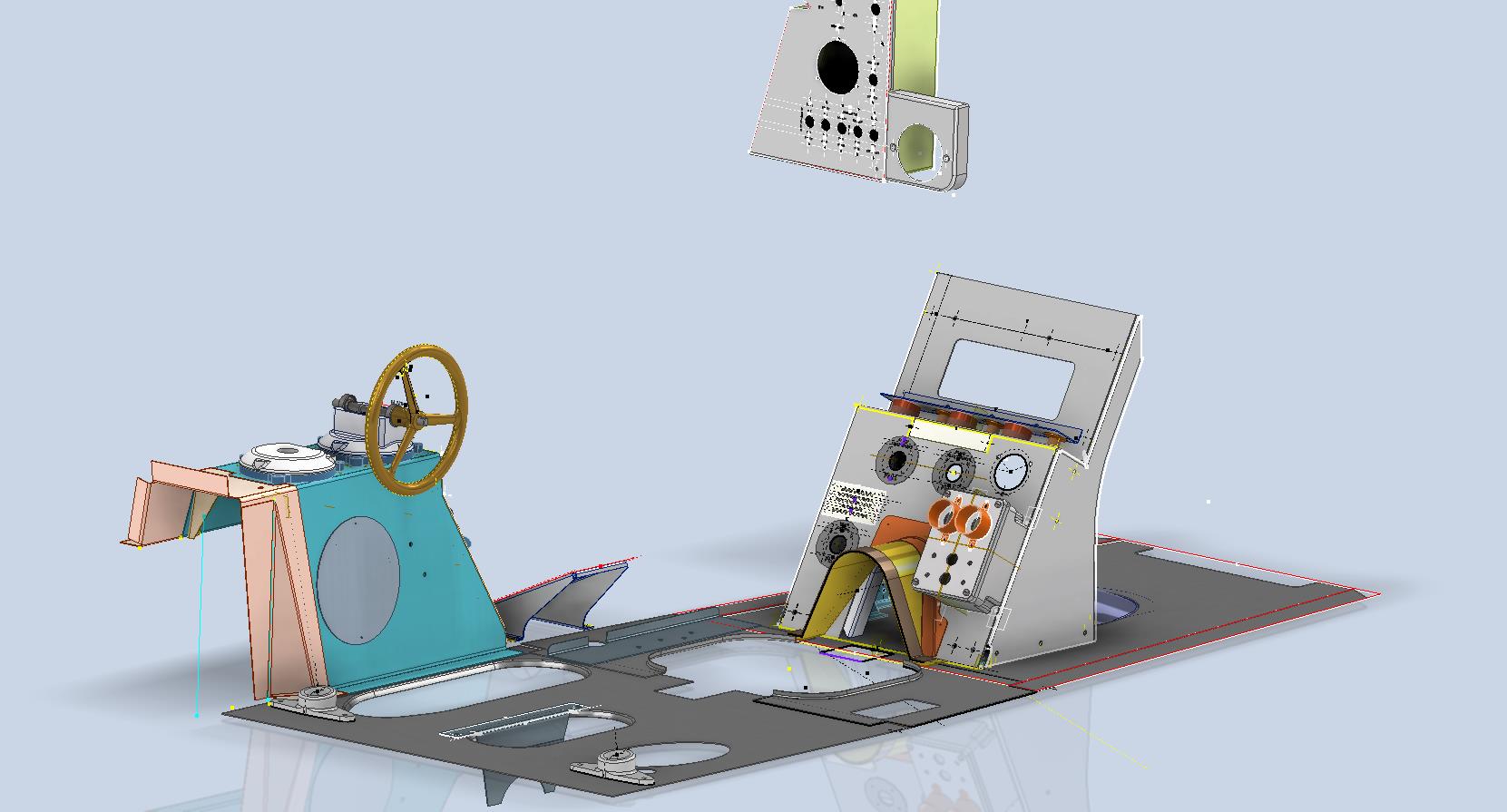
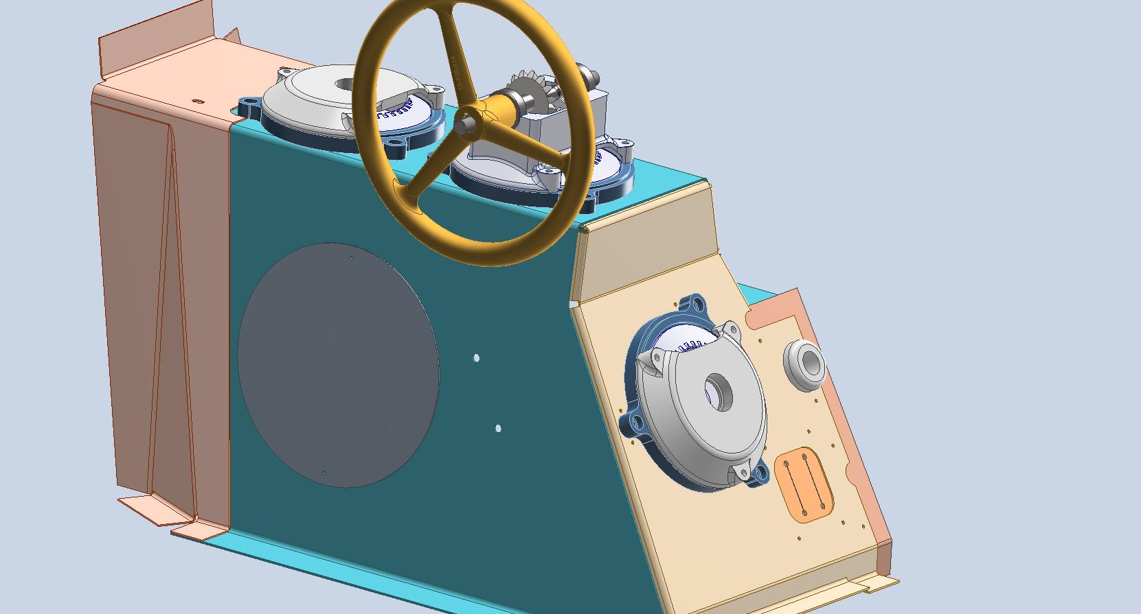
The FM2 project has been parked for a while as we must focus on the P-39 Airacobra Restoration project. The work has shifted to the Cockpit where we will literally be building a new cockpit from scratch. This is a lot more work than we initially envisaged, but ensuring we get this right is necessary.
Let me take you through some of the work involved in this process and what I did to circumvent areas where little or no information was available.
So far we have the Trim Tab Control, the Switch Box and the Centre Radio Console. The Switch Box and the Trim Tab Control have already been fabricated and test-fitted. It is very important to check the fabrication before the final installation as there is likely to be some variation in the actual versus the perceived location of structural elements. Normally I also provide additional templates to help with this process.
The Radio Console is one area where I had to do a lot of research and development work due to the lack of specific Bell drawings for the main panel. Trying to layout a panel correctly can be quite difficult when the panel drawing is not available so you have to innovate solutions from known information for the P-39C, C, D and F variants. I forgot to mention this restoration project is for the P-39N.
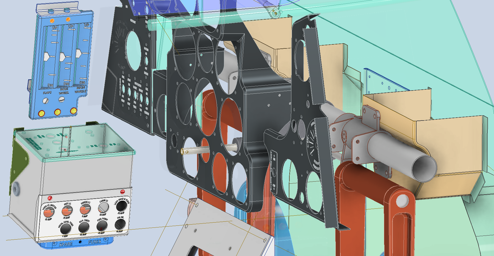
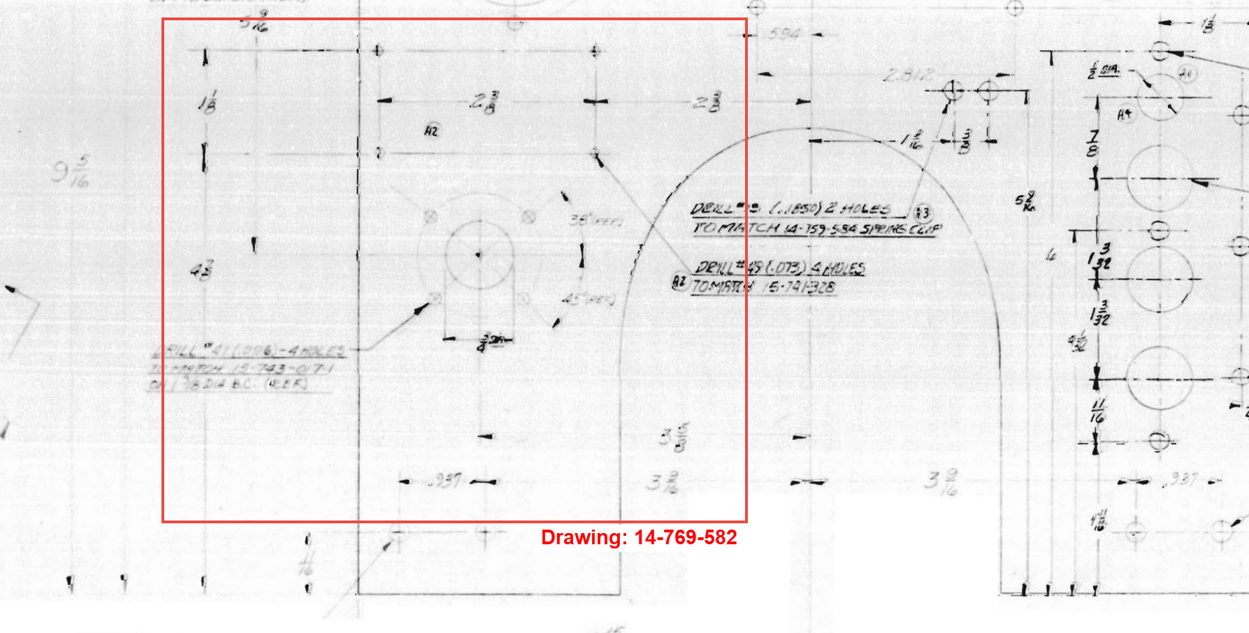
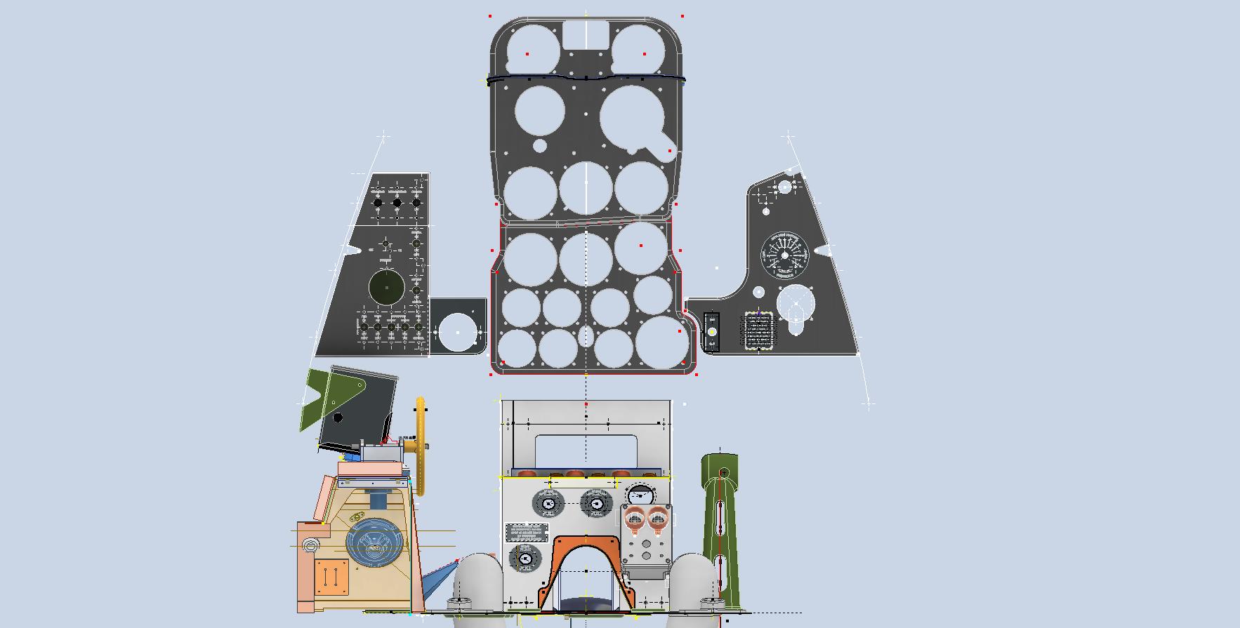
The process involves reviewing all existing resources including blueprints and manuals for all the other variants and extrapolating useful information to establish a viable layout for our P-39N. The first image above is a partial view from Drawing 12-769-011 (P-39C, D, F) which shows the location of the Radio Switch box, the same as required for the P-39N. The Switch box itself is a supplier component for which we don’t have the specific dimensions however, we do have the Name Plate which was used to determine the actual box dimensions. The second image is the location of the Bomb Release from Drawing 14-769-582 (P-39D-2) similar to the requirements for our P-39N. The third image is the 37mm Gun Charger and Loader.
Often when there are updates and changes to instrumentation panels it is common to reuse existing references where possible to simplify change. In the case of the Gun Loader Charger, the centre-to-centre distance of these controls is paramount as defined in Drawing 15-769-017 (P-39D) and replicated in later versions. Collectively we now have pertinent information that in combination will give us the information needed to lay out that actual panel for the P-39N. Still, some finishing work to do on this and I am satisfied this is a good solution.
You will notice that I have modelled in the floor plates which was necessary to help check instrument locations. Sometimes you may have to actually model the cable routings, floor penetrations and the power conduits to check termination locations which in turn checks instrument positions. Fortunately for this restoration, the majority of the floor plates are reusable except for the Aft plate which will need to be replaced…a temporary plate is currently installed for safety reasons.
Often with a little bit of research most problems where drawings are not available or in some cases illegible can be overcome and it helps to have some background knowledge of how the design process actually works and how key information is retained throughout the development of new variants.
In most cases, research is the key to achieving solutions; take time to review existing materials and not just drawings but also manuals and occasionally correspondence to find relative data that will assist with your goals. Often engineers will trace outlines and profiles from scanned blueprints which in my opinion is not good practice when a little research and time will achieve more accurate and professional results.
Update 10th May 2024:
A few images that show the latest update for the P-39N Cabin model.