Technote: P-47 Cowl Ordinates:
The Ordinates for the P-47 Cowl are listed on Republic Drawing #89P63300 for P-47B, C and D. They differ from the usual ordinate dimensions that usually comprise X and Y coordinates in that they are radial ordinates. Essentially dimensions along a radial axis that are subdivided in 10-degree increments from 0 degrees to 180 degrees.
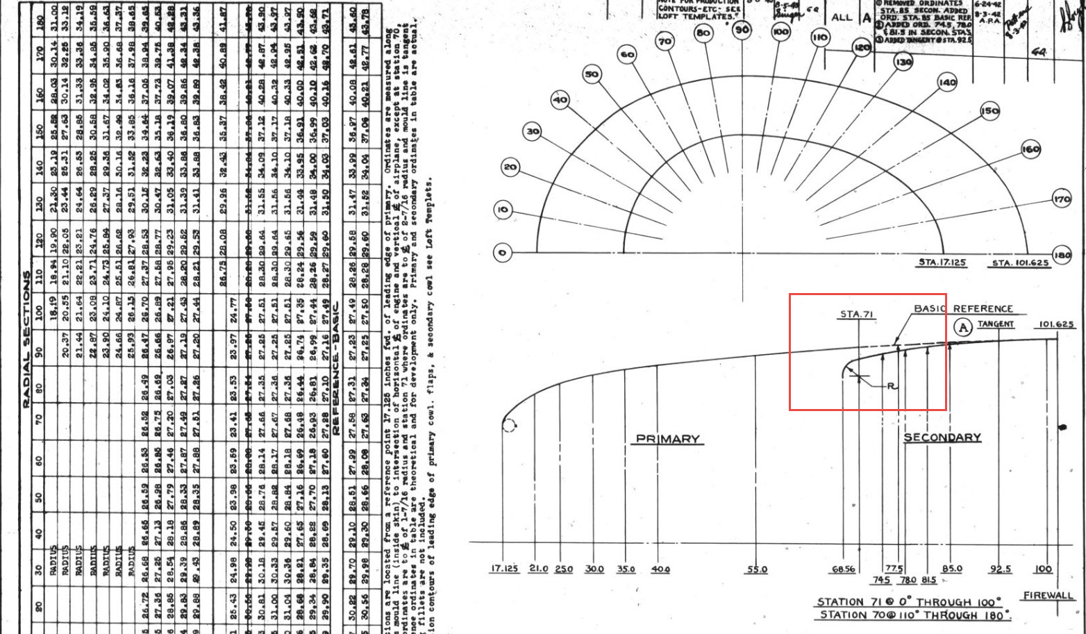

The ordinates as usual are extrapolated to a spreadsheets where I have also converted the radial ordinates into X,Y coordinates should this be required. The highlighted dimensions are the points on the inside face of the cowl skin. The dimensions at Stations 70 and 71, bordered in red, are to the centre of the secondary cowl leading edge radius at each degree increment. To be precise this is actually the profile for the Preheater.
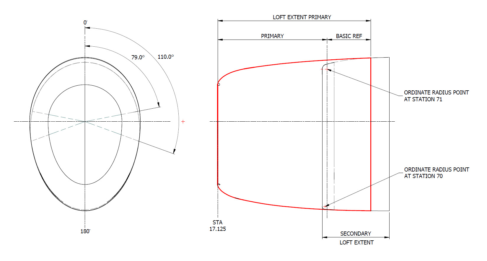
The edge radius at the top of the Preheater is 2 7/16″ at Station 71 and 1 7/16″ at Station 70. On the Republic blueprint the radius of 2 7/16″ is applicable from 0 degrees to 100 degrees, and the radius of 1 7/16 ” is applicable from 110 degrees to 180 degrees. In the CAD drawing above, I have noted 79-degree and 110-degree intervals, and there is a reason for this.
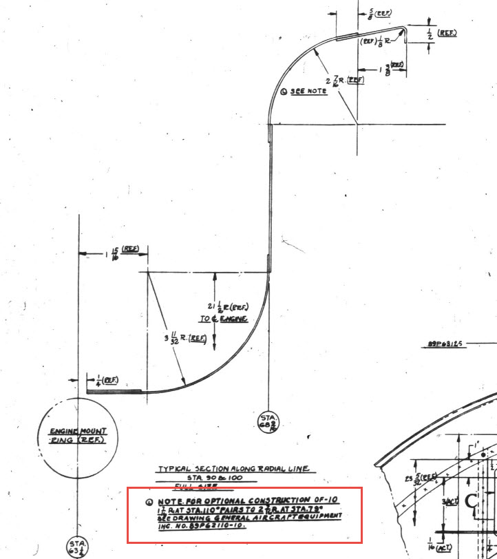
At some point along this Preheater front edge, there is a transition from the 2 7/16″ radius to the 1 7/16″ radius. The republic blueprint for Preheater #89P621101 details the profile section that is applicable at 90 and 100 degrees showing the top radius at 2 7/16″ however it also notes an option where the radius fairs from 79 degrees to 110 degrees instead of 100 degrees to 110 degrees.

Personally, I prefer the latter as it ensures a smoother surface continuity. As you can see in the following image of a recent P-47 restoration they appear to have opted for the former which displays a noticeable bump from the 100 to 110-degree transition. The second image is the CAD interpretation of 79 to 110 degrees which is much smoother.


I have modeled only the main portion of the Preheater body surface; there is a projected curved section forward of this which I will model separately and again a good reason for doing this*.
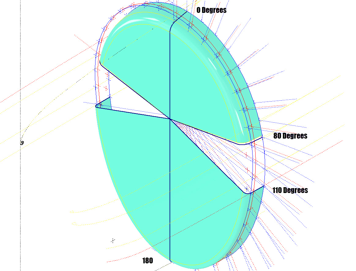

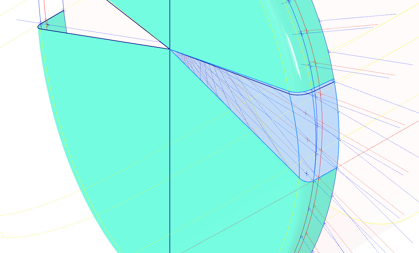
If we look at the CAD development of the Preheater surface model you can see I have developed the top profile with an ordinate radius of 2 7/16″ to the 80 degree increment and the lower section ordinate radius 1 7/16″ from 110 to 180-degree increment. However, when you loft the 2 profiles you can see the default curvature transition is not continuous…what we want is for the curved section to have smooth continuity throughout the transition.
I should note that the surface was developed to the 80-degree increment and then trimmed back to 79 degrees; I already had the construction sketches in the model…just saves some work.
Inventor like other CAD software will attempt to interpret the desired surface loft but it does not always achieve the desired result. This is easily corrected by selecting transition points within the Loft dialog which will enable a smoother transition.

Going back to my earlier comment on the projected curved section*; as per comments above; the CAD-interpreted surface may not produce the desired result with more complex geometry. So often the best way of doing this is to model that section separately ensuring finer control over the finished surface.
CAD Tip: The vertical face of this developed surface is flat, occasionally when lofting, sweeps or even applying a surface patch it is always a good idea to check the finished surface is actually flat and planar where expected. The way to check that a surface is planar is to select the New Sketch option using the surface as a sketch plane…if the surface is planar it will allow a sketch.
P-47 Engine Mount:
On the Republic Drawing #89P62101 for the Engine Mount the intersection point of the top diagonal brace with the centre of the front ring is not clear.


On the Front View, we have either a dimension of 8.75″ (1) or an Angle of 58.5 degrees (2). To verify which is the correct set out for the top brace we turn to the elevation view. Here we have a cross brace intersecting the top diagonal at 20 21/32″ (4) and 16.592″ (3). Drawing in this intersection point in conjunction with the known datum at the extreme right we project the centre line of the brace to intersect with the front ring.
This projected point is within 0.017837600 mm of the point determined by the dimension 8.75″ (1) and 1.057782238 mm where the angled line (2) intersects with the ring centre. This verifies that the actual point of intersection is the dimension 8.75″.
P-47 Fuselage Curvature Analysis:
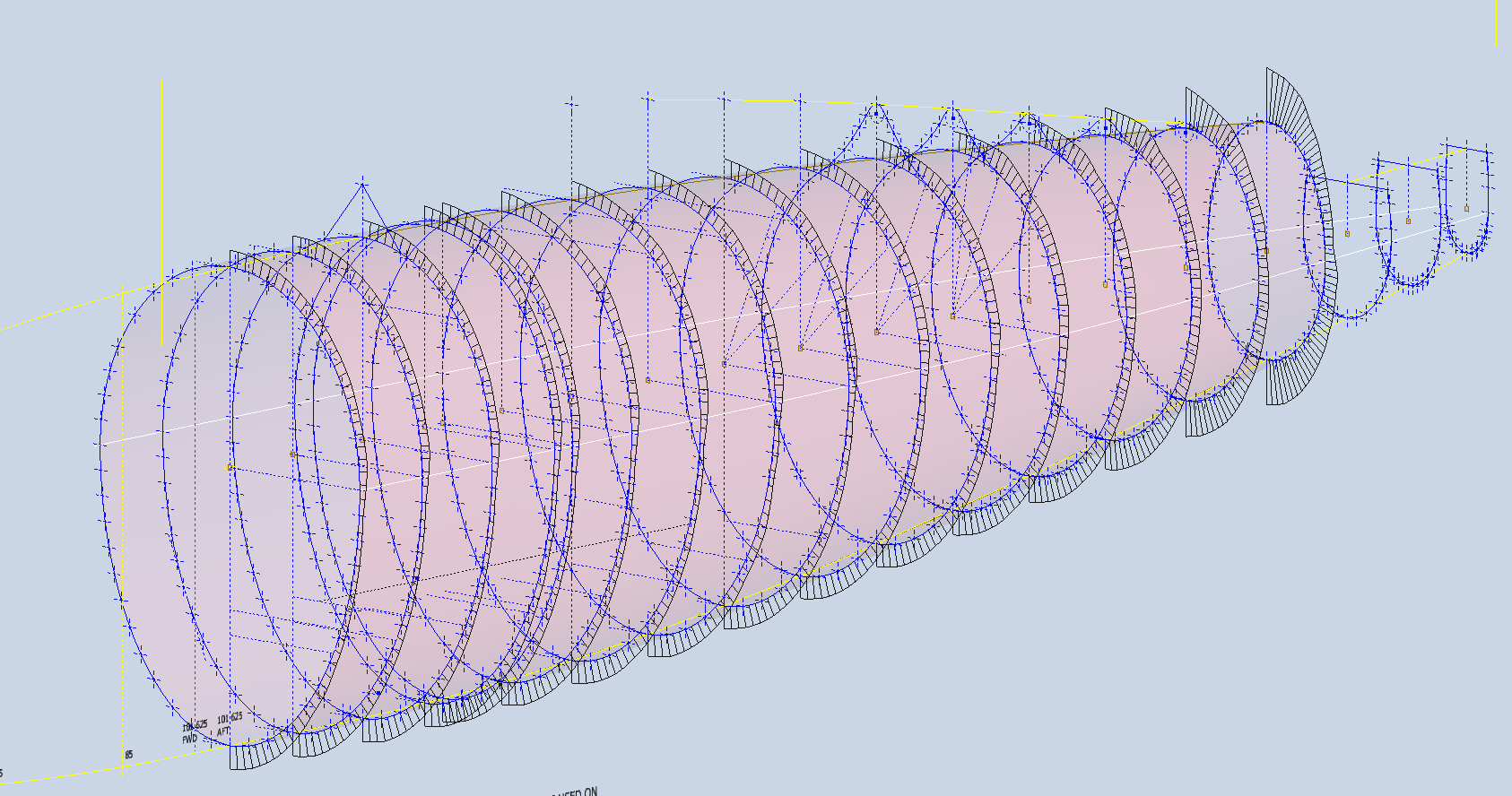
The following image shows the curvature analysis at each station of the fuselage. Only 4 rogue points were micro-adjusted to align correctly. What we are looking for here is not perfection but consistency. You will notice a small flattening of the side curves around the centre of the fuselage, which is fairly consistent throughout. The primary reason for doing this is to identify any points that will create a negative curvature or completely in the wrong position.
The next challenge is to identify the correct tangent points between the humped back ridge curves and the main fuselage. It may tempting to just profile a spline connecting all the points from the ridge curves and the main fuselage but this is likely to create small imperfections where the tight curves meet the main body profiles…so it is always best to do this separately.
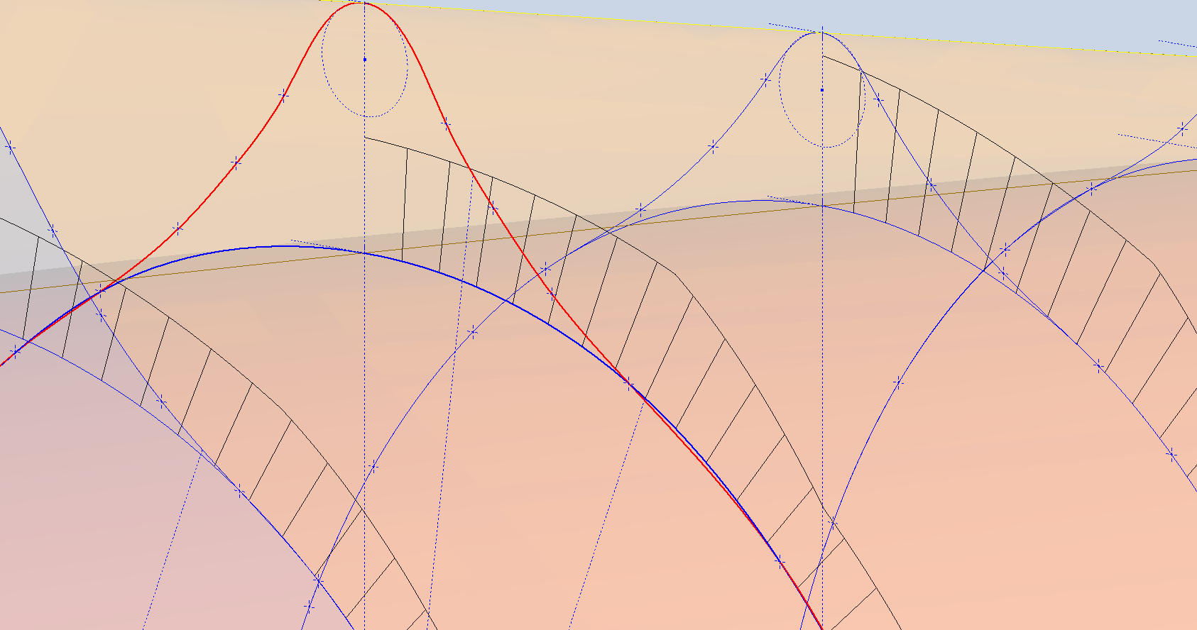
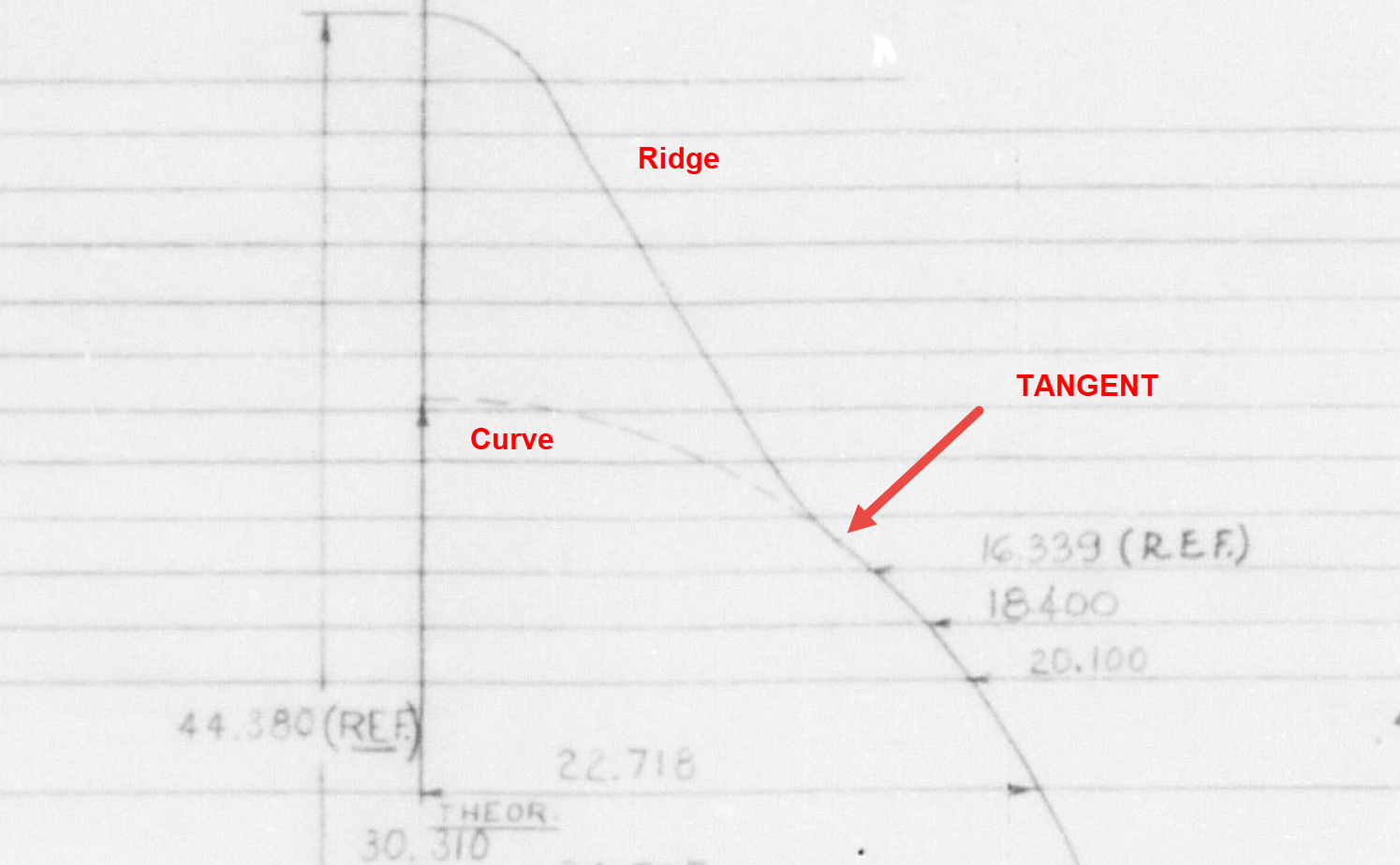
In the first image above the red line is the best fit spline connecting all profile points and you can see how it dips below the curved profile from the blue main fuselage curve profile. From the Republic ordinate drawing it is clear the intent is for the ridge profile to be tangent at the point of intersection.
The finished profiles will look something like this…

