Technote: Accurate Label Placement:
For instrumentation Panels, the location and size of text is very important to ensure clarity. This is usually well documented on the manufacturer’s blueprints so it is essential we get this right. In Inventor for example and I am sure it is equally similar in the many different CAD programs the key is the Text justification…let me show you.
First of all a quick update on the P-39 Restoration progress. Much of the recent discussions revolved around fabrication and 3D printing. As mentioned in the previous article this restoration is a static display for which many of the parts will be 3D printed, although the key aluminium panels will still be fabricated as such. The very latest part to be issued for fabrication is this small Switch Box on the Radio Console.
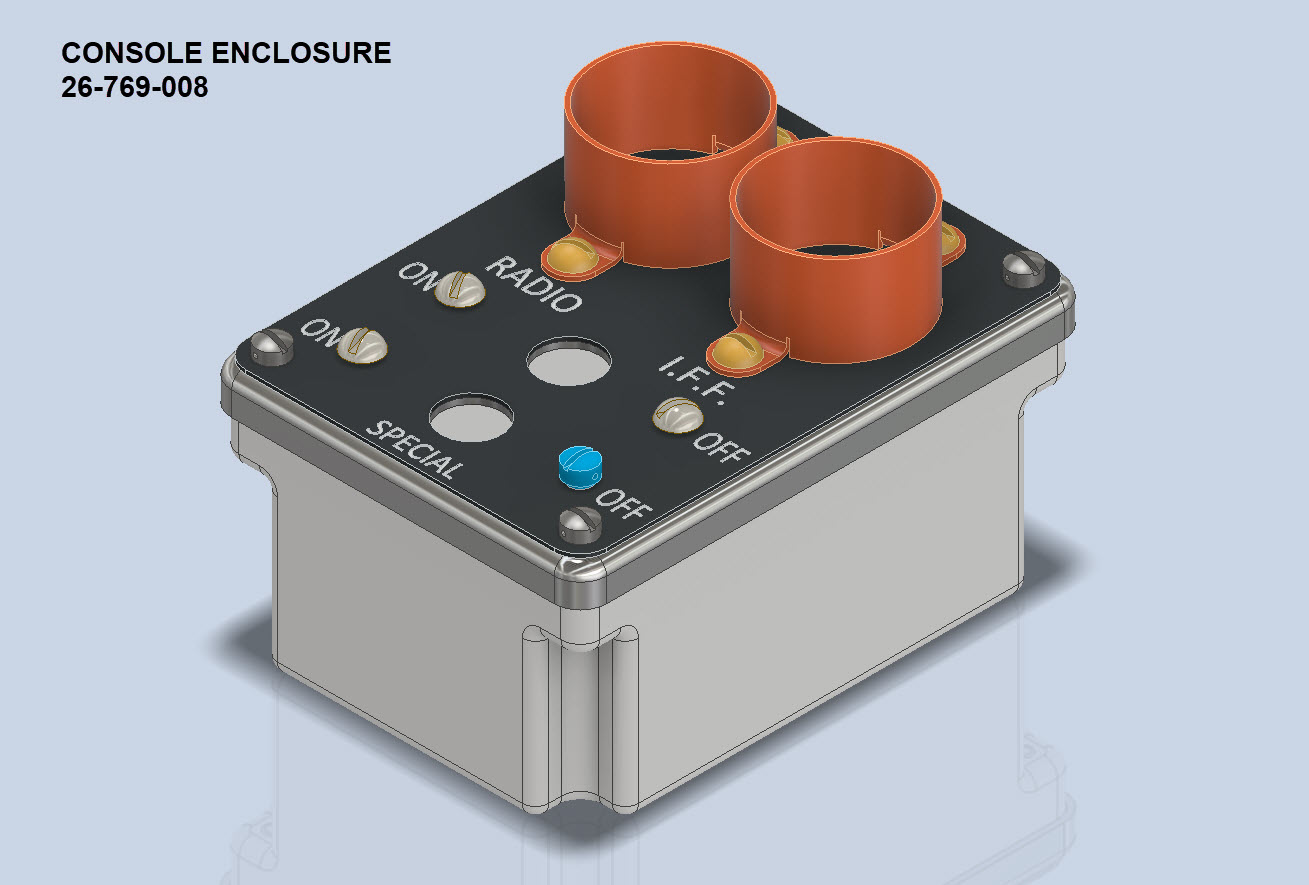

A surprisingly complex box which will be 3D printed and the Nameplate will probably be CNC. The dimensions of the main box are not defined on the Bell drawings so I had to interpolate from the known information and other Bell references to determine the final dimensions. This took into account the clearance from the Drive Shaft connecting flange which is in very close proximity to this box. This also fits quite well into our discussion here on Label Text Placement.
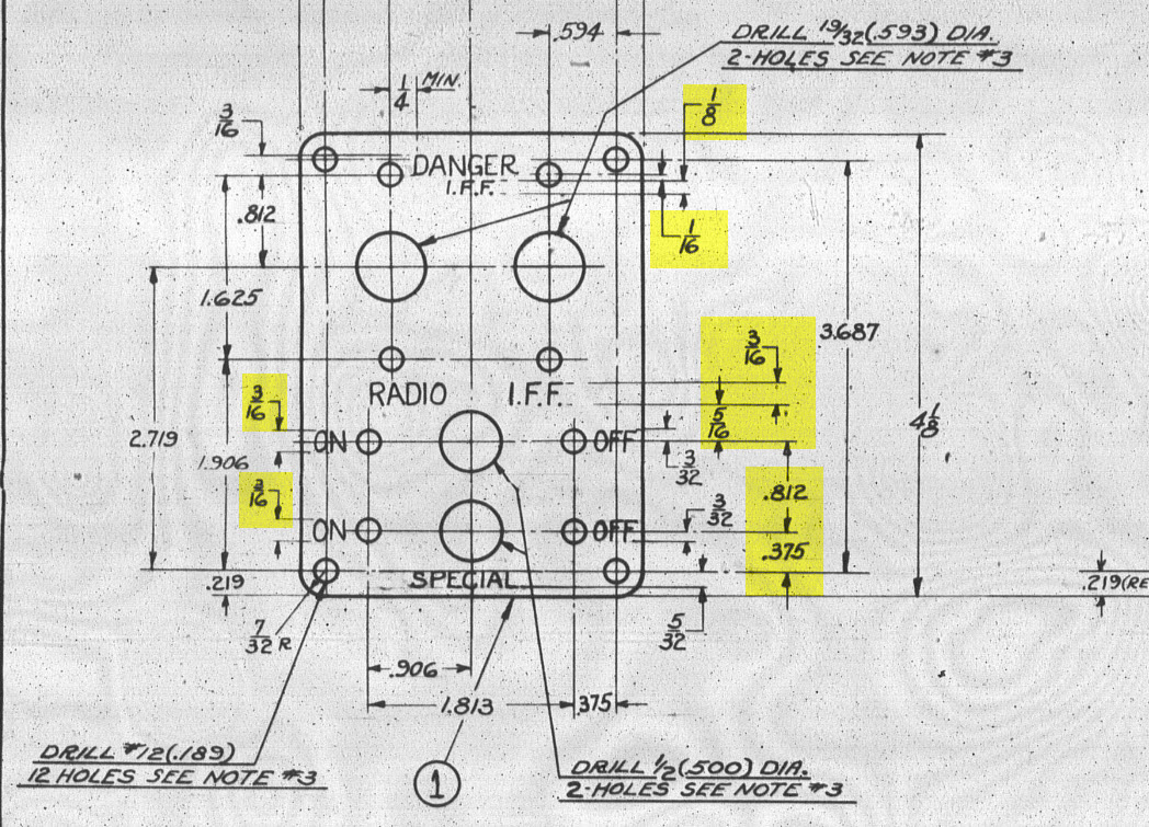
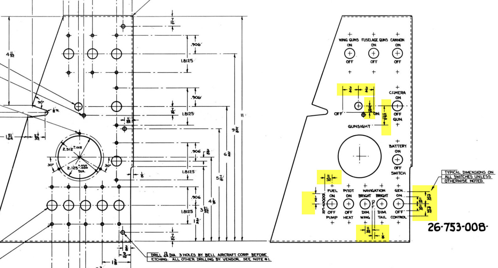
Typically on the Bell drawings, for example, the panel drawings include the height and location of the Label text similar to the following.
The way we do this in Inventor is by using the Text justification feature in the text editing box.
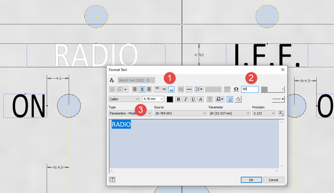

In the first image, we adjust the justification using the icons at “1”. If the dimension to the text label is to the bottom of the text we set the vertical justification to the bottom and if the placement horizontally is to the centre we centre the justification. When you exit the Text editing box a Text outline box is shown in dotted (this is optional so make sure you switch that on). The appropriate edge of the dotted line frame automatically aligns with the justification of the text entities. This dotted outline can be dimensioned and constrained as you would any graphic sketch entity. The second image shows some examples of how the dimensions of this outline relate to the justification.
It is not unusual for the overall width of the label text to also be specified in which case the “Stretch” value can be adjusted accordingly, entity “2”. At “3” we set the font and height, make sure you have the text highlighted in all cases or these adjustments will not be applied.
Interesting to note that the text outline can be useful if you require a frame around your text. The dotted lines can be changed to normal sketch lines and extruded or embossed as required.
There are a lot of features in the text editing dialogue which I may do as a technote further down the line but for now, to get the label text in exactly the right locations this is the way to do it.
