Technote: 3d Modeling to Clarify Assemblies
Interspersed throughout this blog are many examples of Technotes describing techniques and problem-solving primarily for 3d CAD modeling. Many of the part examples shown are actually created to address another major issue with Assemblies.
It is not uncommon for the assembly drawings to be either unclear or simply void of key information that would help establish relationships between sub-assemblies or parts. In many examples, it is simply that the reproduction of the microfilm prints is not sufficiently clear to comprehend what is going on, otherwise the omission of basic dimensional relationships.
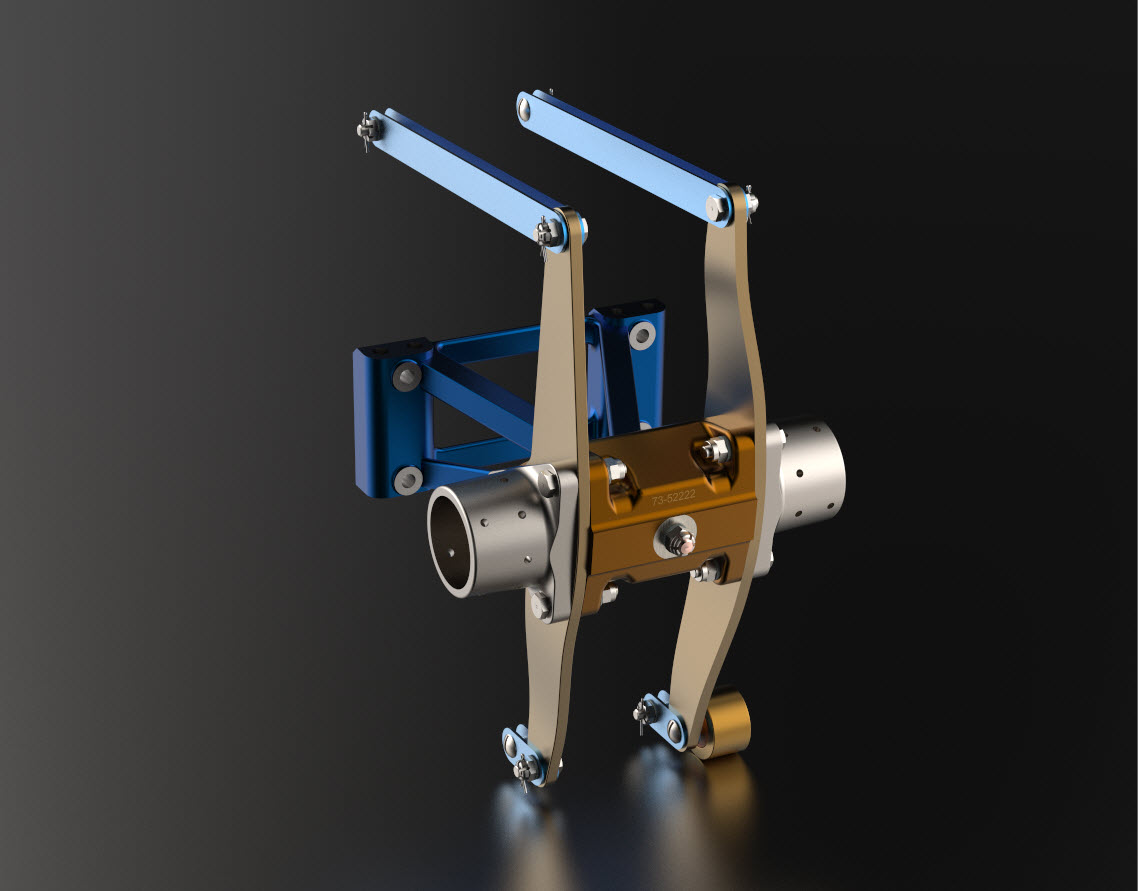
For the P-51 Mustang, I fully developed the rear Landing Gear mechanisms to clarify what the heck was going on as the NAA Assembly drawings details were obscured.


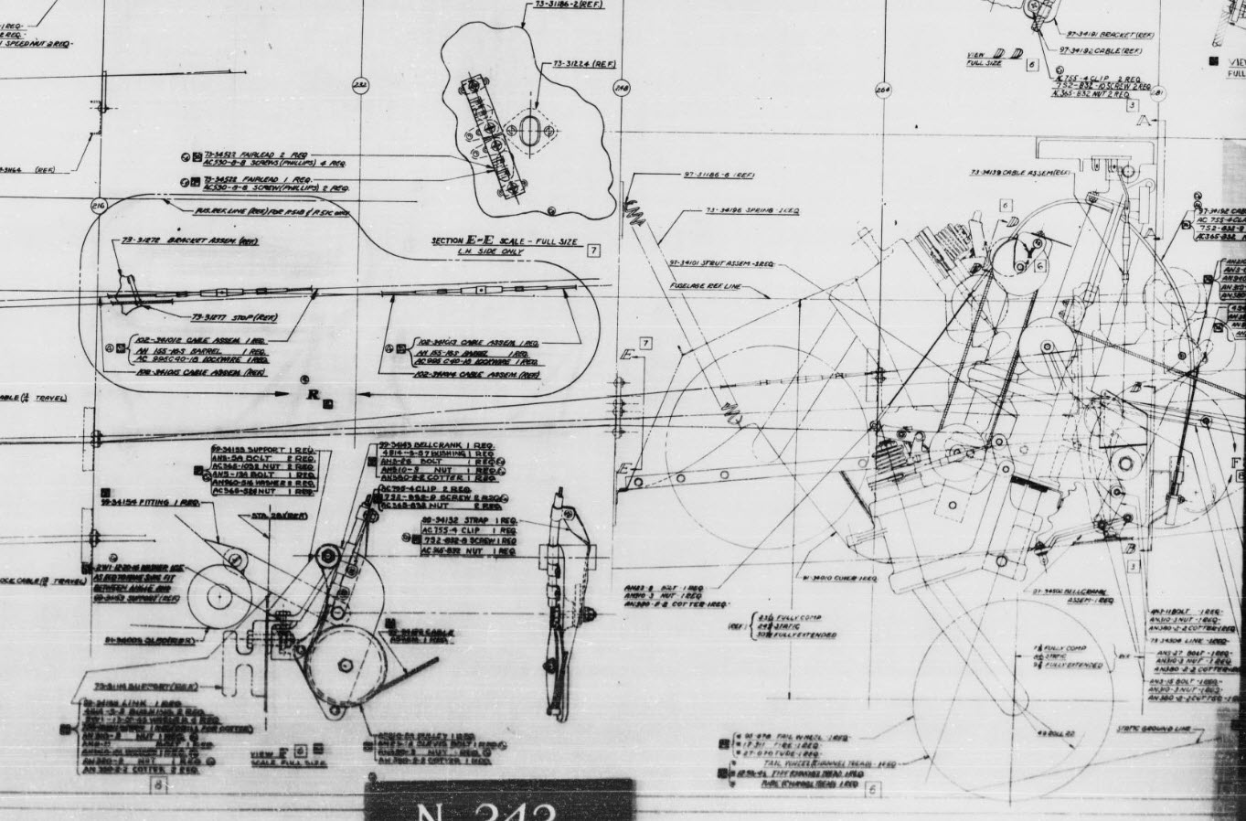
It is too often the case that general assembly drawings tend to be nothing more than an illustrated parts list with few key dimensions that define locations or relationships between the individual parts. This is also true for many of the sub-assemblies. For the P-51 Tailwheel sub-assemblies, I also developed 2D detail drawings showing key dimensions and parts lists. Ideally, I would have developed presentation drawings showing the exploded views of each of these assemblies to provide further clarification…perhaps a project for the future.


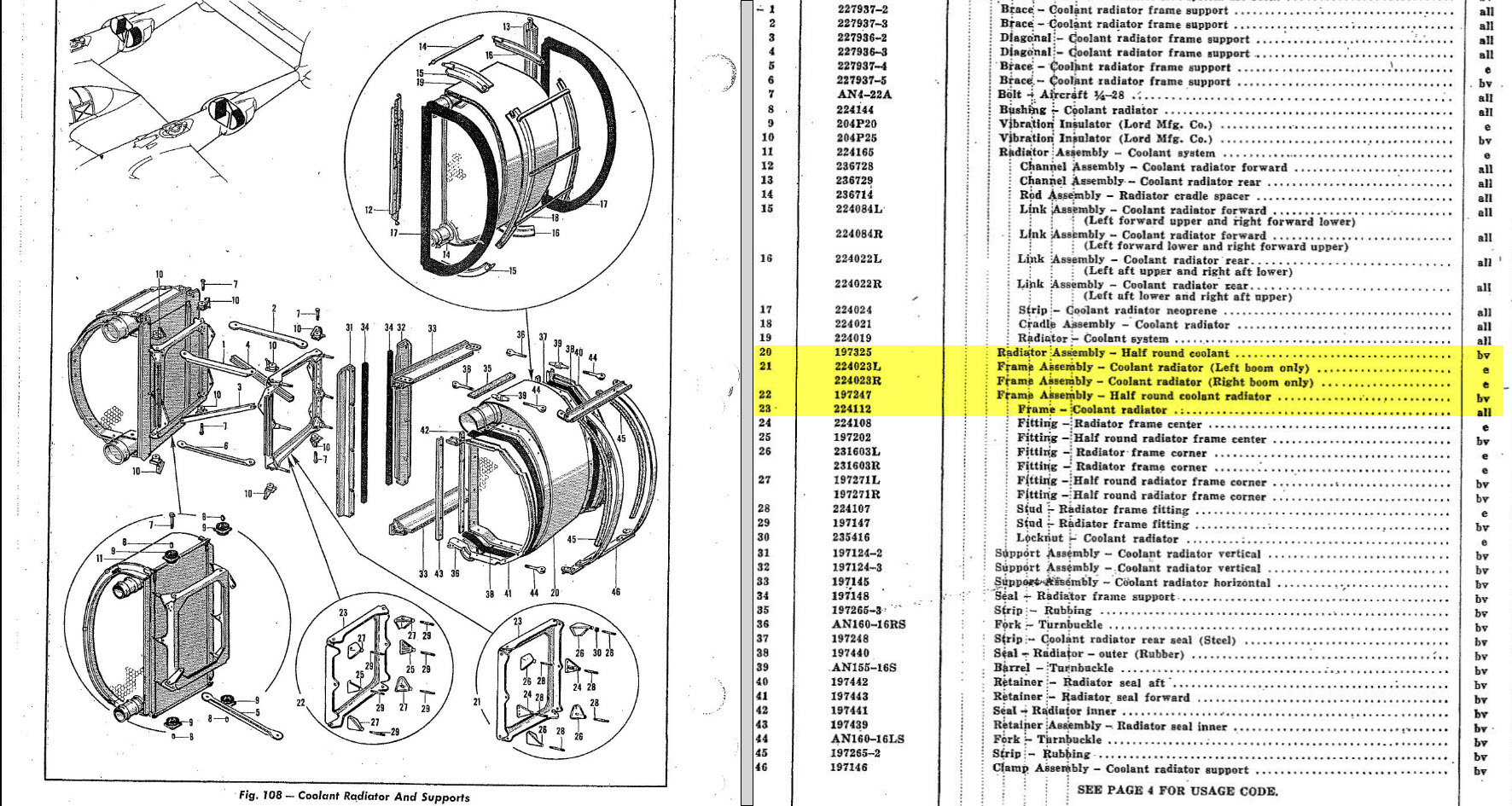
In the case of the P-38 Lightning, I have developed the Landing Gear assemblies to check the ordinate dimensions… which by the way are good. I now have the Coolant Radiator assembly which was again developed to check ordinate data but also for the same reasons as I did the models for the P-51 Tailwheel.


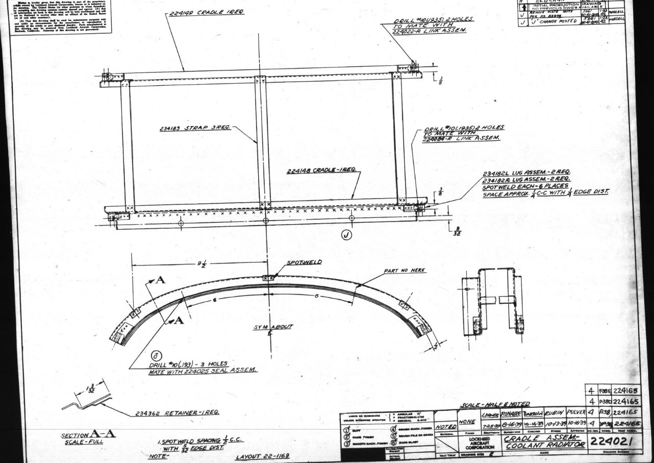
Typically the general assembly pictorially shows the sub-assemblies without any key dimensional information to define the location or part relationships and similarly, the sub-assembly for the clamp is not that much better. This is important stuff as occasionally they are the only reference material we have to help define ordinate data that is missing from the archive blueprints.
The Coolant Radiator is compromised by wrong dimensions as well…the top clamp cover, for example, had dimensions for the connection to the rod with the part drawing showing conflicting locations for different views of the same part.

The problem here is the connecting bracket item 224045 cannot possibly be 1″ from the edge of the cover plate whilst the overall dimension of 6 7/16″ prevails. I initially had located that bracket at 1 inch which seemed to be correct at the time because it fitted the part profile but when I introduced this into the assembly drawing it would not correctly align with the radiator. However, when I revised this using the 6 7/16 inch dimension it worked. That connecting part also caused more problems because the face of the part is machined 1/64″ which is not taken into account when positioning the part in the assembly.

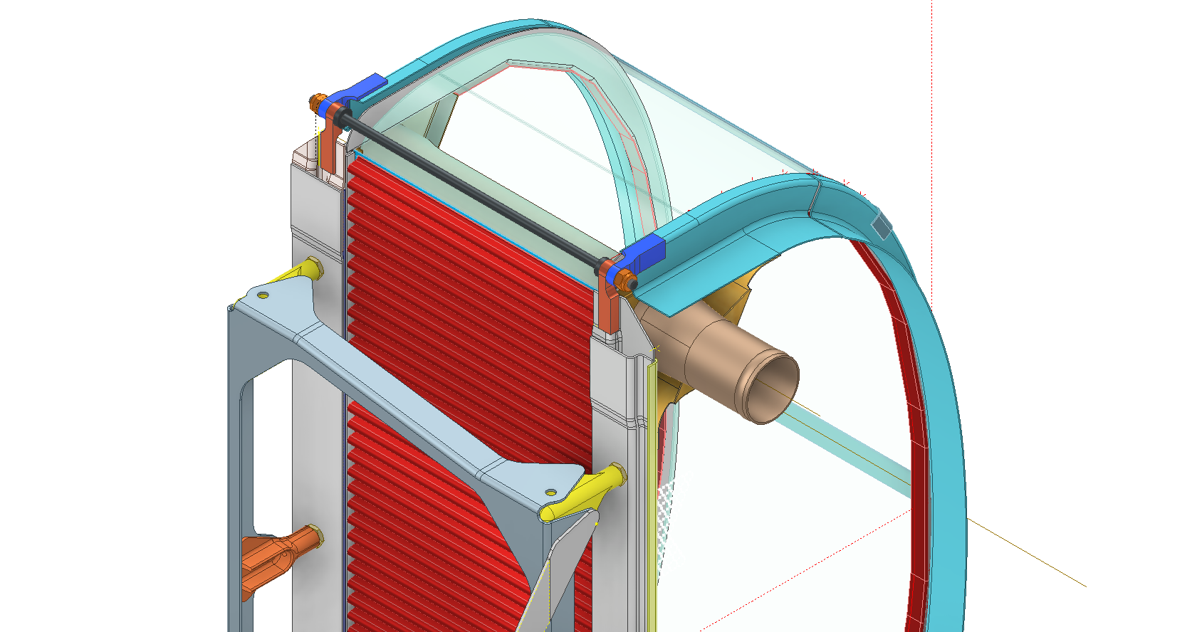

Accumulatively this resulted in the overall width of the clamp assembly being smaller than it should be. This only came to light when I modeled the 234183 almost inconspicuous part as the stated dimension of 9.25″ did not fit with my initial layout..my first thought was this may just be an oversight but when I tried to align the main support frame (in gray) it did not align correctly. I went through everything and realized that the machined face of the corner parts connecting to the rod as shown may not have been taken into account and when removed the alignment was better and the 9.25-inch dimension on the strap was now correct. I am convinced that there should be spacers/washers between those connecting parts but this is not apparent on the assembly drawings. There remains a small discrepancy of 0.8mm which I am unable to account for….as this mainly relates to a clamp mechanism that will be compressed on assembly it was probably not deemed important but when you are trying to establish baseline dimensions it is actually very important.
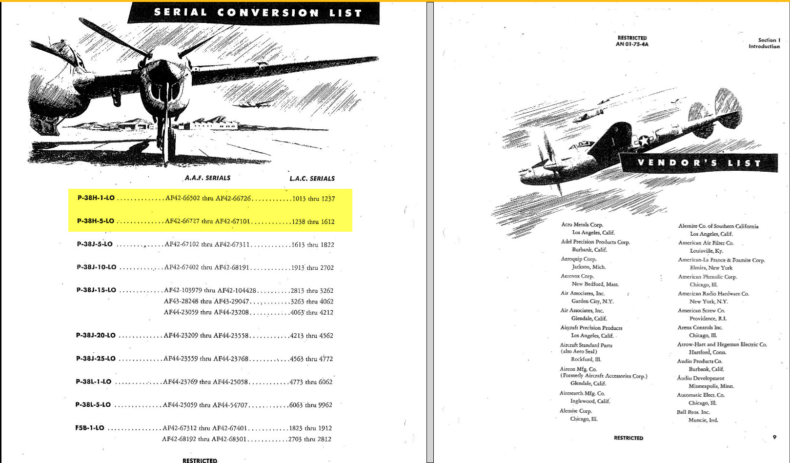
The Part catalogs generally are your first port of call when developing these assemblies but they do not contain the key dimensions you need so these 3d CAD models are essential to achieve clarity. Incidentally, while we are talking about part catalogs it is important to understand what parts belong to which version of the aircraft. For the P-38 Lightning, the first few pages list the version and serial numbers which in turn are listed elsewhere where a Usage code is assigned. In this case the “e” is essentially the P-38H and the “bv” is the P-38J. The P-38 Part catalogs tend to show the version variations on one page; which can be really daunting; whereas others may show the version differences on separate pages…so you have to be attentive.

As I mentioned at the beginning of this article the main purpose of these assembly models is to achieve clarity and to check dimensional relationships. I think this is very important stuff that would certainly benefit from exploded views in conjunction with clear assembly 2d drawings.

As usual, get in touch if you can help support my work. hughtechnotes@gmail.com
