Technote: AN115 Shackle Model:
Working my way through the various AN Standard components I thought it may be prudent to write up a quick Technote on modelling the AN115 Shackle.


At first glance, this seems to be a fairly straightforward item to model, however, getting the transition from the flat section to the curved ring is rather tricky. When you view this item on Google and look through the various images of the finished product there are visibly small variations in how this has been interpreted. Needless to say that I have my own interpretation to achieve a smooth integration while ensuring the integrity of the finished model.

First of all, ignore the bulge on the right-hand side…for some part numbers this area is elliptical and not round…so for development reasons I have purposely exaggerated the profile to test the iPart creation.
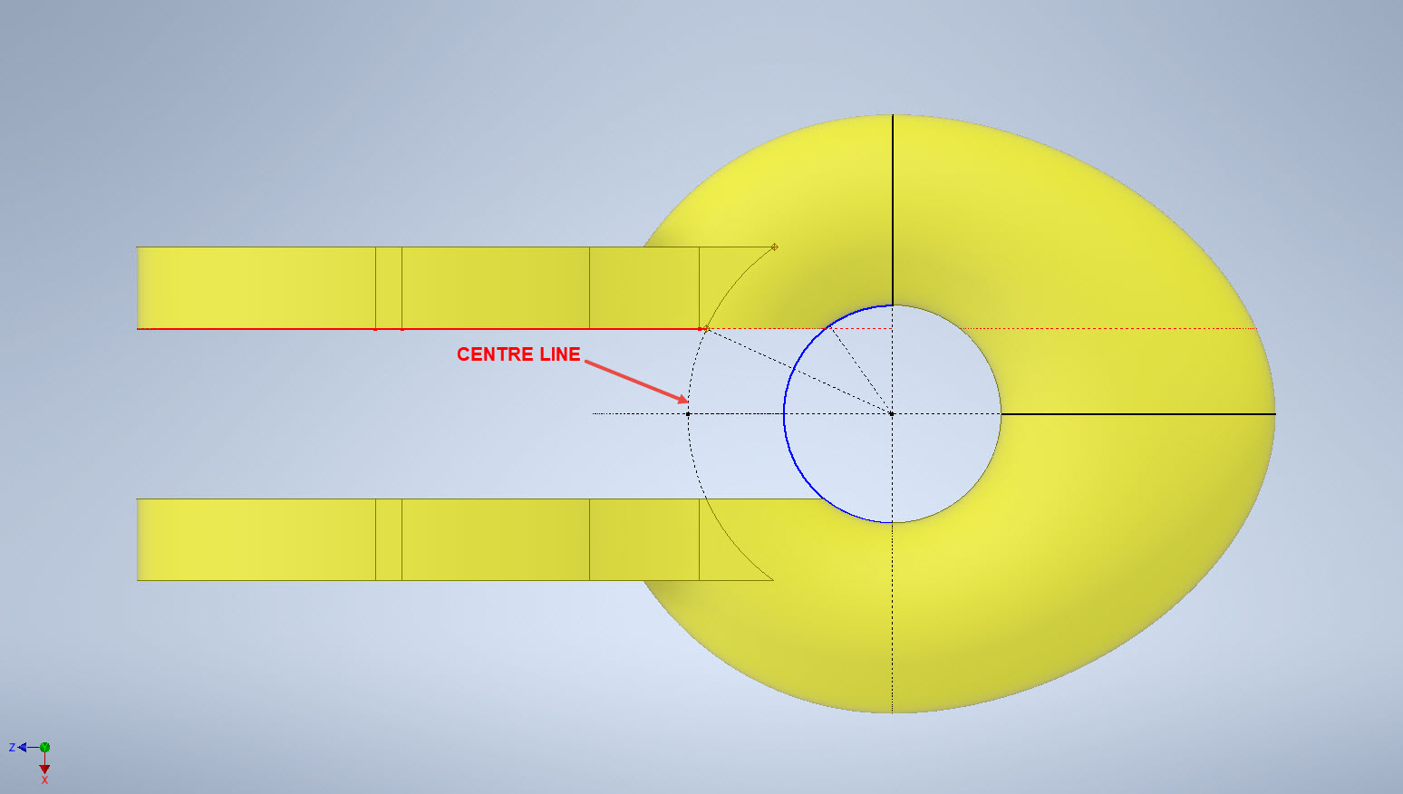
What I was looking for was to achieve a smooth transition along the edges of the flat portion to merge with the round profiles of the ring section. My first attempt was simply to have a curved edge at point “1” that was tangent to the ring and the edge of the flat section. However, that did not achieve a good result because the top and bottom surfaces of the flat section coincide with the ring at different points which created a small twist when lofting the sketch profiles.

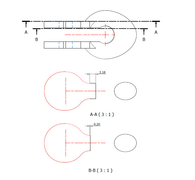
I found the best way of solving this was to introduce a small horizontal line tangent to the ring section profiles. For the inner sketch, this was only 0.2mm which translates to just over 2mm for the outer sketch. The points shown as “1” and “2” are the centre points projected from the ring centre line which is the start point for those sketched horizontal lines.
Now when we loft the 2 sketches we have a good square edge for the flat section…by the way, I should note that the flat section is initially lofted as a separate solid because we still have one step to do before we merge the solids into one. After lofting the flat sketches we still have to trim the resulting solid to follow the centre of the ring surface.

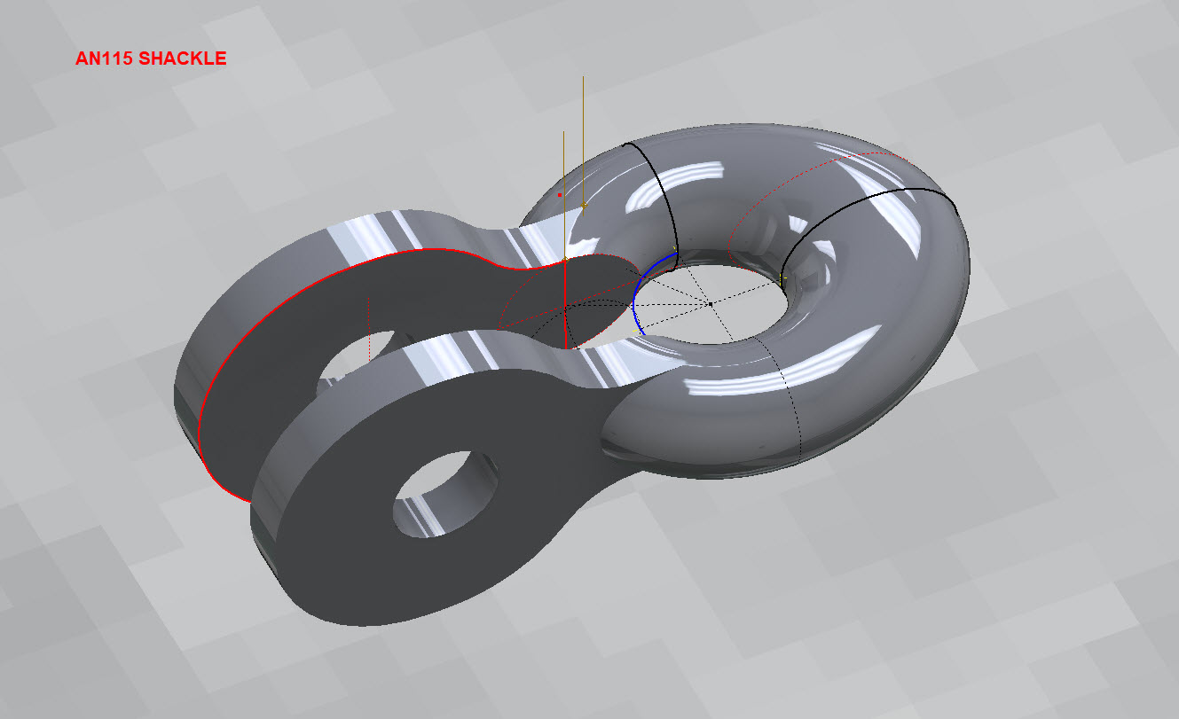
This is simply done by extruding a surface from the centre line of the ring as shown and then trim back the excess from the flat section model. Now we merge the 2 solids and we end up with a shackle that has a smooth transition from flat to ring without any twists or surface anomalies.
The bulge is still there on the final image…that will be gone once I finish filling out the table with the various part number dimensions.
So sometimes when you are modelling a complex item like this it often helps to introduce a minor feature (in this case a small 0.2mm line) to ensure that lofting and extrusion activities provide the desired end results.


AN481 Clevis Rod End:
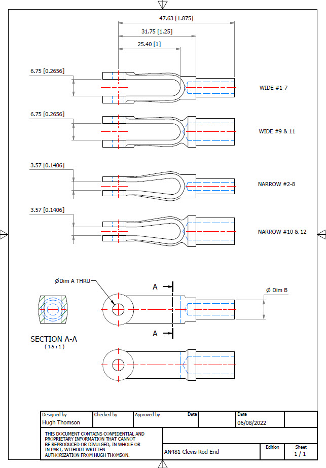
Another tricky item to model is the AN481 Clevis Rod End. There are 4 variations on the same model that comprise 2 sets each with a narrow gap and a wide gap. Technically it is possible to create all variations in one part file and use Suppress and Unsuppress options to exclude or include features…however, I decided not to do that because it can be a real pain adapting the model if the regeneration does not quite work the way one expects it to. The model is not that complicated so it was just as easy and to be honest much tidier to create separate part files for each variation.


As usual for further information please get in touch at Hughtechnotes@gmail.com
AN116 Shackle:
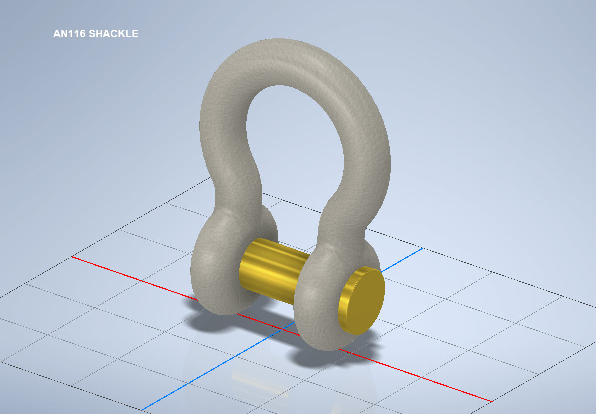


The AN116 Shackle PIn is shown with a rounded head which I decided not to model due to the lack of detailed information for this pin. I tend to shy away from modelling components where there are no specific dimensions. I am not sure this is critical except where accessibility for tightening the pin is a consideration.
The new Parts Library should be finished at the end of August…I will advise.

