Technote: Bell P-39 Airacobra Updated Model
For the last 3 weeks I have been working on an update to the Bell P-39 Airacobra Ordinate and CAD dataset. The original P-39 was intended to be a personal study of the construction and structure and therefore never actually finished. However following a request from a good friend who asked if I could do some work on the Vertical and Horizontal Stabilisers I decided to have a look and see what I could do.

This model is brand new, effectively replacing the old model with a new direction in how these models are presented. The majority of the CAD/Ordinate datasets comprise extensive spreadsheets of dimensional data, drawings and a 3d cad model of the profiles. The idea is that all this data will provide the end-user with a number of options for their own projects. To develop their own models, from either the 3D cad model provided, the 2d drawings or using the spreadsheet data. Fundamental to all this is getting the core dimensions correct which was my primary goal.

I have extended that concept further by applying a base material thickness to the frames and ribs using the Sheet Metal function. For reasons of clarity it is just the basic web profile but what it does is provide the end-user with an actual solid 3d model; dimensionally correct. This can be further utilised for production or used for RC models with the basic frames in place.
This development came about as a consequence of building the Horizontal Stabiliser. This was hampered due to a number of significant Bell drawings that don’t seem to exist as well as a few-dimensional error in the drawings I do have.

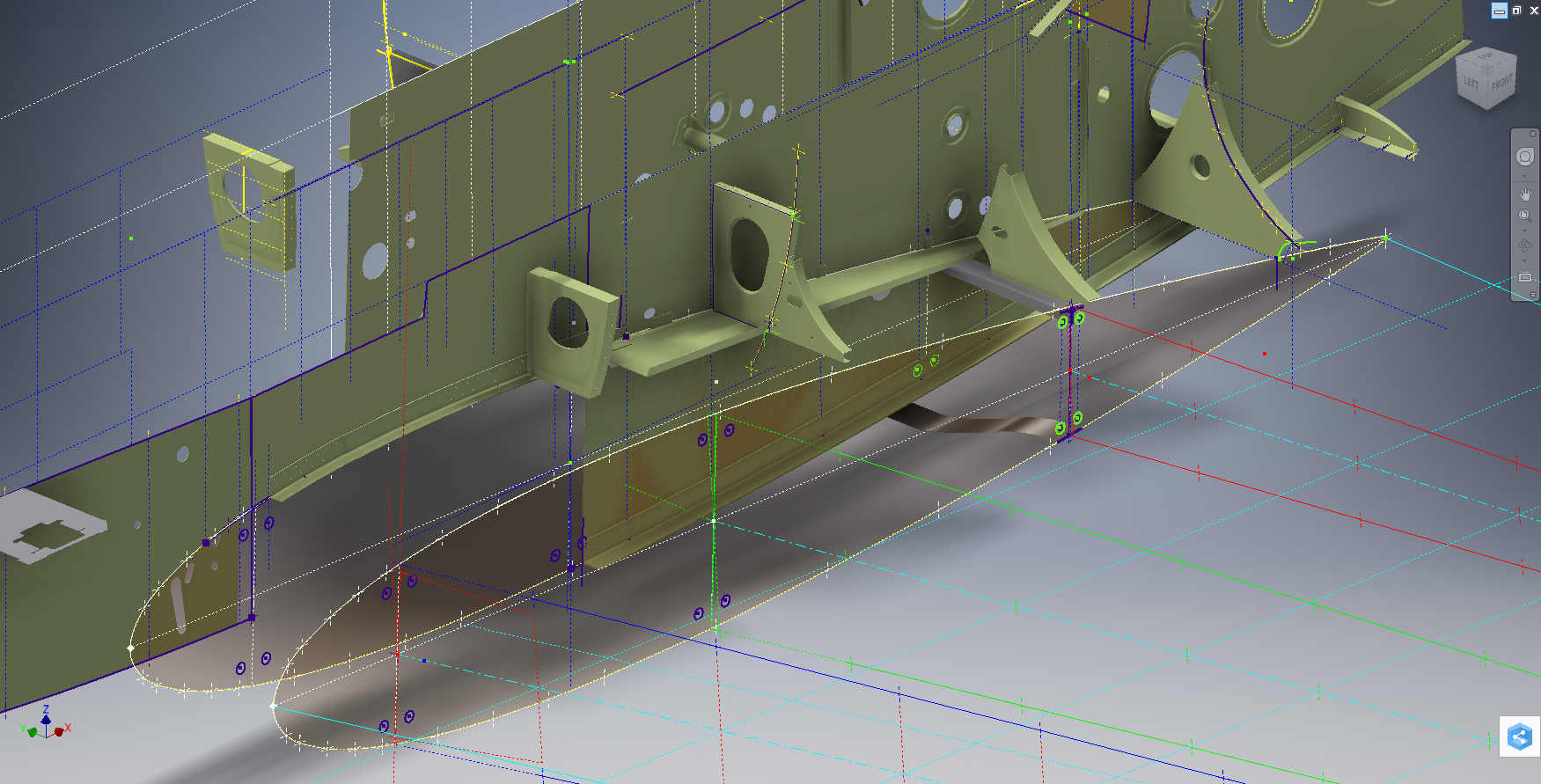
Developing this model required a lot of research to achieve the most accurate model possible for the P-39 Stabiliser. For example, the angle noted at “3” is defined on the Bell drawings as 13 degrees but when you check the layout against the Jig mounting points on the fuselage the angle is actually 13.1127 degrees. The material thickness of the ribs was an important factor when calculating this angle.
The dimension at “1” is not on the drawings but I did eventually find this quoted on a NACA Wartime report which aligns perfectly with expectations. The Leading Edge sweep angle is derived after I developed the LE ribs and aligned with known information. This is close and guaranteed to be within plus or minus 0.2 degrees. I have also written to a few companies that have P-39s to see if they are able to verify this angle. Update: Note the leading edge angle has been verified with a new value; see later post on this blog dated 12 July 2022.
The new P-39 Airacobra model and Excel spreadsheets are now online. Dimensionally it covers all aspects, wings, fuselage and empennage. There is also a copy of the old model which is still relevant.
Old Model (more 3d cad bits):
The plan is eventually to revisit the previous CAD Models for the other aircraft projects and add the web material thickness as I have done with the new study. This adds value to the potential use of these models far beyond what I initially intended.
As usual for more information drop me a line at hughtechnotes@gmail.com

Do you have drawings / blueprints for carb air inlet scoop behind cockpit . Original was made from aluminum . Do you have layout drawing.We care restoring a P39 in Chino , California. George Orff george.orff@gmail.com
Yes, I do. The Bell drawing is 14-615-002 which includes the dimensions of the intake profiles. For further information please drop me a line at hughtechnotes@gmail.com
This brings up some questions for me. The P-39 drawings I have show the spar angle for the horizontal to be 13 1/2 degrees. I’ll have to look into this more.
If you are referring to the angle of the stabiliser support bracket [12-219-001] that is defined as 13 degrees + or – 0.25 degrees. It is important in all cases where Jig dimensions are given to work to those as often bracket angular dimensions are rounded up. The P-39 drawings you have are the same ones I have, in fact all blueprints for the P-39 originated here including the ones on Aircorps. I hope this helps.
No, I was actually referring to the spar (12-211-501), but I understand. This brings up another question then. You mention working to the jig dimension when given. One of the horizontal attach bracket jig dimensions is given as 17.25″. Can I ask why you chose to use 17.236″? It’s not much of a difference, but that could throw other things off.
Also our project came with blueprints, many of them don’t show up in Aircorps Library. I’m assuming they just haven’t uploaded them yet?
Clarifying my previous comment I should note that where there are no conflicts the JIG dimensions should prevail however in this particular case; if I recall correctly; that dimension resulted from the 9.58mm offsets taking into account the sheet thickness. It is not possible to have the offsets at 9.58mm and arrive at exactly 17.25″. It is though within manufacturing tolerances. I have a whole library on manufacturing if you are interested in that.