P-38 Lightning: New Project
New Ordinate/CAD Project: The Lockheed P-38 Lightning is an American single-seated, twin piston-engined fighter aircraft that was used during World War II. Developed for the United States Army Air Corps by the Lockheed Corporation, the P-38 incorporated a distinctive twin-boom design with a central nacelle containing the cockpit and armament.

This project will dissect the complexity of the aircraft dimensions with fully developed spreadsheets, CAD models and drawings. I have drifted back and forth on this project over the last few months, studying the blueprints in detail to determine the best way of presenting the data in a usable format.
Surprisingly the wings are probably one the most complex parts of this study. The complexity comes about as a consequence of how the dimensional data has been recorded. For example, the wing chord is at a dihedral angle of over 5 degrees with the wing ribs actually perpendicular to the ground plane.
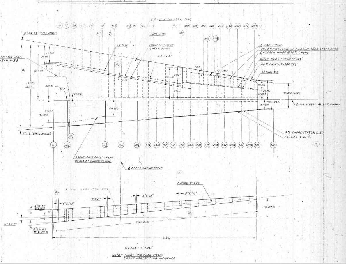
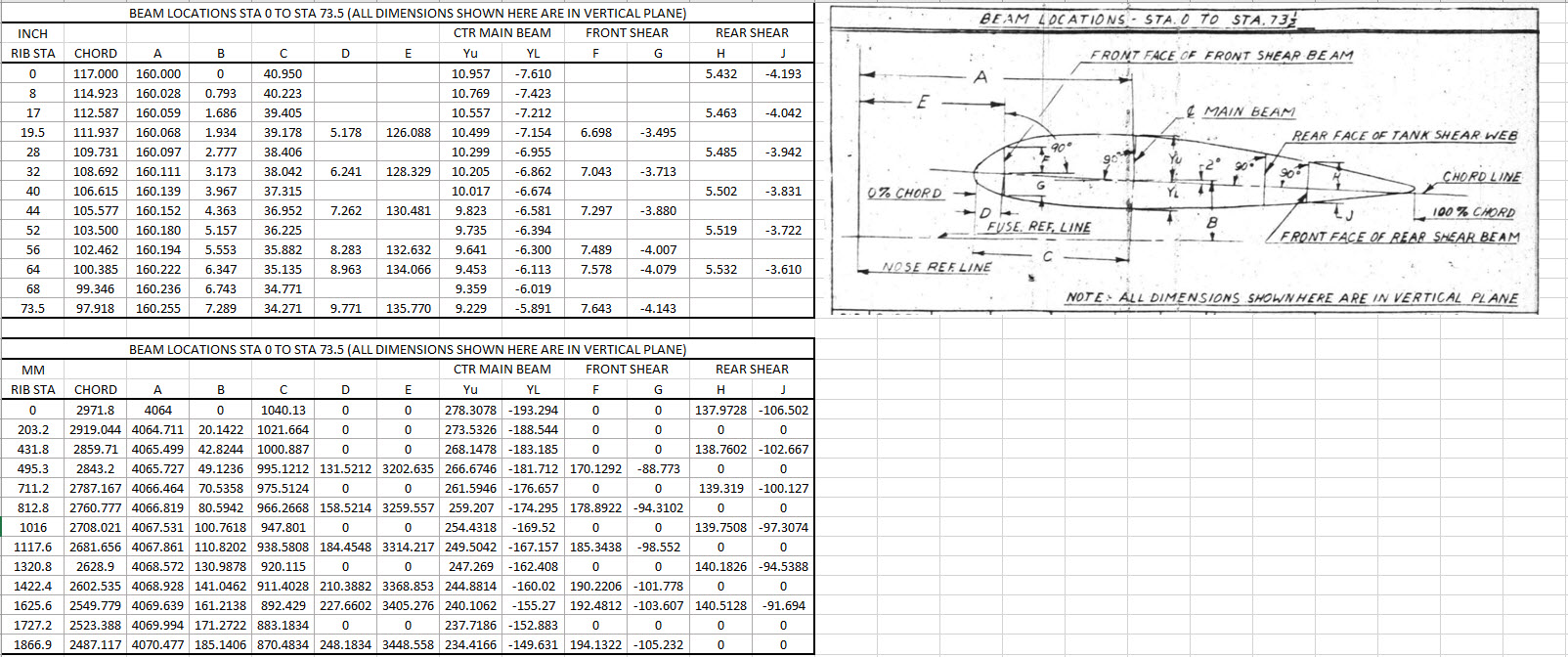
When we define the wing ribs we are actually working on a vertical plane angled to the wing chord line with the main beam and rear shear beams perpendicular to the chord on section. We also have the dimensions for the basic wing airfoil profile. Initially, I will record the rib dimensional information and generate the correct array of points at each Station. Then I shall calculate the airfoil profile at each station based on the given formulae Yu = YuT+(YuL-YuT)A. This should give us a means of verifying the tabulated data, for example; the table values for the Main Beam on 35% chord should match with the calculated airfoil values.

The plan is to record the dimensions as noted, vertical, horizontal and chord aligned in inches and millimetres exactly as defined on the original blueprints. Then I will extrapolate the X, Y, Z, coordinates for each point taking into account the chord angle of 2 degrees so that we can simply transpose these points directly into CAD at the correct positions relative to the origin point where the Nose Ref Line intersects with the Fuselage Ref Line.
The other caveat to all this is the 0% chord line is actually set back from the leading edge. There is yet another table of dimensions that relates the curvature of the leading edge to the 0% chord line. Ultimately to define the wing ordinates will involve a lot of work and then checking to ensure accuracy and correct alignment with the airfoil claculated profiles. At the end of the day, it is about making sense of all this fragmented information into a workable solution that makes it easier to interpret and use in any CAD system.
This is essentially how I work with all these Ordinate/CAD datasets. It is not just about recording information but also to check that the information works and that the end-user can transpose this into whatever system they are using. It is quite common for the information on the blueprints to be obscured, missing or simply illegible which usually requires a fair amount of time searching for answers. To complete this project I estimate something in the region of 300 manhours.
Update: 26th April 2022:
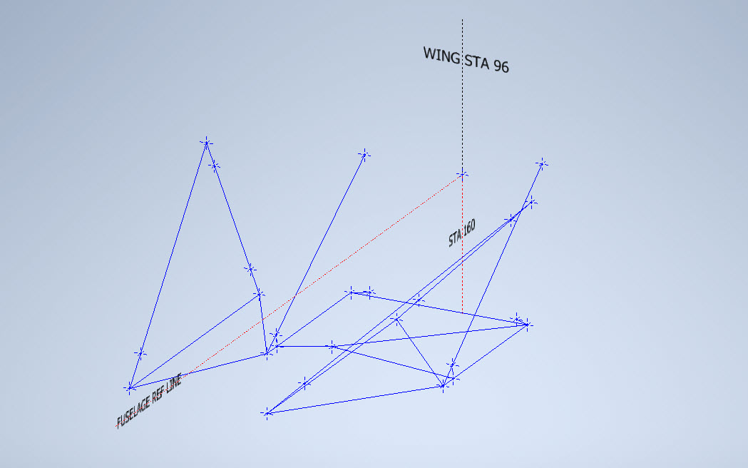
I have not yet decided on how best to present the Wing Ordinate dataset. I am looking at establishing check tables that will effectively compare the noted tabulated dimensions on the Blueprints with the calculated values. Also, we need to derive locational information directly from the wing plan CAD drawing for the Rear Shear beam and do a calculated check. Just to give you some idea of where I am going with this see screenshot below. As I mentioned above, the information on the drawings is fragmented so it is important that the excel spreadsheet data is presented in a clear and legible manner. Just now it is a bit of a muddle.
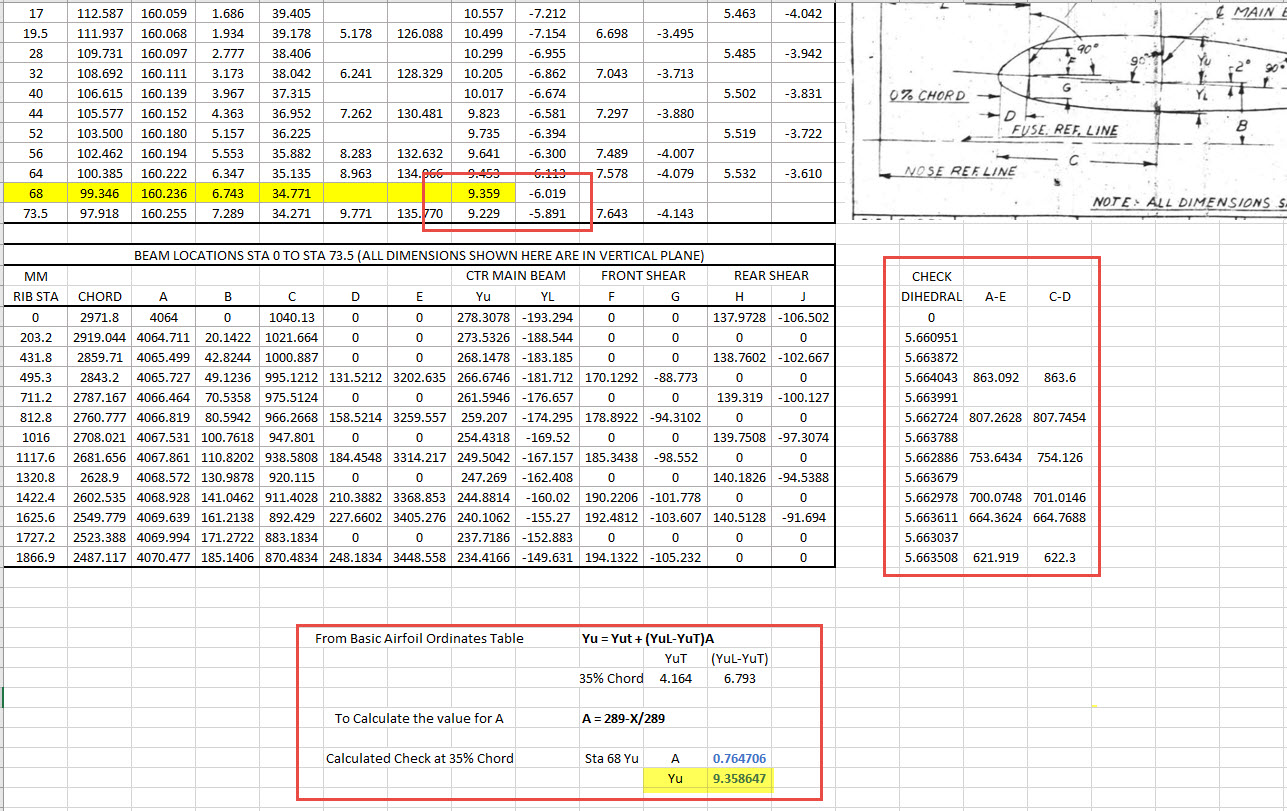
A quick update: Have rearranged the spreadsheet now with calculated values in lieu of listed values so the CAD model will be considerably more accurate. Calculated values are in blue text.

The rest of the Rib station tables will be added with similar calculated values and then I shall create a second worksheet with the airfoils for each corresponding station. The final sequence will be the extrapolation of 3D Ordinate points from a single datum so it will be possible to build an entire wing just from one collection of X, Y, and Z coordinates in one step. At least up to STA 254…still need to figure out the intricacies of the wingtip geometry.


Ordinates for each wing STA profile are calculated and recorded as shown. The highlighted rows at the 35% chord, are checked with those corresponding values listed in the tables above from the Lockheed original drawings. By the way, the drawing on the right is the Basic Layout Engine Mounts…there are 2 variations on this; both of which will be developed.
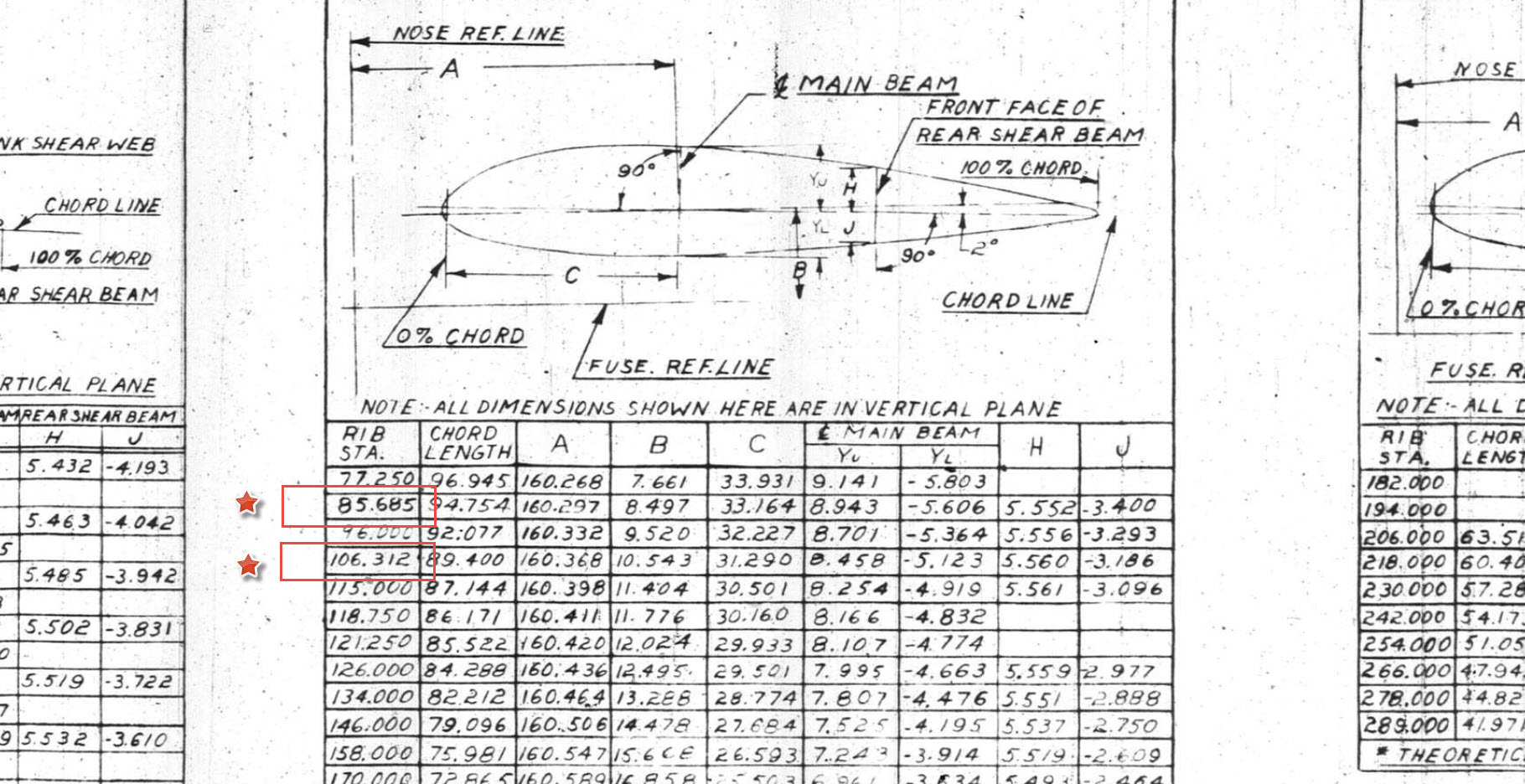
In the above screenshot, I have highlighted 2 minor corrections to the wing rib locations. They should be the decimal value for 85 11/16″ and 106 5/16″.

Update 3rd May 2022:
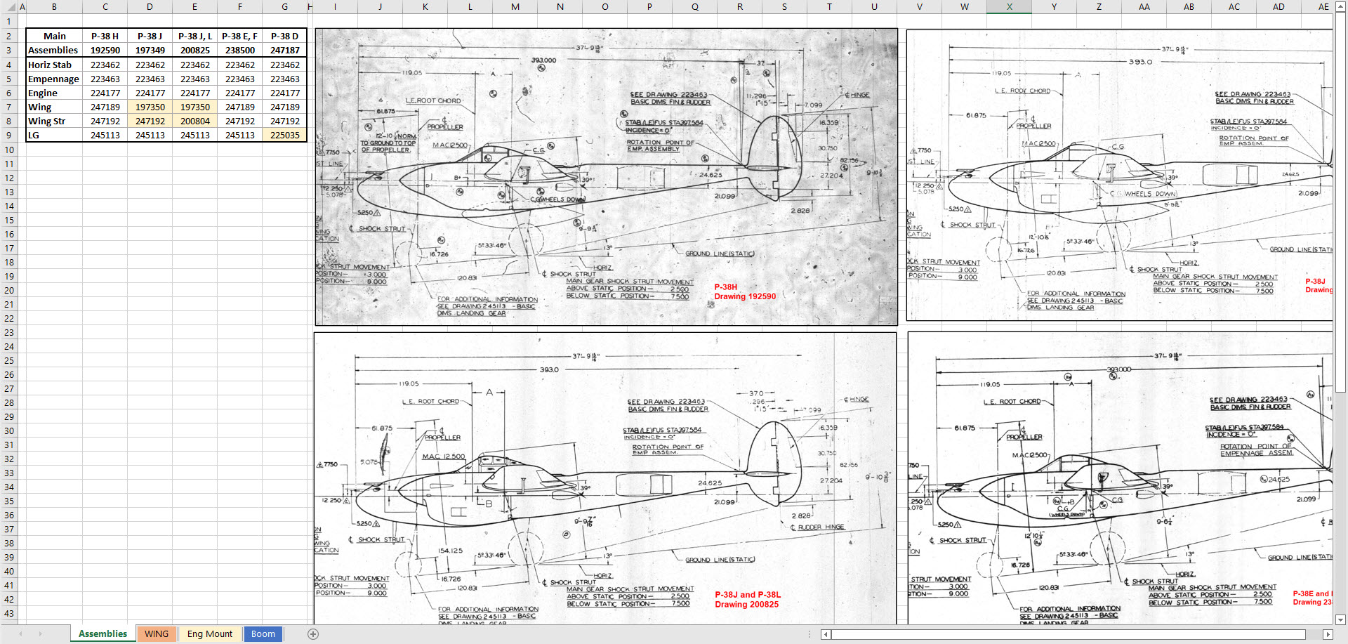
Have made good progress on the datasets for the Wing, Boom and Engine Mounts. Whilst working on this project I thought it may be prudent to compile an assembly list for each aircraft type for the basic dimension layouts as shown below. I plan to do a Technote shortly updating work methods using the ordinate dataset from Excel spreadsheets and include information on Sketch coordinate systems; manipulating the X, Y, Z-axis locally…so look out for that.