de Havilland Tiger Moth DH82: Fuselage Gussets
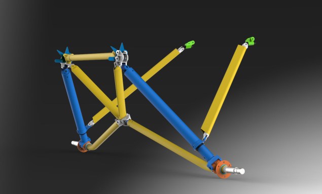
Looking back through a previous project for the Tiger Moth I had some notes relating to the fuselage gussets. The rear fuselage is a bit of a puzzle when it comes to the strengthening gussets at the truss joints.
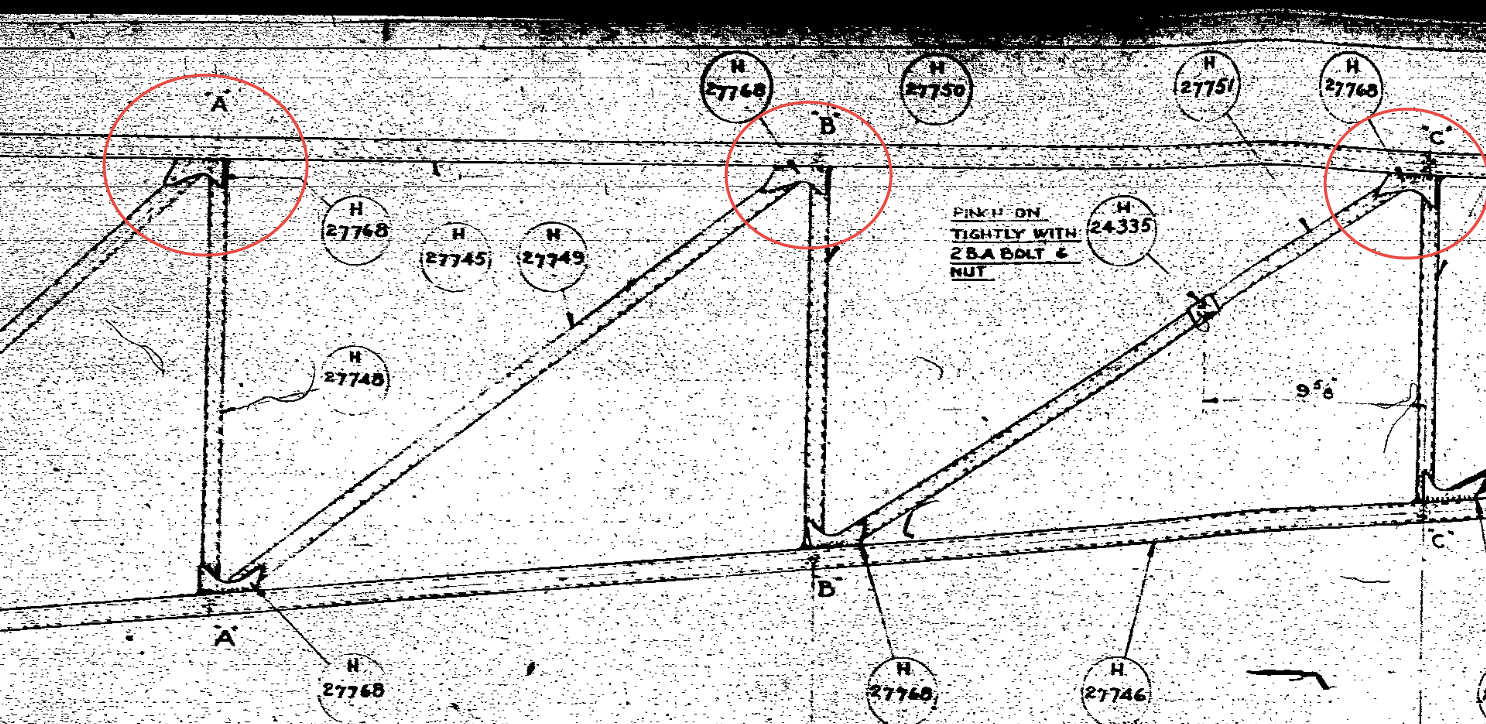 This is a scrap view of the de Havilland rear fuselage drawing on which I have indicated 3 gusset locations. The first thing that comes to mind is that for each joint the diagonal truss member is at a different angle but the gusset plate in each case is the same part number.
 On this same drawing, we have an enlarged detail view showing the minimum weld requirements for each of these gusset joints which cannot be achieved if the gusset plates above are all the same size!
In fact, for 2 of the three joints, the gusset plate extends beyond the diagonal truss member making it impossible to achieve the weld criteria. This is actually quite clear in the first image and modeled in the following.
 I started my engineering career on the drawing board so I understand why in many cases they have done this to maintain consistency of parts and minimise variations, but if its not fully engaging then its bound to be less effective.
As you can see in the model the gusset plate is not even close to the center of the strut and certainly would not achieve the 0.25″ weld.
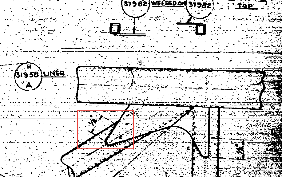
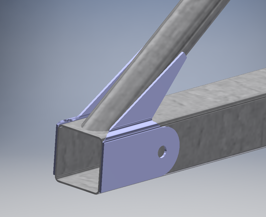 Another odd example is the bottom truss end gusset where it splices with the front fuselage truss.
This is actually detailed as a flat plate on the dH drawings, but for it to fit correctly it needs to be jogged; as shown; to coincide with the diagonal struts, otherwise, you would have to fill the gap with weld.
The material thickness for the tubes and the plate are less than 1mm, so depositing large amounts of weld in these areas is not advised.
The gusset plate also fits flush with the end of the tube and is noted on the drawing as requiring an edge weld. I think if I was designing this I would have the plate set back from the end of the tube allowing a full profile weld all around.
What makes this odd is that for other aspects of this aircraft design they have gone into great detail with gussets elsewhere, clearly dimensioning jogs with separate plates for individual joints.
I should note that there is an insert piece required to close the main tube which is not modeled yet.
When I study these aircraft designs, whether it be the Ta152, the Mustang, Spitfire or the Tiger Moth I try to understand the reasons why things are done the way they are. In many cases it could be driven by manufacturing criteria, availability of materials, expediency, a need to minimize variation or in some cases just down to the individual draftsman.
There is some debate about the effectiveness of these gussets and whether or not they are actually required. I have no opinion on these debates, the fact remains that they are part of the design and with some minor dimensional adjustment can be fitted correctly in compliance with the specified criteria.
I quite like the Tiger Moth, it is a practical design with many examples still flying worldwide. I hope that someday I can collate the necessary information to finish this project.