Spline Technote:
Splines are an absolute necessity when developing the finished profiles from the ordinate points; which occasionally throws up some unexpected results. Invariably at some point we need to manage the curvature of the splines in order to achieve the desired result.
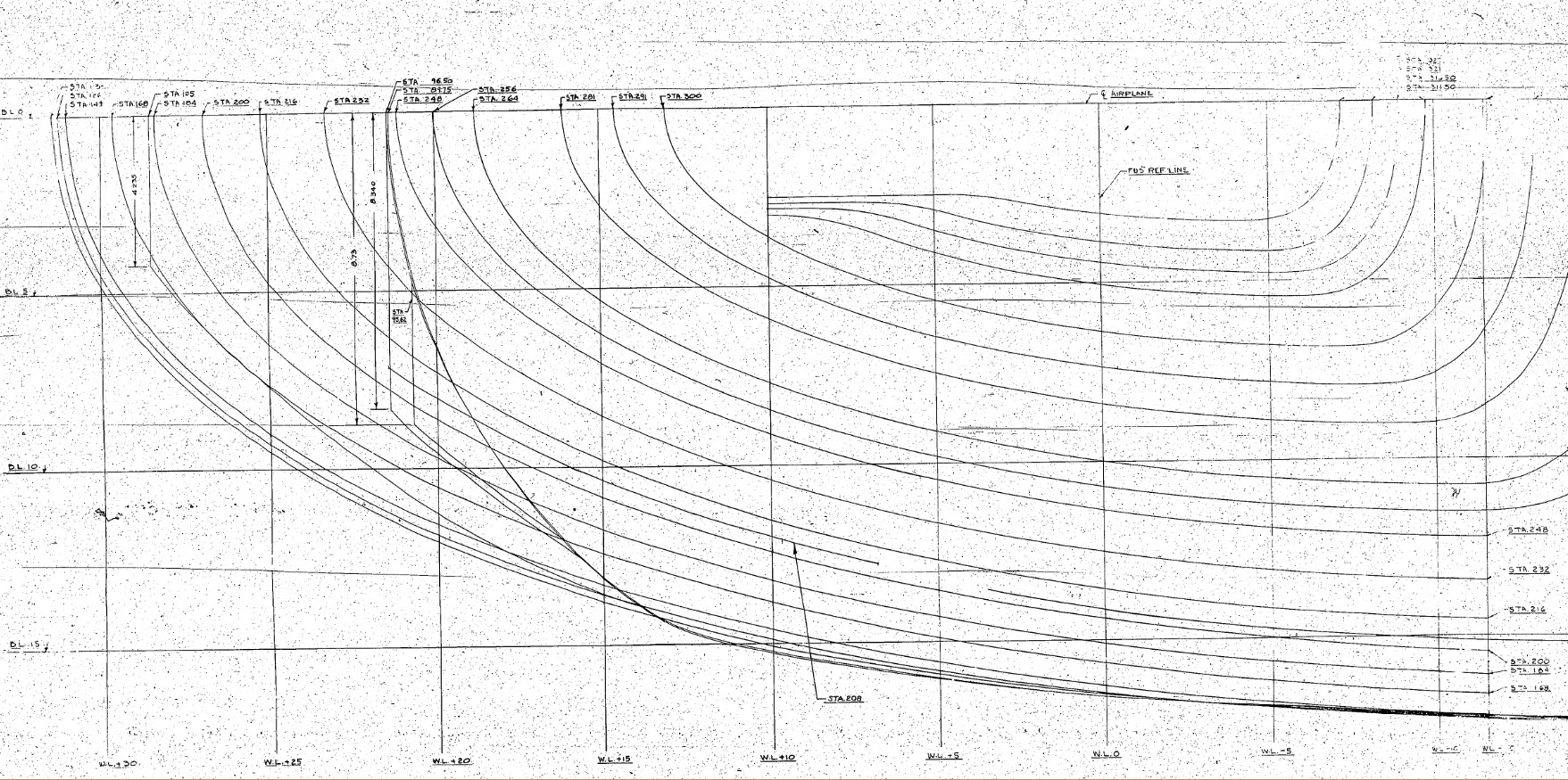
The image shown here is a screenshot from the NAA P-51 fuselage station profiles, which shows clearly the ideal curvature for each station.
This image can be overlayed in CAD to serve as an aid to achieve the correct spline curvature.
Actually manipulating the curvature of a spline needs to be done in a manner that achieves symmetrical results on both sides of the fuselage station profile.
I was working on the tail-end profiles, which were giving me grief as the ordinates points were not sufficient to achieve anything close to the curvature I needed on the lower section.
In Inventor we have constraints for symmetry, which are normally applied when working on a sketch to ensure that changes on one side of a model are reflected exactly in the other.
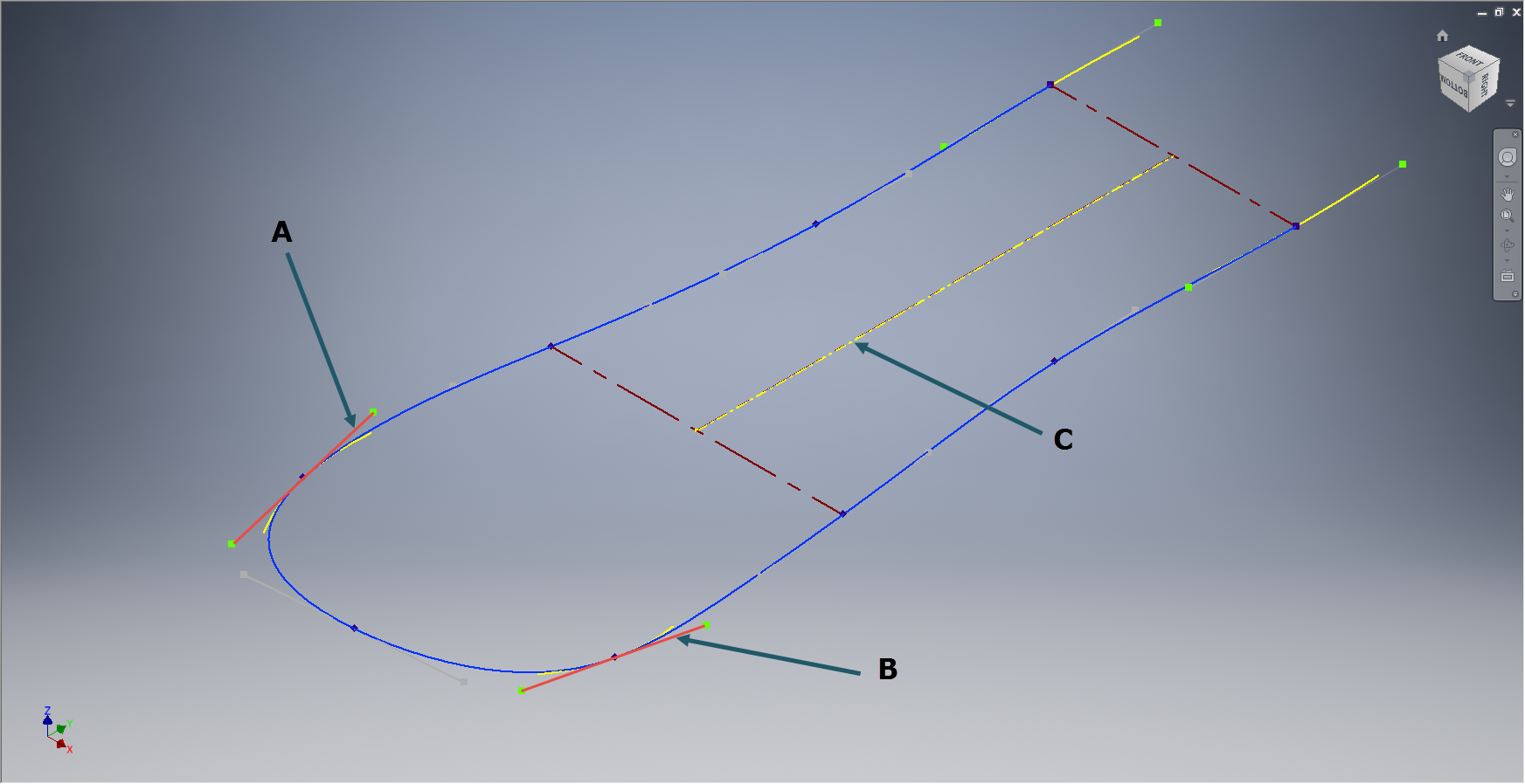
Using this same technique I activated the spline curvature handles (A&B) on each of the points I wanted to be symmetrical (about center at C) and applied the constraint accordingly to the handles (red).
 Now when I adjust one side of the curve the other side automatically reflects the changes.
I should note that the majority of curves generated from the ordinate points are usually very good; requiring very small if any adjustments; so its quite practical to spend some time in the areas where they are not so good.
At some stage the profiles will be lofted as a surface which would then be analysed to verify curvature and alignments.
