Fockewulf Ta152: Rudder Model:
The inclusion of many of the drawings for the rudder section with the scans I received prompted a new challenge for me. It is hard to resist the temptation to actually model this unit in its entirety, although potentially problematic due to the forming of the curved sheet metal elements.
This post has been updated as the previous day by day development process articles have been removed in a blog tidy up!


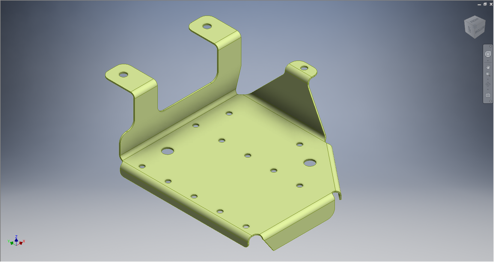
At this stage of the development I have the base structure in place along with four ribs and the components necessary to form the exterior profile. The individual models are fairly basic at this stage, still requiring a lot of detail work to complete them. My primary concern at this time is to check the relationships of each model in an assembly environment and also to derive the necessary interfaces to develop the next stage.


As I mentioned in my previous posts, the items are initially created from the manufacturing part drawings, which do not necessarily reflect actual ‘as-fitted’ state – so each component has to be developed to suit both criteria. The biggest problem I had with the ribs was with the lower unit that fits snugly between the triangular gussets. The forward part of this rib actually falls at a slope and has an angular bend line for the flanges which is dictated by the upward and outward slope of the gussets. In this instance I created a plane parallel to the inside face of the gussets in conjunction with construction geometry to mark the thickness deviation where the rib intersects with the inward profile of the vertical channel.
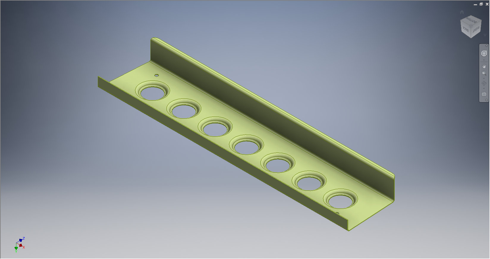
You may also have noticed the emboss feature in the ribs – which incidentally is a feature included as standard within Solidworks, my only gripe with this is that it only has one size listed – I will need to read up on the configuration options in Solidworks to create more size options. This also poses a dilemma – there are basically two types of embossing – the deformation of the surface as shown or similar but with a thru’ hole at the bottom – it is not clear on the drawings which is required and consequently I am having to make a best guess at what is required – so for now I will work with the emboss shown until my research can confirm otherwise.
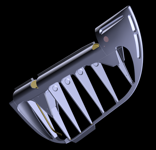
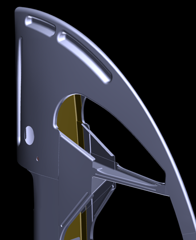
After many days of intensive work I eventually finished the model as shown below: