P-47 Ordinate Study Update
For most of this year, my primary focus has been the restoration project for the P-39 at Planes of Fame. That is still very much work in progress. At this stage, it is mainly the fabrication side of things, as the majority of controls have been drawn. The mounts for the Gunsight are currently being made. I hope to include some photographs of the installation in a later post.


The Gunsight was an extensive and challenging study…the drawing layout shown above was derived from a dozen or so blueprints and various manuals compiled together on one drawing. The circled dimensions are those verified from one or more sources.
During this time I have been doing some preliminary studies for the P-47. Over the last few weeks, the P-39 project demanded less of my time which has enabled me to further develop the ordinate study for the P-47.
The basic Layouts are developed for the Cowl, Fuselage, Empennage, Wings and Cockpit Enclosure. Still a lot of work to do on the details and resolve a number of queries.


One particular area of interest is the wings. As you can see a lot of work has been done on this layout which shows the Main Spars (shaded), Flaps and the leading and trailing edge profiles. The Aileron and Wing Tip is still a work in progress. The wing comprises 6 thickness variations of the S3 profile…15% at Sta 0 (Ctr aircraft), 14.2% at STA 74 (0.3 x Span), 12.3% at STA 123 (0.5 x Span), 10.5% at STA 172 (0.7 x Span), 9.2% at STA 222 (0.9 x Span) and 9.0% at Tip extent STA 246.
For the Main Spars we have the vertical dimensions coupled with the correct lines for the Flaps and Leading edge providing key important ordinate points that the rib airfoil profile should match. For the Airfoil ordinates I referenced documentation on the Republic S3 profile from the UIUC website and The NACA Technical Reports WRL-98 and WRL-159.
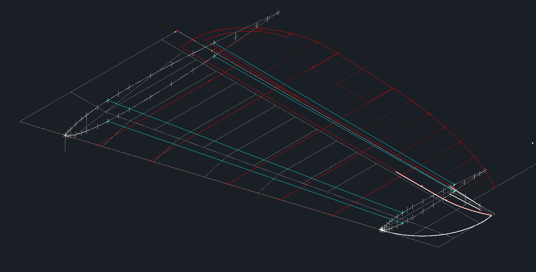
For The Horizontal Stabiliser we do have good information to develop a 2d plan layout including the dimensions for the Elevator to derive an accurate trailing edge. We lack sufficient depth information for any of the spars or ribs. Therefore, it is important to ensure we have the correct Stabiliser airfoil profiles.
The Republic blueprints list the airfoil ordinates at station 10.5 and station 83. These were recorded on spreadsheets and subsequently onto the CAD model. I found that the alignment for the spar positions and the 70% chord were slightly out. I reverse engineered the offset ordinate data to derive a Basic profile which I intend to use to further develop the intermediate ribs.

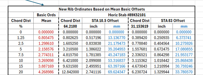
The first table above shows the recorded ordinate data for the airfoils at Sta 10.5 and 83. Working back from the offsets you can see the Basic Ordinates are similar but not exact. Therefore it seems logical to take the mean values from both tables to derive a workable basic profile which I can use later, shown in the middle column. The second table shows the adjusted ordinates for each profile. You may be asking what recognizable profile did Republic use for the stabilizer…again I do not know for sure. I have a parametric table setup for the more common NACA profiles used for other similar aircraft and none match.
The key dimensions for the profile relate to the 70% chord offset and the alignment with the front spar center. What I think is happening is the area from the leading edge to the 70% chord defines the surface for the Horizontal stabilizer and the curved trailing edge of the Elevator is essentially morphed to this line. What few vertical dimensions we have from several areas tend to match with this arrangement.
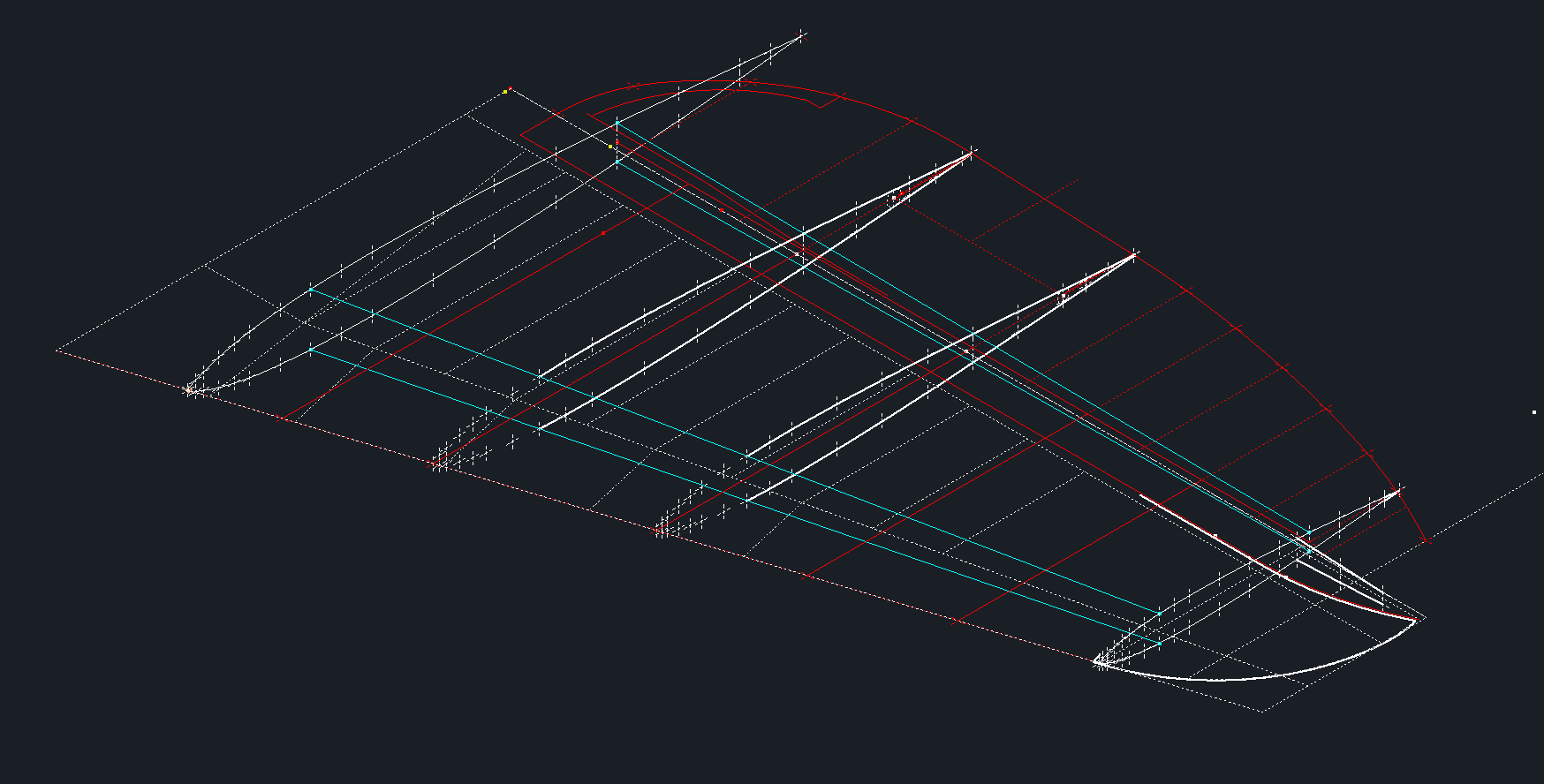
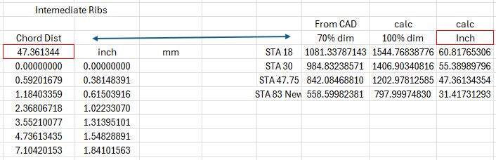
The cyan lines show the alignments at the front spar and the 70% chord for reference. The plan outline for the Elevator is drawn according to the known ordinate points. The second table above is designed to give me the airfoil offsets for any rib according to the chords derived from the CAD model…this is essentially the position of the measured 70% chord and is calculated to give me the actual chord length. All of this will be verified which means trawling through the many thousands of blueprints I have to find key offset data I can check against. Of course, I could use the Aircorps database for this but the many scans of this area are blacked out..the archive I have is much better quality.
I take nothing for granted with these studies and try to verify dimensional information from more than one source. I firmly believe that if we get the dimensional information correct everything else will fall into place.
As usual please get in touch with any technical queries or comments. hughtechnotes@gmail.com
Update 20th Dec 2024:
I have the basic geometry for the Horizontal Stabilizer and Elevator worked out…some detailed work is yet to be done on the Tip and the main Spars.

